

Page 1
-Do not store or use gasoline or other flammable vapors and liquids in the vicinity of this or any other
appliance.
-WHAT TO DO IF YOU SMELL GAS
Do not try to light any appliance.
Do not touch any electrical switch; do not use any phone in your building.
Leave the building immediately.
Immediately call your gas supplier from a neighbor’s phone. Follow the gas supplier’s
instructions.
If you cannot reach your gas supplier, call the fire department
-Installation and service must be performed by a qualified installer, service agency or the gas
supplier.
INSTALLER: Leave this manual with the appliance. CONSUMER: Retain this manual for future reference.
This appliance may be installed in an aftermarket, permanently located, manufactured home (USA only) or mobile home,
where not prohibited by local codes.
This appliance is only for use with the type of gas indicated on the rating plate. This appliance is not convertible for use
with other gases, unless a certified kit is used.
Installation Instructions
Model Numbers:
Numbers:
Single Side Units:
MQVL60N, MQVL60NE, MQVL60NE2, MQVL60LP, MQVL60LPE, MQVL60LPE2
Bay Peninsula Units:
MQVLBG60N, MQVLBG60NE, MQVLBG60NE2, MQVLBG60LP, MQVLBG60LPE, MQVLBG60LPE2
Certified to:
ANSI Z21.88-2017/CSA 2.33-2017 and CSA2.17-2017
VENTED GAS FIREPLACE HEATER
- Certified for use with Adjustable Vented Platform (AVP)
ENCLAVE
⚠ WARNING:
FIRE OR EXPLOSION HAZARD
Failure to follow safety warnings exactly could result in serious injury, death, or property damage.
A Division of R-Co. Inc. 2340 Logan Ave. Winnipeg, Manitoba Canada R2R 2V3 Ph.: (204) 632-1962
Printed in Canada April 27, 2020 Part# 60MQVL-MAN17
⚠ WARNING:
DO NOT OPERATE THIS APPLIANCE WITHOUT DECORATIVE
GLASS EMBERS ON BURNER AND MEDIA TRAY
VENTED GAS FIREPLACE HEATER:
NOT FOR USE WITH SOLID FUEL
Page 2
IT IS THE RESPONSIBILITY OF THE HOME OWNER TO ENSURE THAT NO ONE TOUCHES A HOT APPLIANCE.
If the barrier becomes damaged, the
barrier shall be replaced with the
manufacturer’s barrier for this
appliance.
Any safety screen, guard, or barrier
removed for servicing the appliance,
must be replaced prior to operating
the appliance.
Children and adults should be alerted
to the hazards of the high surface
temperatures of this appliance and
should stay away to avoid burns or
ignition of clothing.
Do not clean when the glass is hot.
Young children should be carefully
supervised when they are in the
same room as the appliance.
Toddlers, young children and others
may be susceptible to accidental contact burns.
A physical barrier is recommended if there are at risk individuals in the house. To restrict access to a fireplace or
stove, install an adjustable safety gate to keep toddlers, young children and other at risk individuals out of the room
and away from hot surfaces.
Do not leave the fireplace remote control where it is accessible to children.
WARNING:
A HORIZONTAL VENT CERTIFIED GUARD (SAFETY CAGE) IS AVAILABLE
WHEN REQUIRED BY LOCAL CODES.
SAFETY CAGES ARE AVAILABLE FOR ALL HORIZONTAL VENT TERMINATIONS.
CHECK WITH YOUR DEALER.
TERMINATION CAP IS HOT! Do not place flammable materials on or within 24 inches of termination caps.
It is imperative that the vent termination be located observing the minimum clearances as shown in manual.
There must not be any obstruction such as bushes, garden sheds, fences, decks or utility buildings within 24" from the
front of the termination plate.
Do not locate termination where excessive snow or ice build-up may occur. Be sure to check vent termination area after
snow falls and clear to prevent accidental blockage of venting system. When using snow blowers, make sure snow is not
directed towards vent termination area.
Venting terminal shall not be recessed into a wall or siding.
2
Page 3

Warnings, Installations and Operations - Installation Regulations
This gas appliance must be installed by a qualified installer in accordance with local building codes, or in the absence of local codes, with the
current CAN/CSA-B149.1 or .2 Installation Code (in Canada) or the current National Fuel Gas Code Z223.1- NFPA 54 when installed in the
United States.
This appliance, when installed, must be electrically connected and grounded in accordance with local codes, or in the absence of local codes,
with the current CSA C22.1 Canadian Electrical Code or with the National Electrical Code; ANSI/NFPA 70 when installed in the United States.
WARNING
FOR SAFE INSTALLATION AND OPERATION OF YOUR GAS FIREPLACE PLEASE NOTE THE FOLLOWING:
1. Do not clean when the glass is hot.
2. Do not use abrasive cleaners.
3. Using a substitute glass will void all product
warranties.
4. For safe operation, glass doors must be closed.
5. When purging the gas line, the glass front must be
removed.
6. Do not strike or abuse glass. Take care to avoid
breakage.
7. Do not alter gas orifice.
8. No substitute materials may be used other than
factory supplied components.
9. This appliance gives off high temperatures and should
be located out of heavy traffic areas and away from
furniture and draperies.
10. Children and adults should be alerted to the hazards
of the high surface temperatures of this appliance and
should stay away to avoid burns or ignition of clothing.
11. Young children should be carefully supervised when
they are in the same room as the appliance. Toddlers,
young children and others may be susceptible to
accidental contact burns. A physical barrier is
recommended if there are at risk individuals in the
house. To restrict access to a fireplace or stove, install
an adjustable safety gate to keep toddlers, young
children and other at risk individuals out of the room
and away from hot surfaces.
12. Under no circumstances should any solid fuels (wood,
paper) be used in this appliance.
13. Under no circumstances should this appliance be
modified. Any parts that have to be removed for
servicing should be replaced prior to operating this
appliance.
14. Any safety screen, guard, or barrier removed for
servicing an appliance must be replaced prior to
operating the appliance.
15. Installation and repair should be done by a qualified
service person. The appliance should be inspected
before use and at least annually by a professional
service person. More frequent cleaning may be
required due to excessive lint from carpeting, bedding
material, et cetera. It is imperative that control
compartments, burners and circulating air
passageways of the appliance be kept clean. Make
sure that the gas valve and pilot light are turned off
before you attempt to clean this unit.
16. Clothing or other flammable material should not be
placed on or near the appliance. This appliance
should not be used as a drying rack for clothing nor
should Christmas stockings or decorations be hung
from it.
17. Do not use this heater if any part has been under
water. Immediately call a qualified service technician
to inspect the heater and to replace any part of the
control system and any gas control which has been
under water.
18. Do not operate appliance unless completely installed
as per installation instructions.
19. Failure to position the parts in accordance with these
diagrams or failure to use only parts specifically
approved with this appliance may result in property
damage or personal injury.
20. WARNING: Do not operate appliance with the
glass front removed, cracked or broken.
Replacement of the glass should be done by a
licensed or qualified service person.
21. The appliance area must be kept clear and free from
combustible materials, gasoline, and other flammable
vapors and liquids.
22. The front of the fireplace gives off high temperatures
that could ignite combustible material which is kept
close to the front of the unit.
23. Ensure that power to the Fireplace is turned off before
servicing.
24. Do not operate this Fireplace without the glass front or
with a broken glass.
25. Improper installation, adjustment, alteration, service or
maintenance can cause injury or property damage.
Refer to the owner’s information manual provided with
this appliance. For assistance or additional information
consult a qualified installer, service agency, or the gas
supplier.
26. Operation of this appliance when not connected to a
properly installed and maintained venting system or
tampering with the blocked vent shutoff system can
result in carbon monoxide (CO) poisoning and
possible death.
27. This appliance is equipped with a three-prong
(grounding) plug for your protection against shock
hazard and should be plugged directly into a properly
grounded three-prong receptacle. Do not cut or
remove the grounding prong from this plug.
28. NOT INTENDED FOR USE AS A PRIMARY HEAT
SOURCE. This appliance is tested and approved as
either supplemental room heat or as a decorative
appliance. It should not be factored as primary heat in
residential heating calculations.
29. This appliance must not be connected to a chimney
flue serving a separate solid-fuel burning appliance.
3
Page 4

MQVL60 / MQVLBG60 Table of Contents
Cover......................................................................................................................................................................
1
Warnings.................................................................................................................................................................
2-3
Table of Contents....................................................................................................................................................
4-5
Installation Requirements for the Commonwealth of Massachusetts.....................................................................
6
Carbon Monoxide (CO) Detector............................................................................................................................
6
Pre-installation Questions and Answers.................................................................................................................
7
Operations and Maintenance Instructions..............................................................................................................
7
Mobile Home/Manufactured Housing Installation...................................................................................................
8
INSTALLATION & FRAMING
Framing Your Gas Fireplace...................................................................................................................................
9
Stand-off and Nailing Tab Locations.......................................................................................................................
9
Fireplace Installations in Covered Outdoor Locations............................................................................................
10
Vented Chase Requirements..................................................................................................................................
11
VL60AVP Adjustable Vented Platform....................................................................................................................
12-13
MQVL60 / MQVLBG60 Framing – Platform Base...................................................................................................
14
VL60EG Grill Installation.........................................................................................................................................
15
VL60EGS Side Grill................................................................................................................................................
16
Clearance to Combustibles.....................................................................................................................................
17
Mantel Clearances / Adjacent Wall.........................................................................................................................
18
MQVL60 Single Side
Locating Your Appliance.........................................................................................................................................
19
Fireplace Dimensions.............................................................................................................................................
19
Nailing Tab Guide...................................................................................................................................................
20
Single Side Framing................................................................................................................................................
21
Using Tile Lip..........................................................................................................................................................
22
Facing Requirements..............................................................................................................................................
22
VL60S1BL / VL60S1SS -Surround Installation for MQVL60...................................................................................
23-24
MQVL48SEP Side Extension Panels for MQVL60.................................................................................................
25
MQVL60 Glass Door Front Removal / Installation..................................................................................................
26
MQVLBG60 Bay Peninsula
Locating Your Appliance .......................................................................................................................................
27
Fireplace Dimensions.............................................................................................................................................
27
Bay Peninsula Framing...........................................................................................................................................
28
Bay Peninsula Nailing Tabs and Framing...............................................................................................................
29
VLBGCK Corner Kit for MQVLBGCK60..................................................................................................................
30-32
Using Tile Lip..........................................................................................................................................................
33
Facing Requirements..............................................................................................................................................
33
General Installation, Use, And Maintenance
MQVLBG60 Front Glass Installation and Removal................................................................................................
34
MQVLBG60 – Side Glass Door Removal and Installation......................................................................................
35
Door and Glass Information....................................................................................................................................
36
MQVL60 / MQVLBG60 Glass Safety Barrier Installation / Removal.......................................................................
37
Component Locations.............................................................................................................................................
38
LED Lighting...........................................................................................................................................................
39
Accessories and Options
VL60PLB Porcelain Back Liner Installation.............................................................................................................
40
VL48PLE Porcelain End Liner Installation..............................................................................................................
41
MQVL60RGB Glass Back Liner Installation............................................................................................................
42
MQVL48RGE Glass End Panel Installation............................................................................................................
43-44
MQVL60RLSB / MQVL48RLSE Stacked Brick - MQVL60RLFB / MQVL48RLFE Fluted Liner Installation............
45-46
MQ Dealer Accessories..........................................................................................................................................
47
MQ46D Driftwood Log............................................................................................................................................
47
4
Page 5

MQROCK2, MQROCK3, MQRBD1........................................................................................................................
48
MQ STONE Decorative Stone Set..........................................................................................................................
48
MQEMBER.............................................................................................................................................................
48
MQRBD3 - 5 Piece Driftwood Log Set....................................................................................................................
49
MQLOGF48D - 6 Piece Driftwood Log Set.............................................................................................................
50
MQRBBW – 5 Piece Birchwood Log Set................................................................................................................
50
Burner System
Gas Line Installation / Gas Specifications Chart....................................................................................................
51
Millivolt System, Lighting, and Burner Control........................................................................................................
52
Troubleshooting the Gas Control System...............................................................................................................
53
Annual Inspection List for Determining Safe Operation of a Direct Vent Gas Fireplace........................................
54
Burner System Maintenance...................................................................................................................................
55
Gas Conversion Part A...........................................................................................................................................
56
Gas Conversion for Top Convertible Pilot – Part B.................................................................................................
57
Gas Conversion for Modulator – Part C..................................................................................................................
58
False Bottom Removal / Burner Tube Removal.....................................................................................................
59
Burner System Removal and Installation................................................................................................................
59
Proflame 1
Overview / Components..........................................................................................................................................
60
Remote Control Operation......................................................................................................................................
61
Proflame 1 Parts List..............................................................................................................................................
62
Configuration #2: Remote ON/OFF and Manual HI/LO Capabilities......................................................................
63
Configuration #3: Remote ON/OFF, variable HI/LO, and Fan Capabilities.............................................................
64
Operating the Receiver Without Batteries- Millivolt and Proflame 1.................................................................................
65
Electronic Ignition Lighting Instructions...................................................................................................................
66
Proflame 2
Proflame 2 Parts List...............................................................................................................................................
67
Proflame 2 Module and Remote Control.................................................................................................................
68
Cold Climates – CPI Setting - Proflame 2 Remote Control.....................................................................................
69
Proflame 2 Remote Control Operation....................................................................................................................
70-71
Proflame 2 Label Diagram................................................................................................................................................
72
Venting
Vent Terminal Clearances......................................................................................................................................
73
General Vent Installation…………………………………………………………………………………………………...
74
Installation of Side Wall Venting…………………………………………………………………………………………...
74
Venting Routes And Components…………………………………………………………………………………………
75
Horizontal Venting Table…………………………………………………………………………………………………...
75
Venting Straight Up Through Roof………………………………………………………………………………………...
76-77
Approved for Power Vent PVH58 / PVH58FM........................................................................................................
78
Parts Lists
PVH58 / PVH58FM Parts List.................................................................................................................................
79
Fireplace Models.....................................................................................................................................................
80
MQVL60 / MQVLBG60 Parts List...........................................................................................................................
81-82
Warranty
Limited Lifetime Warranty………………………………………………………………………………………………......
83
5
Page 6
Installation Requirements for the Commonwealth of Massachusetts
In the Commonwealth of Massachusetts, the installer or service agent shall be a plumber or gas fitter licensed by the
Carbon Monoxide (CO) Detector
NOTE: It is recommended that a Carbon Monoxide (CO) Detector be installed in or near bedrooms and on all levels of
your home. Place a detector about 15ft [4.5m] outside the room that houses your gas appliance.
Certified for installation in a bedroom or bed/sitting room. In Canada must be installed with listed millivolt thermostat.
In USA see local codes.
6
Commonwealth.
When installed in the Commonwealth of Massachusetts or where applicable codes; the unit shall be installed with a CO
detector per the requirements listed below.
1. For direct-vent appliances, mechanical-vent heating appliances or domestic hot water equipment, where the bottom of
the vent terminal and the air intake is installed below four feet above grade the following requirements must be
satisfied:
A. If there is not one already present, on each floor level where there are bedroom(s), a carbon monoxide
detector and alarm shall be placed in the living area outside the bedroom(s). The carbon monoxide detector
shall comply with NFPA 720.
B. A carbon monoxide detector shall be located in the room that houses the appliance or equipment and shall:
Be powered by the same electrical circuit as the appliance or equipment such that only one service switch
services both the appliance and the carbon monoxide detector;
Have battery back-up power;
Meet ANSI./UL 2034 Standards and comply with NFPA 720; and
Have been approved and listed by a Nationally Recognized Testing Laboratory as recognized under 527
CMR.
C. A Product-approved vent terminal must be used, and if applicable, a Product-approved air intake must be
used. Installation shall be in strict compliance with the manufacturer’s instructions. A copy of the installation
instructions shall remain with the appliance or equipment at the completion of the installation.
D. A metal or plastic identification plate shall be mounted at the exterior of the building, four feet directly above
the location of vent terminal. The plate shall be of sufficient size to be easily read from a distance of eight feet
away, and read “Gas Vent Directly Below”.
2. For direct-vent appliances, mechanical-vent heating appliances or domestic hot water equipment where the bottom of
the vent terminal and the air intake is installed above four feet above grade the following requirements must be
satisfied:
A. If there is not one already present, on each floor level where there are bedroom(s), a carbon monoxide
detector and alarm shall be placed in the living area outside the bedroom(s). The carbon monoxide detector
shall comply with NFPA 720.
B. A carbon monoxide detector shall:
Be located in the room that houses the appliance or equipment;
Be either hard-wired or battery powered or both; and
Shall comply with NFPA 720.
A Product-approved vent terminal must be used, and if applicable, a Product-approved air intake must be used.
Installation shall be in strict compliance with the manufacturer instructions. A copy of the installation instructions shall
remain with the appliance or equipment at the completion of the installation.
For the state of Massachusetts a T-handle gas shut-off valve must be used on a gas appliance. This T-handle gas shutoff valve must be listed and approved by the state of Massachusetts. This is in reference to the state of Massachusetts
state code CMR238.
Page 7

Pre-installation Questions and Answers
Operations and Maintenance Instructions
Be sure to read and understand all the instructions in this manual before operation of appliance.
Ensure all wiring is correct and properly enclosed to prevent possible shock.
Check for gas leaks.
Make sure the glass door is properly installed before operation. Never operate the appliance with the glass door
removed.
Make sure venting and termination cap are installed and unobstructed.
If brick or porcelain liners are used, ensure they are installed.
Verify that the pilot can be seen when lighting the appliance. If not, the log or rock placement is incorrect.
If the unit is turned off, you must wait a minimum of 60 seconds before re-lighting it.
Venting systems should be periodically examined by a qualified agency.
The flow of combustion and ventilation air must not be obstructed.
The Burner/Log Assembly has been engineered and permanently adjusted for proper flame control.
Periodically remove the logs from the grate assembly and vacuum any loose particles from the grate and burner
areas. See Log Placement page to remove logs. Vacuum burner parts and replace logs.
Never use your gas fireplace as a cooking device.
Label all wires prior to disconnection when servicing controls. Wiring errors can cause improper and dangerous
operation. Verify proper operation after servicing.
Areas in and around the Chase Vent Openings should be cleaned annually.
7
About curing of the paint
Your stove or fireplace has been painted with the highest quality silicone stove paint. This paint dries quickly in 15-20
minutes when first applied at the factory. However, due to the high temperature silicone components, the paint will cure
when heat is applied to the appliance as it is first used. The following information applies to the curing process to get the
paint fully hard and durable.
Fire the appliance four successive times for 10 minutes each firing and a 5 minute cool down between each. Be aware
during log and firebox paint curing that a white deposit may be developing on the inside of the glass doors. It is important
to remove this white deposit from the glass doors using a fireplace glass cleaner.
Babies, small children, pregnant women and pets should leave the area during the cure phase.
Ventilate well, open doors and windows.
Do not touch during curing.
Why does my fireplace or stove give off odor?
It is normal for your fireplace to give off some odor at first. This is due to the curing of the paint, adhesives, silicones and
any undetected oil from the manufacturing process as well as the finishing materials used with the installations (e.g.
marble, tile and the adhesives used to adhere this product to the walls can react with heat and cause odors).
It is recommended that you burn your gas fireplace or stove for a minimum of four hours at a time with the fan off (if a fan
is present) after the curing of the paint has been completed. These odors can last upward to 40 hours of burn time; keep
burning at a minimum of four hours per use until odors dissipate.
Noise coming from the fireplace?
Noise is caused by the expansion and contraction of metal as the appliance heats up and cools down. This is normal and
is similar to the sounds produced by a furnace or heating duct. This noise does not affect the operation or longevity of
your fireplace.
It is also normal for the fan to make some noise when it comes on. This noise can be reduced somewhat by turning down
the speed of the fan with the variable speed control. Be aware, however, that this will reduce the volume of heated air
circulated into the room by the fan.
Note to the Installer:
Be sure appliance is working properly and its operation (including remote control operation, if included) is fully explained
to and understood by the customer.
For safe installation and operation note the following:
Page 8
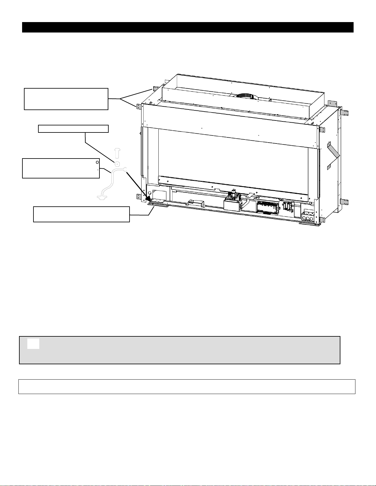
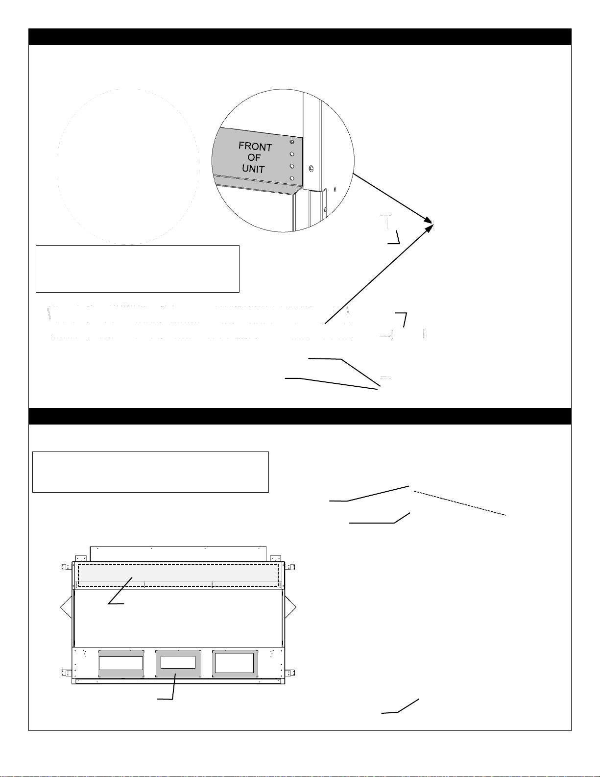
Mobile Home/Manufactured Housing Installation
Warning: Do not compromise the structural integrity of the manufactured home wall, floor
or ceiling, during installation of appliance or venting.
Appliance Must Be Secured To
Structure Using Supplied Nailing
Tabs And Or Fastened To Floor.
Use Existing Hole Or Remove Existing
Screw To Mount Ground Wire.
Serrated or Star Washer
Ground Wire from Appliance to
Steel Chassis of Mobile Home.
USE 8GA COPPER WIRE.
8
This Direct Vent System Appliance must be installed in accordance with the manufacturer’s installation instructions and the
Manufactured Home Construction and Safety Standard Title 24 CFR, Part 3280, or the current Standard for Fire Safety Criteria for
Manufactured Home Installations, Sites, and Communities ANSI/NFPA 501A, and with CAN/CSA Z240 MH Mobile Home Standard in
Canada.
THE VENTED GAS FIREPLACE HEATERS (ANSI Z21.88) IN THIS MANUAL MAY BE INSTALLED IN MANUFACTURED (MOBILE)
HOMES AFTER FIRST SALE IN THE USA.
THE VENTED GAS FIREPLACE HEATERS (ANSI Z21.88) IN THIS MANUAL MAY BE INSTALLED IN MANUFACTURED (MOBILE)
HOMES IN CANADA.
Please follow the current ANSI/NFPA 70 National Electrical Code in the USA and CAN/CSA C22.1 Canadian National
Electrical Code in Canada.
An appliance must be grounded to the steel chassis of the home with 8 ga. copper wire using a serrated or star washer to
penetrate paint or protective coating to insure grounding.
Use carriage bolt at the attachment point (see diagram above) to secure the appliance to the floor.
For required venting components see venting installation in appropriate section of this manual.
Certified for installation in a bedroom or bed/sitting room. In Canada must be installed with listed millivolt thermostat. In USA see local
codes.
Page 9
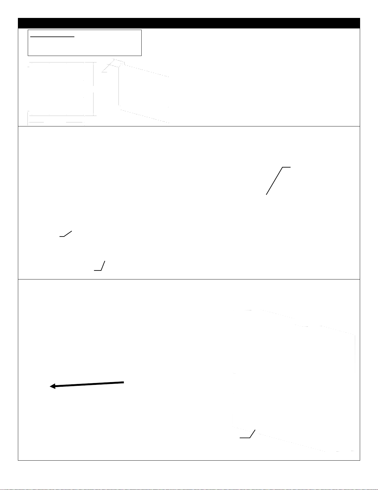
Fireplace Installations in Covered Outdoor Locations
– FOR BASIC MILLIVOLT UNITS ONLY- NO FAN – NO LIGHTS-
Kingsman and Marquis Direct Vent fireplaces may be installed into outdoor locations provided they are suitably protected
CAUTION – Installation of an indoor gas fireplace with an outdoor exposure is not covered under the (ANSI
Z21.88 – CSA 2.22 or ANSI Z21.50 – CSA 2.33) standard(s) used to certify the indoor gas-fired fireplace. The
Intertek safety certification will not apply to this installation method. This installation method must be deemed
acceptable by the Authority Having Jurisdiction (AHJ) prior to the indoor gas fireplace being installed.
OUTDOOR
AREA
Glass
Glass
Door
Glass
Outside Wall
of House
9
from direct water impingement. However, all installation clearances in the appliance manual must be observed. Framing,
Clearances to Combustibles, Mantel Heights, Facing Requirements, Venting Installation, etc. Use supplied Safety Screen.
All wiring connections to line power shall be in accordance with outdoor requirements of; -NECA NFPA 70 in the USA
-Canadian Electrical Code, CSA C22.1 for Canada.
The Fireplace is not to be operated in temperatures below freezing (0°C / 32°F).
⚠ NOTE: TEMPERED GLASS WARNING: Tempered glass is vulnerable to rapid and/or extreme changes in
temperature (thermal shock). Take care to prevent water from contacting the fireplace, especially if it is hot.
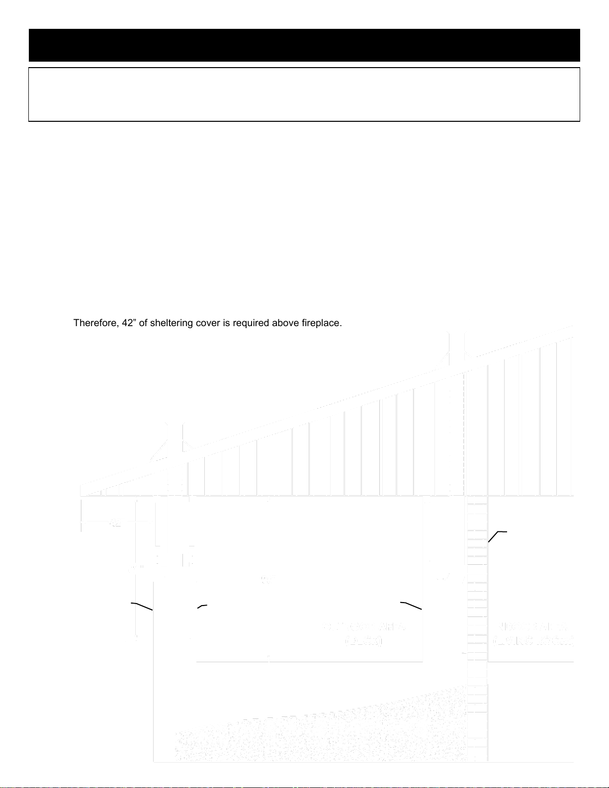
See-Through Units are suitable for an outdoor location, but not on the outside wall of a house or other structure, as
air flows through both sides of the fireplace.
A Minimum sheltering cover (overhang) of 1/2 the distance from the base of the fireplace to the ceiling (base of
roofline) is required.
EXAMPLE: The bottom of the fireplace is 84” from the ceiling.
Therefore, 42” of sheltering cover is required above fireplace.
Page 10
MQVL60 / MQVLBG60 Framing Your Gas Fireplace
This section is intended for qualified installers only. Before beginning, make note of where the gas and electrical accesses
Specifications
1. Cold climate installation recommendation: When installing this fireplace against non-insulated exterior wall or chase, it
is recommended that the outer walls be insulated to conform to applicable insulation codes. Drywall & vapor barrier
must be installed over insulation to prevent contact of insulation and unit.
2. Choose fireplace location and frame in accordance with the fireplace framing dimensions specified (view diagrams).
3. Drywall or other combustible material can extend up to the Drywall Stops located on the sides of the unit, and up to
the bottom and top.
4. A Hearth is not required for this unit.
Certified for installation in a bedroom or bedsitting room. In Canada must be installed with listed millivolt thermostat (Not
permitted for decorative vented gas fireplaces installed in the U.S.A.). In USA see local codes.
Stand-off and Nailing Tab Locations
Make note of where the stand-off locations are. These stand-offs are provided as indicators to illustrate the boundaries
for framing. Therefore, no framing material is permitted to extend beyond these stand-offs.
Vertical Venting in Cold Climates
In cold climate conditions where temperatures go below -10 degrees Celsius or 14 degrees Fahrenheit, we recommend
that the chase be insulated and where the vent pipe enters into the attic space that the pipe be wrapped with an
insulated Mylar sleeve. This will increase the temperature of the vent and help the appliance to vent properly in cold
weather conditions.
It is also important in vertical vented direct vent appliances that the appliance be operated daily during the winter months
as this will help stop the termination from freezing up. We recommend using a thermostat (Not permitted for decorative
vented gas fireplaces installed in the U.S.A.) set at room temperature to allow the unit to cycle.
For IPI models it may be necessary to set the appliance to Standing Pilot mode to maintain heat in the cavity. The
purpose of this procedure is to prevent cold air from penetrating the chimney and then onto the living space. Therefore,
when the internal temperature is slightly elevated the fireplace is able to freely exhaust its combustion and hence making
it easier to startup.
Holes are provided in bottom of unit to
secure appliance to floor after installation.
Rotating
Nailing Tab
Nailing Tab- Lift
up to attach to
framing above unit.
Stand-off – 3/8” Tall
Stand-off- Raise
into position and
fasten with DT
Screw provided.
Rotating
Nailing Tab
Stand-off – 3/8” Tall
Stand-off- Raise
into position and
fasten with DT
Screw provided.
10
are located on the unit. This will streamline the construction process. Furthermore, familiarize yourself with the venting
and clearance requirements (see Venting section) for this appliance. Failure to comply with those requirements can
seriously compromise the safety and operation of the fireplace.
Page 11
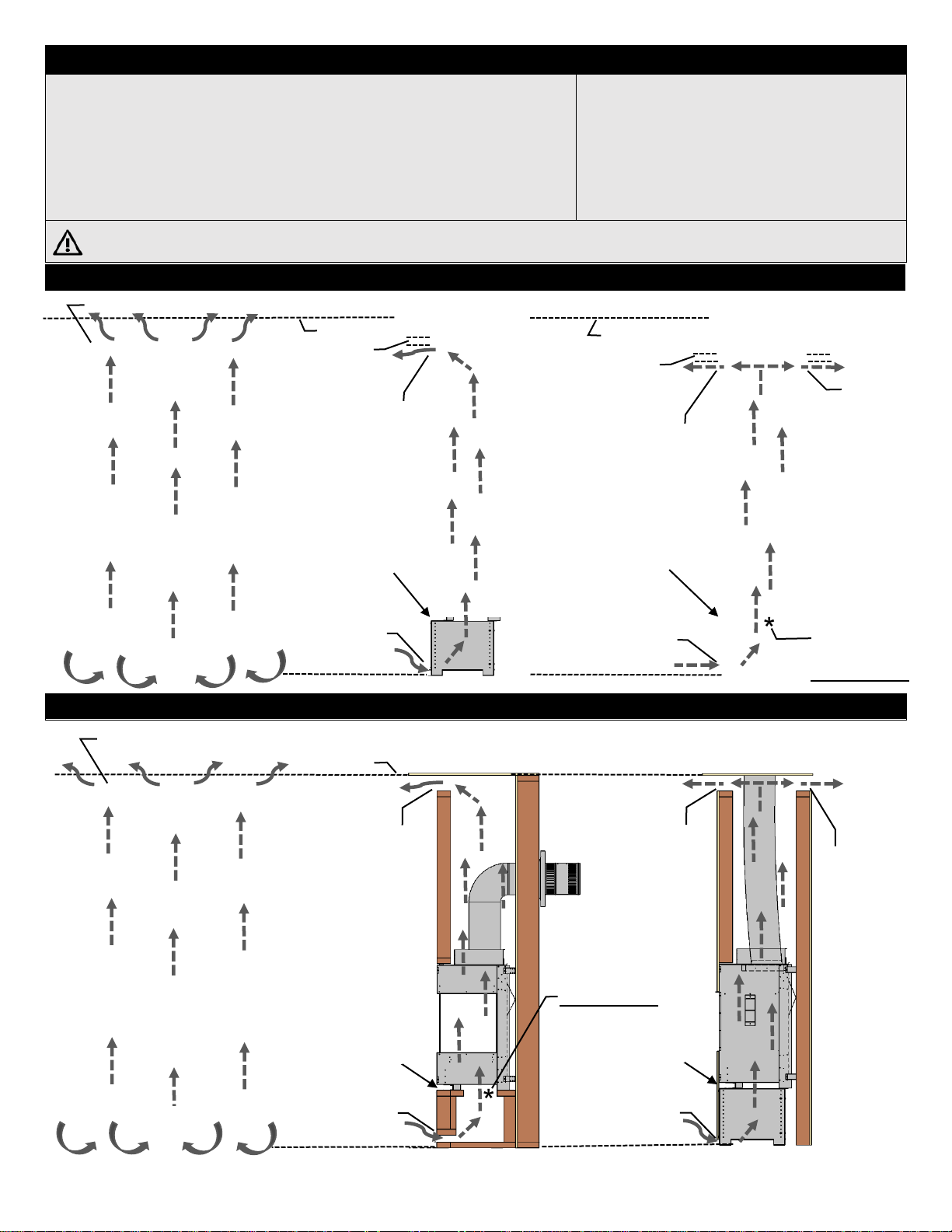
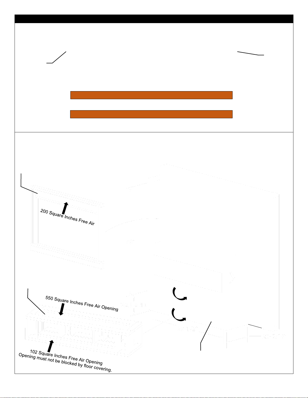
MQVL60 / MQVLBG60 VENTED CHASE REQUIREMENTS
FIREPLACE CHASE MUST BE VENTED AT TOP AND BOTTOM- Minimum
200 square inches free air opening at the top of the chase, and minimum 102
square inches free air opening at the bottom of the chase.
Platform must have minimum 550 Square inches free air opening.
Chase Vent Openings LARGER than the required minimums ARE allowed and
will reduce surface temperatures.
HEAT CANNOT BE DISCHARGED INTO THE WALLS, FLOOR, OR CEILING.
Heat must exit through the required vented chase opening near the ceiling.
ELECTRICAL WIRES IN CHASE MUST BE
PROPERLY ATTACHED TO INSIDE WALL OF
CHASE. DO NOT RUN WIRES ABOVE
APPLIANCE.
Please follow the current CSA C22.1 Canadian
Electrical Code or the National Electrical Code;
ANSI/NFPA 70 when installed in the United
States.
If using insulation in vented chase (i.e. for outside wall), wall board / drywall is required to support all insulation.
Vented chase must be clean and free of all debris (i.e. loose insulation, pieces of wood, etc.)
-Framing for Vented Chase with Grills-
MQVL60 / MQVLBG60 -Framing for Vented Chase with Openings - No Grills-
102 Sq. In.
Air Option
Fireplace Support must be
open to allow air to flow
through fireplace.
Uses Kingsman
VL60EG Front Grill,
VL60EGS Side Grills,
Or Grill with
Minimum 220 Sq. In.
Free Air Equivalent
Required
Minimum 102
Sq. In. Free Air
Fireplace Support must be
open to allow air to flow
through fireplace.
Ceiling
Ceiling
102 Sq. In.
Air Option
Optional – Secondary
Vent can be added
Required
Minimum 102
Sq. In. Free Air
Required
Minimum 102
Sq. In. Free Air
102 Sq. In.
Air Option
Required
Minimum 200
Sq. In. Free
Air in Sides or
Front
102 Sq. In.
Air Option
Required
Minimum102
Sq. In. Free Air
This area must
be open MIN 550 Sq. In.
Grill with
Min 220 Sq. In.
Must be in the
same Pressure
Zone
(Room / Area)
This area must
be open MIN 550 Sq. In.
Ceiling
Flush or 3/4”
MAX from top
of Chase
Optional Adjustable Vented Platform (VL60AVP)
Optional – Secondary
Vent can be added
Min 200 Sq. In.
Must be in the
same Pressure
Zone
(Room / Area)
Can be vented at Side, Front, or Rear. MIN 220 Sq. In. Grill
Required
Minimum 200
Sq. In. Free
Air in Sides or
Front
Can be vented at Side, Front, or Rear. MIN 200 Sq. In. Opening
Example: 51” x 2”
Flush or 3/4”
MAX from top
of Chase
Uses Kingsman
VL60EG Front Grill,
VL60EGS Side Grills,
Or Grill with
Minimum 220 Sq. In.
Free Air Equivalent
Example: 51” x 2”
Top Opening must be 60-5/8” wide, 3-5/8” tall, and within 3/4” of Enclosure Top.
Top Opening must be 60-5/8” wide, 3-5/8” tall, and within 3/4” of Enclosure Top.
11
Page 12
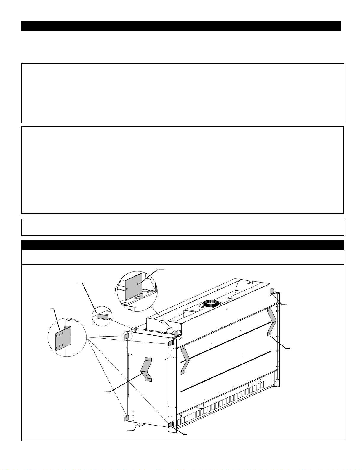
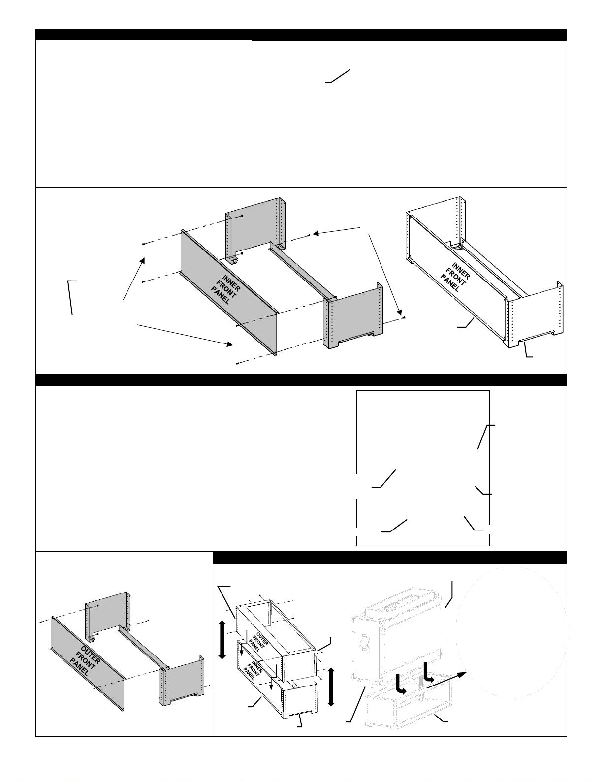
Adjustable Vented Platform VL48AVP, VL60AVP, VL72AVP -Option
The Adjustable Vented Platform is an
optional installation base. Height is
variable from approximately 14-3/4” to
27-1/4”.
The Front
Opening of
the Adjustable
Vented
Platform
meets the
required
minimum
opening.
The Side Openings have 20 or 27 square inches of
opening each (depending upon the setting). They can be
closed in if the required minimum opening has already
been achieved (i.e., the front opening of the AVP is used).
The Tile Lip on the Side of the Platform is detachable.
ADJUSTABLE VENTED PLATFORM PARTS LIST
ITEM
NO.
DESCRIPTION
QTY.
1
Inner Side Panel
2 2 Outer Front Panel
1
3
Rear Brace
2 4 Outer Side Panel
2
5
Inner Front Panel
1 6 #8 x 5/8” Low Profile Screw
37 7 1/4-20 x 1/2” Self-Clinching Stud
4 8 1/4-20 Nut with Serrated Washer
4
9
Side Tile Lip
2
20 or 27
Sq. In
Opening on
each side
Meets Bottom Opening
Requirement*
*Front Openings
Dimensions
Area
VL48AVP
1-3/4” x 52-1/2”
91-7/8” Sq. In.
VL60AVP
1-3/4” x 64-1/2”
112-7/8” Sq. In.
VL72AVP
2-1/8” x 76-1/2”
162-1/2” Sq. In.
Side Tile
Lip is
Detachable
CONTINUED ON NEXT PAGE
Top
Base
INNER
SIDE
PANEL
INNER
SIDE
PANEL
OUTER
SIDE
PANEL
OUTER
SIDE
PANEL
UNEXTENDED BASE
FULLY EXTENDED BASE
IMPORTANT NOTES:
AVP SHOULD BE IN PLACE BEFORE UNIT IS INSTALLED.
ATTACH FIREPLACE TO AVP WITH SCREWS PROVIDED.
FIREPLACE SHOULD BE NOT BE MOVED ONCE INSTALLED ON AVP.
FIREPLACE MUST BE SECURED TO FRAMING ONCE INSTALLED ON AVP.
12
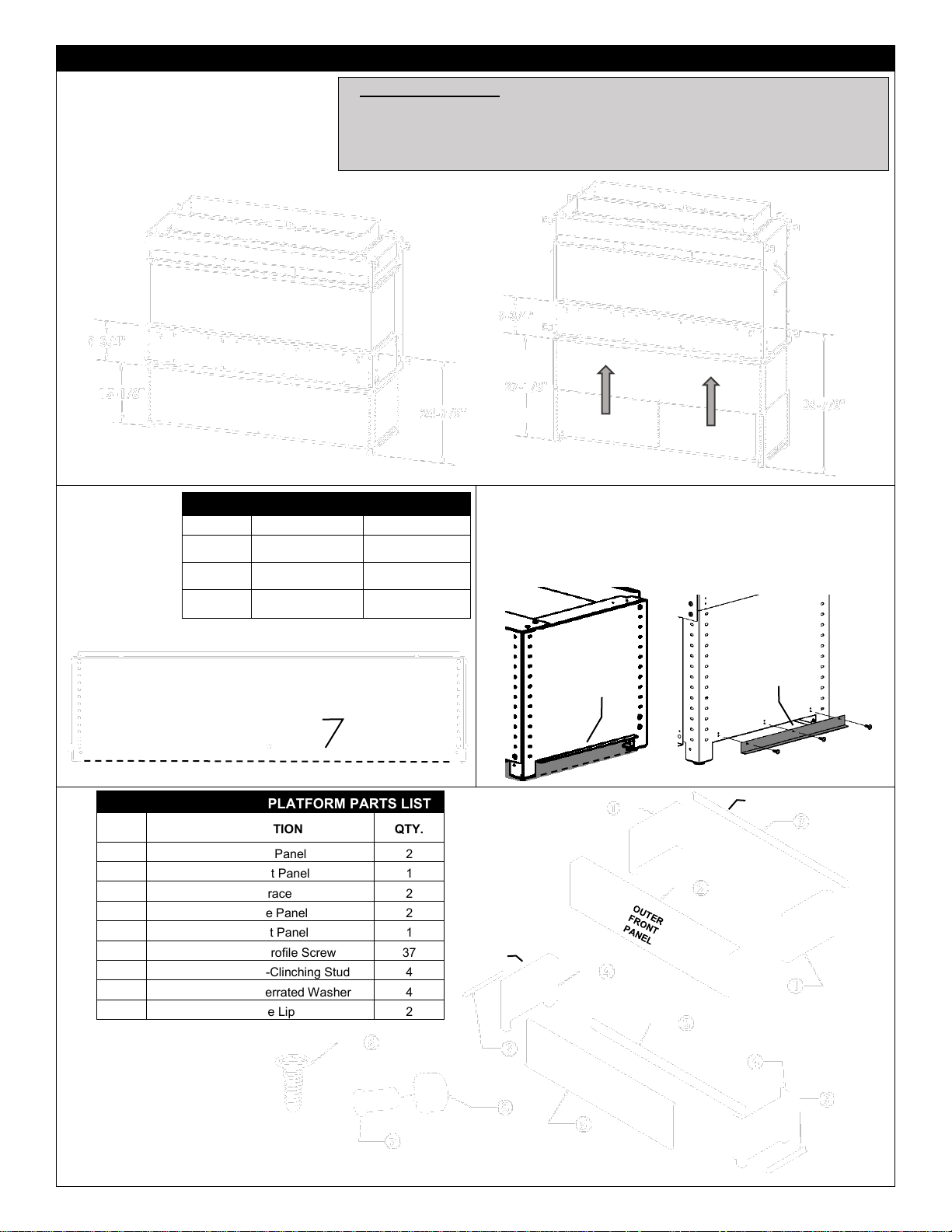
Page 13
STEP ONE: ASSEMBLE BASE
STEP TWO: ASSEMBLE TOP
STEP THREE: ASSEMBLE PLATFORM AND SET AT DESIRED HEIGHT
REAR BRACE
OUTER
SIDE
PANEL
OUTER
SIDE
PANEL
INNER
FRONT
PANEL
SELF-
CLINCHING
STUD
1. Assemble Base of Platform
using supplied self-clinching
studs, nuts, and screws.
X4
SELFCLINCHING
STUD
X2
OUTER
SIDE
PANEL
OUTER
SIDE
PANEL
TILE LIP
TILE LIP
INNER
SIDE
PANEL
INNER
SIDE
PANEL
REAR BRACE
OUTER
FRONT
PANEL
OUTER
FRONT
PANEL
TILE LIP
TILE LIP
OUTER SIDE
PANEL
INNER SIDE
PANEL
2. Assemble Top using
supplied screws.
INNER
SIDE
PANEL
INNER
SIDE
PANEL
OUTER FRONT
PANEL GOES TO
OUTSIDE
INNER SIDE
PANEL
OUTER
SIDE
PANEL
INNER SIDE
PANEL
GOES TO
INSIDE
TILE LIP
TILE LIP
HOOK BACK OF FIREPLACE INTO BACK OF
PLATFORM AND ATTACH FRONT WITH SCREWS.
ATTACH FIREPLACE TO
PLATFORM AND TO FRAMING.
OUTER
SIDE
PANEL
OUTER
SIDE
PANEL
ATTACH
WITH
SCREWS
13
Page 14
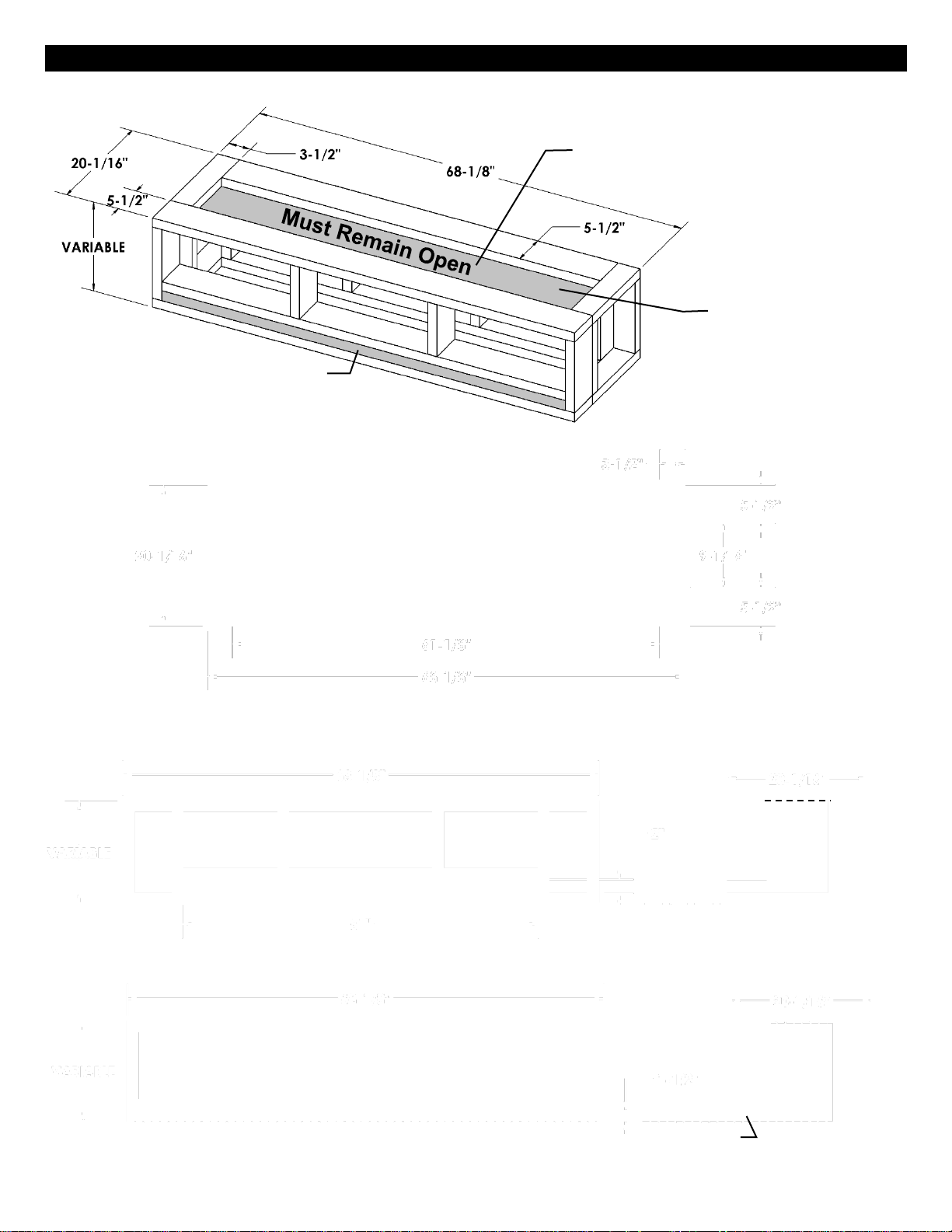
MQVL60 / MQVLBG60 Framing – Platform Base
A Platform Base has air opening requirements that must be met.
Example Only: Front or Side Must
Square
Free Air Opening
Example: 51” x 2”
Top of Platform Must Have
Minimum 550 Square
Inches Free Air Opening
⚠ DO NOT COVER
TOP OF
PLATFORM.
550 Square Inches
Free Air Opening
TOP VIEW
EXAMPLE 1: FRONT VIEW
SIDE VIEW
550 Sq. In.
SIDE VIEW
550 Sq. In.
EXAMPLE: 2” X 51” = 102 Square Inches
EXAMPLE: 1-1/2” X 68” = 102 Square Inches
EXAMPLE 2: FRONT VIEW
Opening must not be blocked
by floor covering.
Must Remain
Open
14
Have Minimum 102
Inches
Page 15

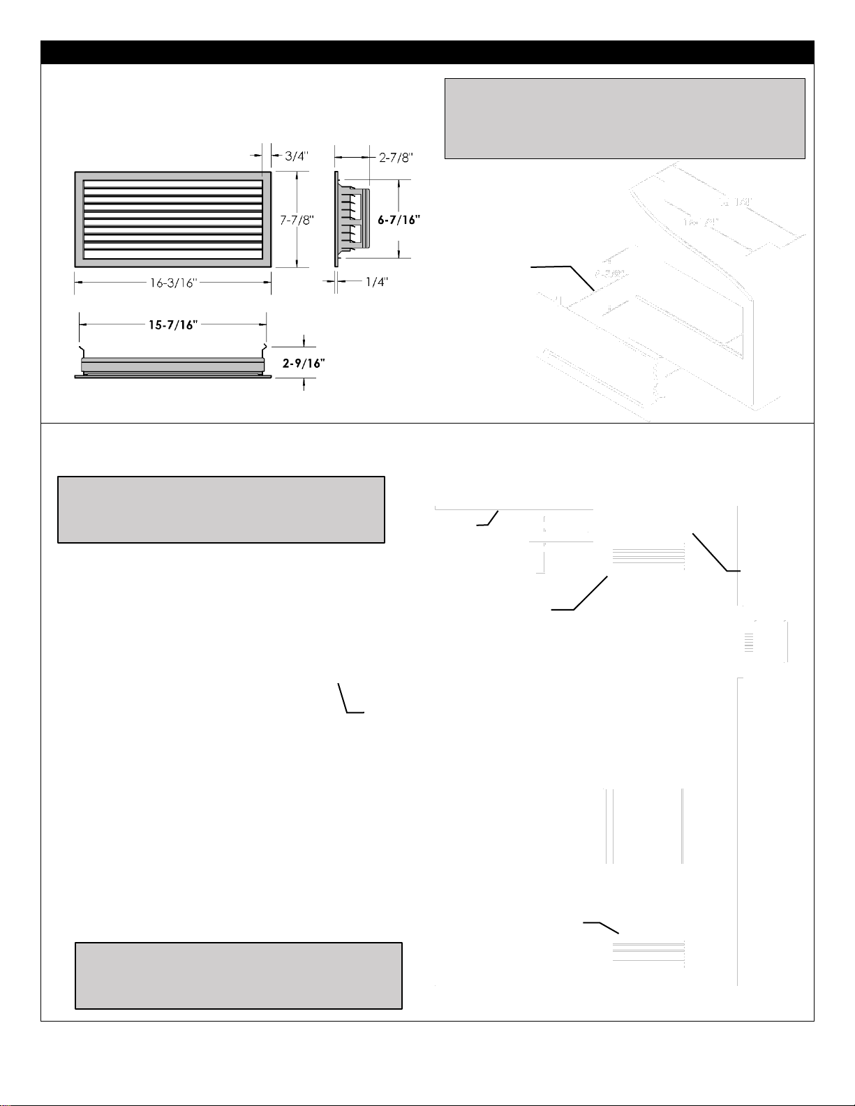
VL60EG Grill Installation- Compatible with Vented Chase -Option-
Parts List:
[1] Louver Grill (ready to paint)
[1] Outer Trim Grill Mount (ready to paint)
[1] Upper Frame for Hidden Grill Mount
[1] Lower Frame for Hidden Grill Mount
[8] #6 Black Screws
This Kit comes with two installation options:
Outer Trim Grill Mount - For a Quick and simple installation.
Hidden Grill Mount - For a very clean installation with only the grill
visible in the finished opening.
⚠ Grill openings must be flush with or within 3/4” of enclosure top.
This is to prevent excess heat from becoming trapped in the top of
the chase. See installation section of manual.
USING OUTER TRIM MOUNT: -Required Opening Dimension is 60-5/8” wide x 3-5/8” tall x 2” deep.
Insert Trim into opening and fasten to framing with a wood screw at each end.
-Then insert Grill and attach with supplied #6 black screws. Do not over tighten screws.
USING HIDDEN GRILL MOUNT:
-Required Opening Dimension is
60-5/8” wide x 3-5/8” tall x 2” deep.
-Insert Upper Frame into opening and push
between drywall and framing studs. Attach to
drywall with screws.
-Insert Lower Frame into opening and push
between drywall and framing studs. Fold tabs at
each of Lower Frame end to lock in place. Attach
to drywall with screws.
-Completely finish wall.
-Then insert Grill and attach with supplied #6
black screws. Do not over tighten screws.
Upper Frame
Enclosure
Top
Lower Frame
Upper Frame
Lower Frame
Grill
Folded Tab
Lower Frame
Upper Frame
(behind drywall)
Grill
Grill
Outer Trim
Grill
Grill
Grill
Outer Trim
Upper Frame
(behind drywall)
Lower Frame
(behind drywall)
This Grill Meets Minimum Opening Air Free Requirements
Enclosure
Top
Enclosure
Top
Flush or within 3/4”
3/4” Max
Outer Trim Dimensions: 4-7/8” x 61-3/4”
Flush or within 3/4”
2”
2”
15
Page 16
VL60EGS Side Grill Installation -MQVL60 / MQVLBG60- Option
Not compatible with HDS System.
Contents of Kit: [Qty 2] Side Grill assemblies (ready to paint).
Can be used at Top and/or Bottom of Chase. VL60EGS Grills must be on Left and Right Side of chase if used at either location.
Ceiling
Enclosure
Top
Flush or within 3/4” from Enclosure Top
Grills must be used on
Left and Right Side of
Chase if used at Top
Grills must be used on
of
Chase if used at Bottom
Pressure Fit into
Framed Opening
2” MAX from Top of Enclosure
15-1/4” x 6-5/8”
Tall opening
required.
Pressure Fit into 15-1/4” Opening
Fits into 6-5/8” Opening
For Top of Chase:
⚠ Grill Openings Must be flush or within 3/4” of
Enclosure Top.
Pressure Point
⚠ MQ Units - FIREPLACE CHASE MUST BE
VENTED AT TOP AND BOTTOM-
⚠ Grill openings must be flush or within 3/4” of
enclosure top. This is to prevent excess heat from
becoming trapped in the top of the chase.
See installation section of manual.
Flush or within
3/4” from
Enclosure Top
Sealed
Enclosure Top
16
Left and Right Side
Page 17
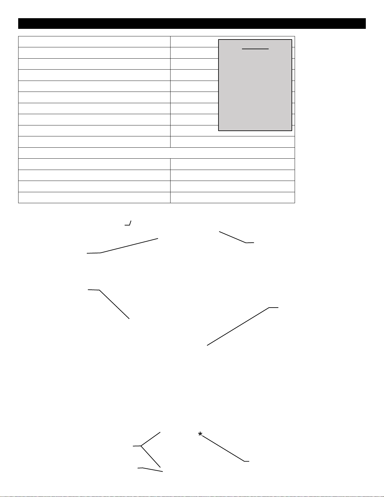
MQVL60 / MQVLBG60 Clearance to Combustibles
Front (Furniture, etc. from glass)
36” [92cm]
Side (from Stand-off) MQVL60
0” [0cm]
Side (from glass doors) MQVLBG60
18” [46cm]
Back (from Stand-offs)
0” [0cm]
Floor
0” [0cm]
Raised Hearth at Glass Opening
0” [0cm]
Minimum Ceiling Height (from bottom of fireplace)
76” [193cm]
Top (from Stand-offs)
0” [0cm]
Top of 90° Bend under 76” Enclosure
4” [10.2cm]
Top of 90° Bend over 76” Enclosure
4” [10.2cm]
VENTING SYSTEMS
Top of Horizontal Pipe
1/1/2” [3.8cm]
Side & Bottom of Horizontal Pipe
1” [2.5cm] All Vent Systems
Vertical Vent Pipe in Enclosure under 76”
4-9/16” [11.6cm] All Vent Systems
Vertical Vent Pipe in Enclosure over 76”
1” [2.5cm] All Vent Systems
No Framing on Top
Sides of fireplace
for MQVL60 Single
Side Units
Top opening of Chase
must be flush or within
3/4” of Enclosure Top
(
with
no grill, 220 sq. in.
with grill)
THIS AREA
MUST BE OPEN
MIN 550 Sq. In.
Bottom Air Opening Options – Min
102 sq. in.
Example: 1-1/2” x 68”
CEILING
76”
MIN
CEILING
Opening must not be
blocked by floor covering
Top of Enclosure
must be sealed so
that no heat can
escape.
⚠ NOTE
If using insulation in
vented chase (i.e. for
outside wall), wall board /
drywall is required to
support all insulation.
Vented chase must be
clean and free of all
debris (i.e. loose
insulation, pieces of
wood, etc.).
Maximum Total Depth
of TV Recess from
face of unit is 3-3/4”
17
MQVLBG60 SHOWN - SIDE VIEW
Min 200 sq. in.
Page 18
MQVL60 / MQVLBG60 Mantel Clearances
SIDE VIEW (MQVLBG60 Shown)
A Combustible Mantel
can be placed immediately
above the fireplace
opening.
A Combustible Hearth
can be placed immediately
below the fireplace
opening.
An Adjacent Side Wall
may project directly from
the side of the fireplace
opening.
MQVL60 / MQVLBG60 Adjacent Wall - TOP VIEW
Adjacent Wall- may project
directly from side of unit
Bottom Air Opening Options – Min 102sq in.
Example: 1-1/2” x 68”
This area must be open
MIN 550 Sq. In.
Min 200 Sq.
In. Free Air
28-1/2”
(55” TV)
15-1/4”
Fireplace Opening
VARIABLE
MQVLBG60
MQVL60 OR MQVLBG60
c/w VLBGK Corner Kit
Drywall
Opening must not be blocked by floor covering
18”
MIN
Adjacent Wall
18
Page 19
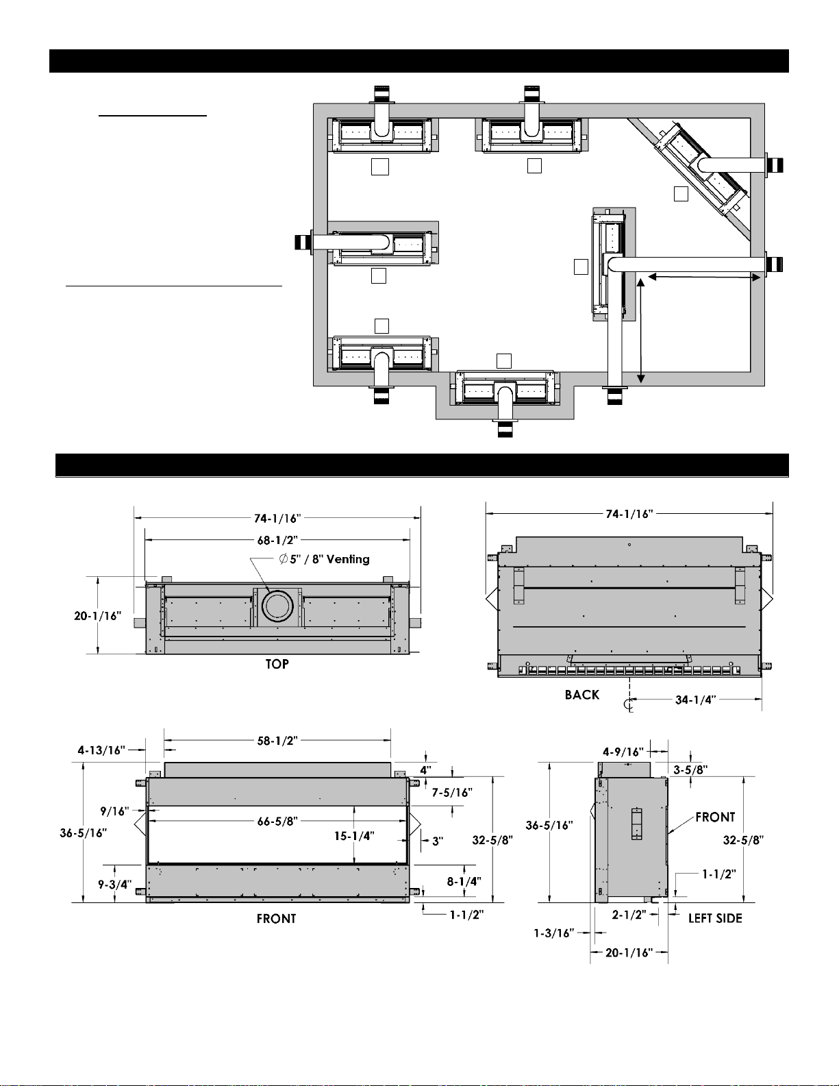
MQVL60 Single Side Locating Your Appliance
MQVL60 Single Side Fireplace Dimensions
A
G
C
D E F
20’ MAX
20’ MAX
B
19
LOCATION KEY:
A. Left Side Corner
B. Flat on Wall
C. 45° Corner
D. As a Room Divider
E. As an Island*
F. Right Side Corner
G. Exterior Wall Chase
*Island installation with a top vent is
possible as long as the horizontal
portion of the vent system does not
exceed 20 feet (6.1 m).
Page 20
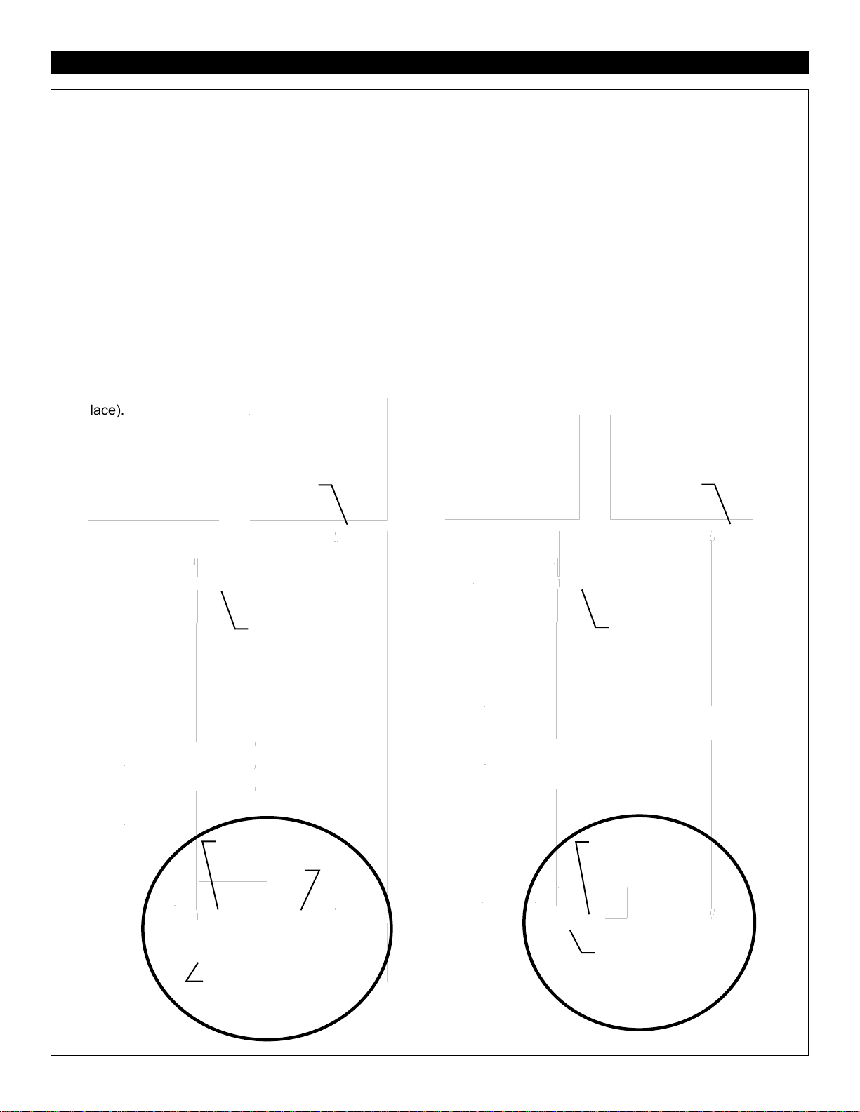
MQVL60 Single Side -Nailing Tab Guide-
These Nailing Tabs can be used in two ways:
1/2” Drywall Flush with Face of Fireplace –Fireplace
face and wall to be covered (e.g. Tile around
Fireplace).
Framing Flush with Face of Fireplace –Finished wall
surface will continue up to fireplace opening.
[Qty] 4 Nailing Tabs are located on each side of the front frame.
NOTE: If using the rear nailing tabs for cantilevered chase etc.,
refer to the Nailing Tab page for MQVLBG60 Bay Peninsula.
Pull up 90° for wall flush
with fireplace face.
Rotate 180° for framing
flush with fireplace face.
TOP VIEW
RIGHT SIDE
TOP VIEW
RIGHT SIDE
Flat
(As Shipped)
19-3/4”
Framing Depth
20-5/16”
Framing Depth
1
2
2
1
Facing Material
(Tile, marble, etc.)
Drywall
Nailing
Tab
Back
Wall
Drywall
Nailing
Tab
2
1
Nailing
Tab
Back
Wall
Nailing
Tab
20
Page 21
MQVL60 Single Side Framing
TOP VIEW
Appliance must be in place with venting connected before area above fireplace is framed in.
Fireplace Chase MUST BE VENTED with or without grills.
Fireplace Chase MUST BE VENTED at the top
with or without grills. Must have a minimum of
200 square inches free air opening.
Optional 60AVP Adjustable
Vented Platform shown.
FRAMING OVER FRONT TOP OF FIREPLACE
20-5/16” Framing
Flush with Face
BACK WALL
Double
Studs
Double
Studs
Framing Flush
with Face
Variable – Can be built
out to desired depth
FRAMING IN FRONT OF FIREPLACE
EXTENDED FRAMING IN FRONT OF FIREPLACE
⚠ DO NOT COVER
TOP OF PLATFORM.
21
Page 22
MQVL60 Single Side - Using Tile Lip
A Tile Lip is supplied for attachment above the fireplace opening. This can be used as a standard tile edging or as a mount
bracket for other surfaces like drywall or plywood. Set to desired height and attach through holes in face of fireplace.
Install before applying the finishing materials.
MQVL60 – Single Side -Facing Requirements
Unit may be covered with combustible material (i.e. drywall) up to the fireplace opening.
VL60EG or VL60EGS Grills can be used.
Drywall
Drywall
VALVE
IPI
SYSTEM
OPTIONAL
COMPONENTS
Do not drive screws into
these highlighted areas.
Option A: Open Chase at Ceiling (MIN 200 Sq. In.)
Option B: Vent Slot in Chase (MIN 200 Sq. In.)
Flush or within 3/4” of Enclosure Top
Lower Vent Slot MIN 102 Sq. In. is
REQUIRED for ALL Installations.
Example: 2” x 51”
Do not drive screws into
fireplace front. Facing
materials must be attached
to framing.
102 Square Inches Free Air Opening. Example: 1-1/2” x 68”
Opening must not be
blocked by floor covering
FRONT
OF
UNIT
NOTE: If installing VL60S1BL or SS Surround:
install Tile Lip using second hole from top, as
shown. This will provide the required 5/8”
clearance above opening.
5/8”
FOR
SURROUND
INSTALLATION
NOTE: If installing VL60S1BL or SS Surround:
5/8” Space is required around fireplace opening.
Do not allow wall covering to come within this area.
66-1/2”
22
Page 23
VL60S1BL / VL60S1SS -Surround Installation for MQVL60 -Option
NOTE: Install before applying the
finishing materials. Install Tile Lip
(supplied with fireplace) using second
hole from top, as shown. This will provide
the required 5/8” clearance above
opening.
ASSEMBLY: Attach Side Fillers and Bottom Filler to Surround Frame with [Qty] 11 screws.
Fireplace Finishing: 5/8” Space is required around fireplace opening. Do not allow wall covering to come within this area.
NOTE: DO NOT
OVERTIGHTEN SCREWS.
PARTS LIST:
- [Qty 1] Surround Frame
- [Qty 2] Black Side Fillers
- [Qty 1] Bottom Filler
- [Qty 1] Appliance Space Filler
- [Qty 15] #6 Black Screws
TILE LIP ON
FRONT OF
UNIT
5/8”
2nd hole
from top
Bottom Filler
Side Filler
Side Filler
Surround Frame
NOTE: If the wall covering material is
more than 3/4” thick, use the
Appliance Space Filler.
Install before applying the
finishing materials.
Appliance
Space Filler
5/8” Space
Screw
Screw
Screw
70-1/16”
1-1/2”
68-1/4”
23
Page 24
INSTALLATION:
- Fireplace must be installed
and wall surface must be
finished.
-Insert assembled Surround
into fireplace opening. [Qty 4]
Surround Tabs will fit into
[Qty 4] Fireplace Slots.
-Insert [Qty 4] screws through
the holes in the Surround
Tabs and into the Fireplace.
DO NOT TIGHTEN SCEWS.
-Set Surround to desired
depth (see Adjustment
below).
ADJUSTMENT:
-Depth of Surround can be
adjusted to match thickness
of wall finishing materials.
-Gap behind Surround can
be adjusted from
approximately 1/2” (drywall
only) to 2-1/4” (stone, brick,
or other materials).
-Once depth of Surround
has been set, tighten
screws to hold Surround in
place.
Surround Tabs
Fireplace Slots
Mounting Screws
Drywall
2-1/4” ADJUSTMENT
NOTE:
DO NOT OVERTIGHTEN
SCREWS.
1/2”
1-1/2”
2”
1/2”
Drywall
Stone, Brick, Etc.
24
Page 25
MQVL60 Single Side- MQVL48SEP Side Extension Panels -Option-
Framing Details:
Installation Procedure:
1. Place Panel into side opening of fireplace. Attach panels to inside of fireplace face with [Qty 2] #6 Black Screws.
2. Attach Panel to wall with nails or low profile pan head screws. Repeat for other side.
3. Proceed with finishing wall surface.
Contents if Kit:
Qty 2 – Side Extension Panels
Qty 4 - #6 Black Screws
4”
18-3/16”
19-7/16”
FINISHED
HEIGHT
FINISHED WIDTH
FROM EDGE OF
FIREPLACE TO
OUTSIDE OF 2 X 4
18-3/16”
PANEL
HEIGHT
19-3/16”
HORIZONTAL
FRAMING
DIMENSION
HORIZONTAL FRAMING ABOVE TOP OF
OPENING: 1/2”
HORIZONTAL FRAMING BELOW BOTTOM OF
OPENING: 7/16”
FINISHING OPTION
25
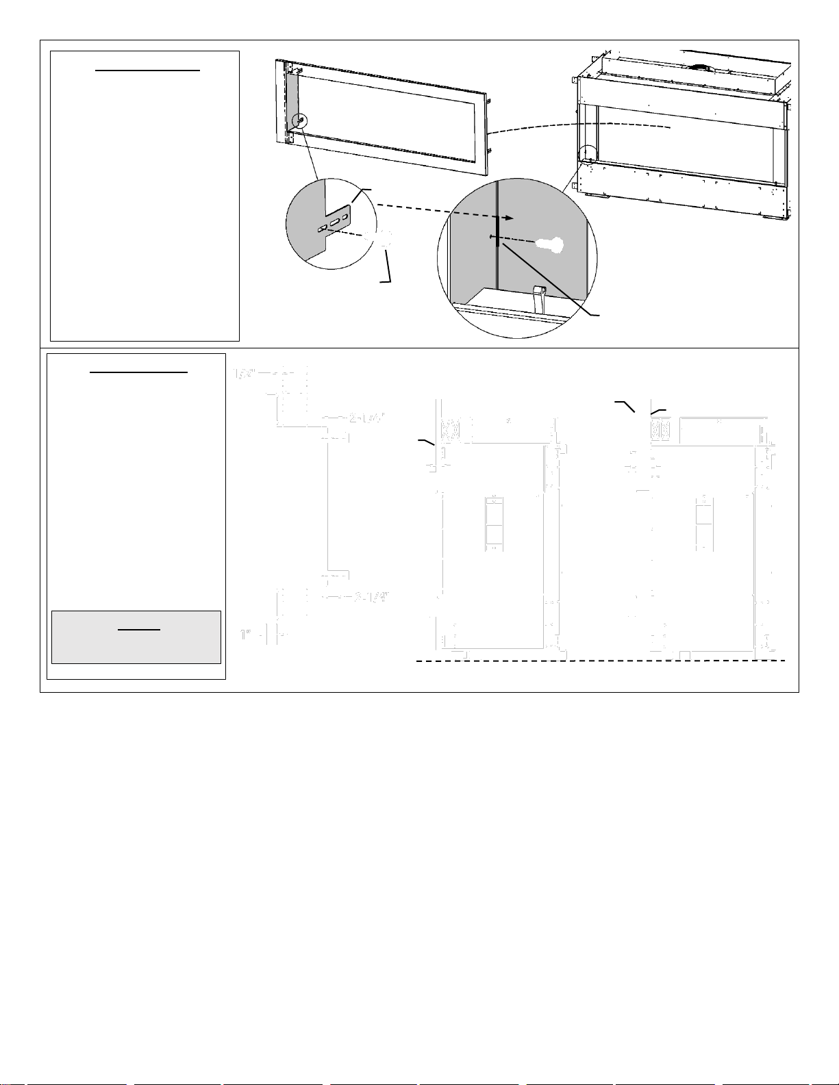
Page 26

MQVL60 Glass Front Removal / Installation
To remove Glass Front:
1. Remove the [Qty 4] Wing Nuts on the Upper Glass Retainer above the Glass Door Front and remove the Retainer.
2. Loosen the [Qty 4] Wing Nuts on the Lower Glass Retainer but do not remove.
3. Remove the Side Cover Panels.
4. Glass Door Front can now be lifted out of the fireplace.
5. Installation is the reverse of these steps. Tighten wing nuts on Glass Front until they are snug. Wingnuts should be finger-tight
on Glass Front.
NOTE: Do not over tighten nuts as glass could break.
Side Cover Panel
Upper Glass Retainer
X4
Ball of Gasket Faces Fireplace
Use caution when working with glass. Wear gloves. Suction Cups Recommended.
Side Cover Panel
26
Page 27

MQVLBG60 Bay Peninsula Locating Your Appliance
MQVLBG60 Bay Peninsula Fireplace Dimensions
A
B
C
F
20’ MAX
20’ MAX
G D E
⚠ IMPORTANT: Front corners of Firebox Glass must
have a dab of high-temp silicone placed between the
ball of the gasket and the glass. This will fully seal the
firebox corners.
27
LOCATION KEY:
A. Corner Kit- Left Side
B. Flat on Wall
C. Corner Kit- Right Side
D. Corner Kit- Left Side
E. Corner Kit- Right Side
F. 45° Corner
G. As an Island*
*Island installation with a top
vent is possible as long as the
horizontal portion of the vent
system does not exceed 20 feet
(6.1 m).
Page 28

MQVLBG60 Bay Peninsula -Framing
OPTION A: Framing Attached to Side of Fireplace- For building out around the fireplace. Framing must be self-supporting.
OPTION B: Framing Attached to Top of Fireplace- For
cantilevered chase. Framing must be self-supporting.
OPTION C: Framing Attached to Back of Fireplace- For
chase. Framing must be self-supporting.
Optional framing
attached to side
of fireplace
FRAMING ON TOP OF FIREPLACE
VARIABLE
Can be built
out to desired
depth
VARIABLE
TOP VIEW
RIGHT
SIDE VIEW
BACK WALL
20-5/16”
MIN
EXTENDED FRAMING IN FRONT OF FIREPLACE
TOP VIEW BACK WALL
LEFT SIDE VIEW
FRAMING ON TOP OF FIREPLACE
68-1/2” (WIDTH OF UNIT)
BACK WALL
BACK WALL
Sides of Unit
will be exposed
at viewing area.
This area must be open MIN 550 SQ. IN.
This area must be open
MIN 550 SQ. IN.
DOUBLE STUDS
DOUBLE
STUDS
DOUBLE
STUDS
DOUBLE
STUDS
DOUBLE
STUDS
DOUBLE
STUDS
DOUBLE
STUDS
DOUBLE
STUDS
20-5/16”
MIN
20-5/16”
MIN
FRAMING IN FRONT OF FIREPLACE
SINGLE
STUD
This area must be open
MIN 550 SQ. IN.
102 SQ. IN.
Required Bottom Chase Opening
102 SQ. IN.
Required Bottom
Chase Opening
RIGHT SIDE VIEW
102 SQ. IN.
Required Bottom
Chase Opening
28
Page 29

MQVLBG60 Peninsula –Nailing Tabs and Framing
OPTION A: Framing Attached to Side of Fireplace- For building out around the fireplace.
OPTION B: Framing Attached to Top of Fireplace- For cantilevered chase.
OPTION C: Framing Attached to Back of Fireplace- For cantilevered chase.
SIDE NAILING TAB
TOP NAILING
TAB
Optional framing
attached to side
of fireplace
Optional framing
attached to side
of fireplace
Optional framing
attached to side
of fireplace
Sides of Unit will be
exposed.
SIDE NAILING TAB
MIN. 102
SQ. IN.
MIN. 200
SQ. IN.
MIN. 200
SQ. IN.
MIN. 102
SQ. IN.
MIN. 200
SQ. IN.
MIN. 102
SQ. IN.
Optional VL60AVP
Shown.
⚠ DO NOT COVER TOP
OF PLATFORM.
Appliance and Framing are
NOT Load Bearing.
Appliance and Framing are
NOT Load Bearing.
Appliance and Framing are
NOT Load Bearing.
Air
Opening
Example: 2” X 51”
Air
Opening
Air
Opening
⚠ DO NOT COVER TOP
OF PLATFORM.
Example: 1-1/2” X 68”
⚠ DO NOT COVER TOP
OF PLATFORM.
Example: 2” X 51”
29
Page 30

VLBGCK - Corner Kit - for MQVLBG48/60/72 Peninsula Bay Option
- MUST BE INSTALLED BEFORE
UNIT IS INSTALLED INTO FRAMING.
- CORNER KIT CAN BE INSTALLED
AT EITHER END OF FIREPLACE.
⚠ Warning: Failure to position the parts in accordance with these
diagrams or failure to use only parts specifically approved with this
appliance may result in property damage or personal injury.
Contents of Kit:
Firebox Cover with Gasket - 1
Heat Shield with Standoff- 2
Inner Liner Panel - 3
Front Side Cover with Gasket- 4
90ml Tube Millpac
[Qty 22] 1/2” DT Screws
[Qty 6] Pan Head Screws
Preparation:
1. Remove the Side
Glass Door and
frame. NOTE: It is
not necessary to
remove the Spring
Mechanisms when
installing a Corner
Kit.
2. Remove Lower Front
Panel Assembly.
Remove Side Glass
Door from firebox
(Refer to Side Glass
Door Removal and
Installation). This
side glass door will
not be reused.
3. Remove Outer
Glass Supports
from side of fireplace.
These will not be
reused.
4. Cut Gasket just past
Corner Edge of
Firebox. Remove
Gasket from Side of
Firebox.
Remove Lower Front
Panel Assembly
SHEET METAL COMPONENTS:
1
2
3
4
Remove Side
Glass from
firebox.
Remove Outer
Glass Supports
Firebox Cover
Heat Shield
Inner Liner Panel
Cut Gasket just
past Corner
Edge of Firebox.
Remove Gasket
from Side of
Firebox
Side of
Firebox
30
Page 31

Installation:
1. Apply a small bead
of Millpac to Firebox
Cover Gasket. Insert
Firebox Cover into
place from front of
fireplace.
2. Use the 2 Location
Starter Holes in Top
and Bottom of
Firebox to position
Firebox Cover.
Fasten to firebox
using 1/2” DT Hex
Screws.
3. IF USING GLASS,
PORCELAIN, OR
FLUTED LINERS:
Remove [Qty 4] DT
Screws from the
outside and install
from the inside of the
firebox. IF
FIREPLACE IS
ALREADY
INSTALLED,
SIMPLY CUT
SCREWS WITH A
ROTARY TOOL
4. Place Heat Shield
into outside fireplace
opening. Fasten with
[Qty 7] 1/2” DT Hex
Screws, and [Qty 6]
Pan Head Screws
along front edge. Set
Stand-off into
position.
Use [Qty 7] DT
Screws to attach
Back, Top, and
Bottom of
Shield
Apply Mill-Pac
to Gasket of
Firebox Cover
Slide Firebox Cover Into Place From Front
IF USING
PORCELAIN OR
FLUTED LINERS:
Remove [Qty 4]
DT Screws from
outside and
install from inside
firebox.
IF FIREPLACE IS
ALREADY
INSTALLED,
SIMPLY CUT
SCREWS WITH A
ROTARY TOOL.
Use [Qty 6]
Pan Head
Screws to
attach Front
of
Shield
1
1
Do Not Apply
Mill-Pac to
Front Glass
Gasket
Do Not Apply
Mill-Pac to
Front Glass
Gasket
Heat Shield
Stand-off
Apply Millpac
to gasket
2
1
Use the 2 Location Starter
Holes at Top and Bottom
of Firebox.
Firebox
Cover
Lower Front
Panel Assembly
must be removed
DO NOT
STRIP
SCREWS.
CONTINUED ON NEXT PAGE
31
Heat
Heat
Page 32

Install Inner Liner
Panel:
NOTE: If you are
using a Firebox Back
Liner Kit (Glass,
Porcelain, or Fiber),
DO NOT INSTALL
Inner Liner Panel
from Corner Kit. A
(Glass, Porcelain, or
Fiber), Side Liner Kit
will also be required.
1. Remove and
discard Retainer
from False Bottom.
Keep Screws.
2. Install Inner Liner
Panel inside firebox
and secure with [Qty
3] DT Screws.
Install Side Cover
Panel
1. Install Side Cover
Panel when
installing Glass Front
Door.
2. Reinstall Lower Front
Panel Assembly.
Discard the [2] Outer
Glass Supports as
they are not required.
NOTE:
VLBGCK Corner Kit
Requires The Same
Framing And
Clearances As
MQVL48/60/72 Single
Side.
4
Install Inner Liner Panel and
secure with [Qty 3] DT Screws
Glass Side
Corner Kit side
MQVL48/60/72
Single Side.
3
3
Remove Retainer
from False
Bottom
Side Cover Panel
Lower Front
Panel Assembly
32
has the same
Installation
Clearances as
Page 33

MQVLBG60 Bay Peninsula - Using Tile Lip
MQVLBG60 Bay Peninsula -Facing Requirements
Unit may be covered with combustible material (i.e. drywall) up to the fireplace opening.
VL60EG or VL60EGS Grills can be used.
Drywall
Drywall
OPTIONAL
COMPONENTS
VALVE
IPI
SYSTEM
Option A: Open Chase at Ceiling
Minimum 200 Sq. Inches.
Option B: Vent Slot in Chase- Flush or within 3/4” of
Enclosure Top - Minimum 200 Sq. Inches.
Lower Vent Slot (MIN 102 Sq. In.) is REQUIRED for ALL Installations.
Example: 2” x 51”
Do not drive screws into
these highlighted areas.
Do not drive screws into
fireplace front. Facing
materials must be attached
to framing.
102 Square Inches Free Air Minimum
Example: 1-1/2” x 68”
66-1/2”
A Tile Lip is supplied for
attachment above the
fireplace opening. This can
be used as a standard tile
edging or as a mount
bracket for other surfaces
like drywall or plywood.
Set to desired height and
attach through holes in
face of fireplace.
33
Page 34

Enclave Series – Bay Peninsula Units- Front Glass Installation and Removal
To Install Glass Front:
1. Loosen Upper and Lower Side Glass
Retainer wing nuts until they are only
lightly snug (See A and B at right).
2. Place a bead of High Temp Silicone
on all four corners of the firebox
gasket (see above). This will seal
any gaps between where the gasket
and the glass corners meet.
3. Install Glass Front into the Lower
Glass Retainer. Install Upper Glass
Retainer. Tighten wing nuts until
lightly snug.
4. Match Glass Front up with Side
Glass at each end using Alignment
Tabs (See above).
5. Tighten wing nuts on Glass Front
until they are snug. Next, fully fingertighten wing nuts on Side Glass, and
then back them off 1/4 to 1/2 turn.
Finally, finish tightening all wing nuts
on Glass Front.
NOTE: Do not over tighten nuts as
glass could break.
Wingnuts should be finger-tight
on Glass Front.
To Remove Glass Front:
1. Remove the [Qty 4] Wing Nuts on
the Upper Glass Retainer and
remove the retainer.
2. Loosen the [Qty 4] Wing Nuts on the
Lower Glass Retainer but do not
remove. Glass Front can now be
lifted out of the fireplace.
⚠ IMPORTANT: Each corner must
have a dab of high-temp silicone
placed between the ball of the
gasket and the corner glass. This
will fully seal the firebox corners.
SILICONE
Front Glass is placed in front of
corner glass edge.
Upper Glass Retainer
X4
A: Upper Side Glass Retainer
B: Lower Side Glass Retainer
High Temp Silicone on
Firebox Gasket at corner
High Temp Silicone on
Firebox Gasket at corner
SILICONE
ALIGNMENT
TAB
34
Page 35

Enclave Series 48/60/72 – Bay Peninsula Units- – Side Glass Removal and Installation
Remove Front Firebox Glass first. If the Side Glass
Panel or another component must be cleaned or
replaced, remove the 4 Wing Nuts from the Side Glass
Door and remove Retainers, Glass Door Frame, and
Glass.
To Reinstall Side Glass Door:
1. Install Glass Door Frame onto firebox by engaging slots
in Door Frame behind the heads of the Carriage Bolts on
the upper and lower Spring Mechanisms.
2. Install Door Retainers and Wingnuts. Do not fully tighten
Wingnuts until Firebox Front Glass Panel is installed.
3. Proceed to Front Glass Installation Instruction.
Glass
48VLB-311
Spring Mechanism
60VLBG-126A
Replacement Part:
Spring Mechanism
60VLBG-126A
Glass Door Frame c/w Gasket
SIDE
GLASS
DOOR
Glass Door Frame c/w Gasket
48VLB-311A
Carriage Bolt
Carriage Bolt
SLOTS IN GLASS DOOR
FRAME WILL ENGAGE
BEHIND HEADS OF
CARRIAGE BOLTS.
Door Retainer
c/w Gasket
1/4-20 Wingnut [Qty 4]
Door Retainer
c/w Gasket
Spring Mechanism
60VLBG-126A
Slot in Glass
Door Frame
Slot in Glass
Door Frame
TOP
BOTTOM
⚠ IMPORTANT: Front corners must have a dab of high-
temp silicone placed between the ball of the gasket and
the glass. This will fully seal the firebox corners.
High Temp Silicone on Firebox
Gasket at corner
High Temp
Silicone on
Firebox Gasket
at corner
35
Page 36

Door and Glass Information MQVL60 / MQVLBG60
Glass Cleaning
⚠ Cautions and Warnings
Do not clean when the glass is hot.
The use of substitute glass will void all product warranties (see Glass Replacement in this section).
Care must be taken to avoid breakage of the glass.
Do not operate this fireplace without the glass front or with a broken glass front.
Do not strike or abuse the glass.
Round part of
gasket goes
toward firebox.
FIREBOX GLASS
Suction Cups Recommended
36
It will be necessary to clean the glass periodically. During startup, condensation, which is normal, forms on the inside of
the glass, and causes dust, lint etc. to cling to the glass surface.
Also, initial paint curing can deposit a slight film on the glass. It is therefore recommended that initially the glass be
cleaned two or three times with a fireplace glass cleaner. After that, the glass should be cleaned two or three times a
season depending on the circumstances.
Glass Replacement - Firebox
Only Robax ceramic or coated Neoceram glass may be used for replacement for all MQVL60 / MQVLBG60 Models. Glass
must be minimum 5mm thick. Be sure to purchase glass from an authorized dealer.
To replace glass, remove old gasket and clean glass. Peel backing from
new gasket and install as shown below.
Use caution when working with glass. Wear gloves.
Suction Cups Recommended.
Removal of the Glass Front: Refer to Glass Door Front Removal /
Installation section of this manual.
1. Remove nuts with a 3/8” wrench.
2. Remove Glass Door.
Removal of the Glass Side Doors: Refer to Glass Door Side Removal
section of this manual.
1. Remove nuts with a 3/8” wrench.
2. Remove Glass Door.
Glass Replacement – Safety Glass Barrier - MQVL60 / MQVLBG60 Models
Only Tempered Low E Glass may be used, and coated side of glass must face toward
firebox.
Be sure to purchase glass from an authorized dealer.
Refer to Glass Safety Barrier Installation / Removal section of this manual.
Use caution when working with glass. Wear gloves.
Suction Cups Recommended.
Page 37

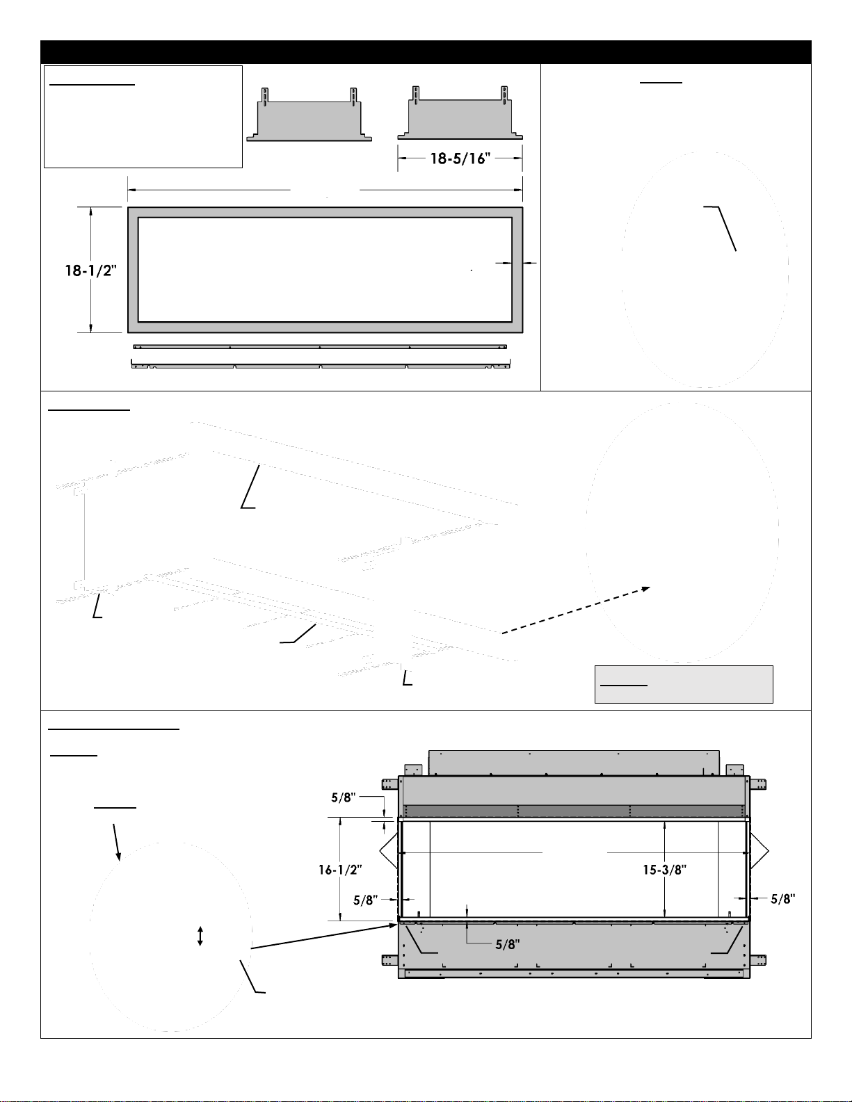
MQVL60 / MQVLBG60– Glass Safety Barrier Installation / Removal
INSTALL SIDE GLASS FIRST. DECAL ON GLASS SHOULD FACE OUTSIDE.
REPEAT PROCEDURE FOR FRONT GLASS. TWO PEOPLE AND / OR SUCTION CUPS ARE RECOMMENDED.
16-3/16”
14-3/8”
TOP
SIDE GLASS PANELS [QTY 2]
TOP
16-3/16”
66-5/8”
TOP
FRONT GLASS PANEL [QTY 1]
INSERT GLASS INTO CLIPS
IN TOP OF FIREPLACE
GLASS SUPPORTS
PLACE GLASS INTO GLASS
SUPPORTS. REPEAT FOR
OTHER SIDE.
37
Page 38

MQVL60 / MQVLBG60 Component Locations
DCHS Cover for Optional Remote Receiver- Millivolt or Proflame 1 Systems Only
P2
MODULE
LIGHT
DRIVER
(LED)
120 VAC
GAS LINE
120 VAC
OPTIONAL
PROFLAME 1
C/W REMOTE
RECEIVER &
DCHS BOX
Wall Mount Option
10ft. Extension Harness (Part No. 1001-P904SI)
required.
The Remote Receiver can be mounted
on a vertical wall stud using the DCHS as
a mounting bracket.
Ensure that the face is protruding 1/2” so
that the face plate will be flush on the
face of the wall.
Drywall cutout size is 2” wide by 4-1/8”
tall.
Must be installed within 10ft of valve
assembly (6ft recommended).
BATTERY
BACKUP
REMOTE PAIRING BUTTON
(SW1 SWITCH)
TOP VIEW
REMOTE PAIRING BUTTON
(SW1 SWITCH)
VALVE
38
Page 39

MQVL60 / MQVLBG60 LED Lighting
Please follow the current ANSI/NFPA 70 National Electrical Code in the USA and CAN/CSA C22.1 Canadian
National Electrical Code in Canada.
LED Light Strip is Located Under the Firebox.
TEMPERED
GLASS
PANELS
TEMPERED
GLASS
LED CONTROLLER
MODULE
BURNER PAN – TOP VIEW
FRONT OF FIREPLACE
YELLOW CONNECTOR
PROFLAME 2 MODULE
GROUNDING STUD
BATTERY BACKUP
LED LIGHT STRIP
584-X10 HARNESS
39
Page 40

VL60PLB Porcelain Back Liner Installation Option
STEP TWO: Remove Media Fence frim Media Tray with [Qty 3] Lower Liner Clips Attached.
STEP THREE:
Install one Liner
at each end of
the firebox.
Attach with 1 DT
Screw on top
corners and 2 at
bottom.
STEP FOUR: Install remaining Liner in Center Position in
firebox. Attach with 2 DT Screws on top and 2 at bottom.
STEP FIVE: Reinstall Media Fence as shown, with one row of slots exposed.
NOTE: Install
VL60PLB
Before
installing
MQVL48PLE
End Panel Kit.
CONTENTS:
PORCELAIN
BACK LINER X 3
BACK CLIP
(DISCARD)
MQVL60PLB - BACK PANEL KIT
STEP ONE: Remove Back
Clip and screws from inside
of firebox with a 1/4” hex
driver. Discard Back Clip
but Keep Screws.
DT SCREW
DT SCREW
MEDIA FENCE
-REQUIRED-
DO NOT
DISCARD
LOWER LINER CLIP
AT ENDS
LOWER LINER CLIP AT
CENTER
MEDIA FENCE
MEDIA FENCE
TOP CORNERS
BOTTOM CORNERS
TOP OF FIREBOX
⚠ Note: Discoloration
of Porcelain Liners Is
Not Covered Under
Warranty.
Glass Liners may
discolour during normal
operation of your
appliance.
This is normal, and not
considered a defect.
LOWER LINER CLIP (X3)
NOT REQUIRED
LOWER LINER
CLIP AT CENTERNOT REQUIRED
MEDIA FENCE
MEDIA FENCE
SLOTS
SLOTS
You are now ready to install VL48PLE if desired.
40
Page 41

VL48PLE Porcelain End Liner Installation Option
NOTE: If using VLBGCK CORNER KIT, DO NOT USE
Inner Liner Panel from Corner Kit. Remove if installed.
STEP ONE: Remove and discard
Liner Clips but Keep Screws.
NOTE: if you are using VLBGCK
CORNER KIT, only one End Panel
will be used.
STEP TWO: Insert Side Panel into
Firebox. Place Bottom against end
wall of Firebox and tilt into place.
Attach with DT Screws.
STEP THREE: Fasten top of panel
with One DT Screw.
⚠ Note: Warping and Discoloration of Porcelain or Painted
Metal Liners Is Not Covered Under Warranty.
Both Porcelain and Painted Metal Liners may discolour and
warp during normal operation of your appliance. This is normal,
and not considered a defect.
RIGHT
SIDE
END
PANEL
CONTENTS:
BACK LINER
X 2
LEFT
SIDE
END
PANEL
Remove and
Discard Liner Clip
-VL48PLE- END PANEL KIT
Porcelain Back Liners must be installed first.
Remove and
Discard Liner Clip
DT Screws
DT Screw
41
Page 42

MQVL60RGB Glass Back Liner Installation Option
STEP TWO: Remove Media Fence frim Media Tray with [Qty 3] Lower Liner Clips Attached.
STEP THREE:
Install one
Glass Back
Liner at each
end of the
firebox. Attach
with 1 DT
Screw on top
corners and 2 at
bottom.
STEP FOUR: Install remaining Glass Back Liner in Center
Position in firebox. Attach with 2 DT Screws on top and 2 at
bottom.
STEP FIVE: Reinstall Media Fence as shown, with one row of slots exposed.
NOTE: Install
MQVL60RGB
Before
installing
MQVL48RGE
End Panel Kit.
CONTENTS:
GLASS BACK
LINER X 3
BACK CLIP
(DISCARD)
MQVL60RGB - BACK PANEL KIT
⚠ CAUTION
-NOT TEMPERED GLASS-
-EXTREMELY FRAGILE-
– HANDLE WITH CARE-
STEP ONE: Remove Liner
Clip and screws from inside
of firebox with a 1/4” hex
driver. Discard Back Clip
but Keep Screws.
DT SCREW
DT SCREW
MEDIA FENCE
LOWER LINER CLIP
AT ENDS
LOWER LINER CLIP AT
CENTER
MEDIA FENCE
MEDIA FENCE
TOP CORNERS
BOTTOM CORNERS
TOP OF FIREBOX
⚠ Note: Discoloration
of Glass Liners Is Not
Covered Under
Warranty.
Glass Liners may
discolour during normal
operation of your
appliance.
This is normal, and not
considered a defect.
LOWER LINER CLIP (X3)
NOT REQUIRED
LOWER LINER CLIP AT
ENDS- NOT REQUIRED
LOWER LINER
CLIP AT CENTERNOT REQUIRED
MEDIA FENCE
MEDIA FENCE
SLOTS
SLOTS
You are now ready to install MQVL48RGE if desired.
42
Page 43

MQVL48RGE Glass End Panel Installation Option
STEP ONE: Insert Left Panel into firebox. Tilt top of panel
against left side wall of firebox.
STEP TWO: Lift panel in order to place slot in End Panel
over Flange on False Bottom.
NOTE: Back Glass Liners must be installed first.
RIGHT
SIDE
GLASS
END
PANEL
LEFT
SIDE
GLASS
END
PANEL
-MQVL48RGE - END PANEL KIT
⚠ CAUTION – NOT TEMPERED GLASS-
EXTREMELY FRAGILE – HANDLE WITH CARE
NOTE: If using VLBGCK CORNER KIT and you are NOT installing
a Glass End Panel, install Inner Liner Panel from Corner Kit before
Glass Back Liner. However, if you ARE installing a Glass End
Panel, do not install Inner Liner Panel from the Corner Kit.
PANEL
SLOT
FALSE BOTTOM
FLANGE
GLASS
LIFT AND PUSH
CONTINUED ON NEXT PAGE
NOTE: If using with
VLBGCK Corner
Kit, Metal Tab
behind Panel Slot
must be cut off or
Bend inward 90°.
43
Page 44

STEP THREE:
Engage Front Slot of Tab with DT Screw in side wall of firebox. There is no bottom attachment Screw.
Repeat actions for other side.
NOTE: if you are using VLBGCK CORNER KIT, only one End Panel will be used.
⚠ Note: Discoloration of Glass Liners Is Not Covered Under Warranty.
Glass Liners may discolour during normal operation of your appliance.
This is normal, and not considered a defect.
LEFT SIDE
END PANEL
TAB
FRONT
OF
FIREBOX
44
Page 45

MQVL60RLSB / MQVL48RLSE Stacked Brick Liner Installation Option
MQVL60RLFB / MQVL48RLFE Fluted Liner Installation Option
STEP TWO: Remove Media Fence frim Media Tray with [Qty 3] Lower Liner Clips Attached.
STEP THREE: Install Back Liners.
Step Five Reference Drawing
NOTE: If using VLBGCK CORNER KIT, remove Inner Liner Panel
from Corner Kit if installed.
STEP ONE: Prepare the fireplace.
Remove Upper Liner Clips from inside of firebox with a 1/4” hex driver.
Reinstall Back Clip with [Qty 2] DT
Screws.
RIGHT
SIDE
END
PANEL
BACK LINER
X 2
LEFT
SIDE
END
PANEL
RIGHT SIDE
END PANEL
MQVLBG60 WITH
VLBGCK CORNER
KIT SHOWN
END CLIP
BACK CLIP
END CLIP
-MQVL48RLSE- END LINER KIT
-MQVL60RLSB- BACK LINER KIT
BEND END CLIP
INTO SHAPE
REINSTALL INTO
SAME HOLE IN
FIREBOX
Liners are
Identical
No Left or
Right
MEDIA FENCE
LOWER LINER CLIP (X3)
LOWER LINER CLIP
AT ENDS
MEDIA FENCE
MEDIA FENCE
LOWER LINER CLIP
AT CENTER
MEDIA TRAY
MEDIA FENCE
BACK CLIP
- CONTINUED ON NEXT PAGE -
45
Page 46

STEP FOUR: Install Lower Liner Clips [x3]. Reinstall Media Fence as shown, with one row of slots exposed.
STEP FIVE: Install Side Liners. Reinstall End Clips with DT Screws.
See Step Five Reference Drawing on Previous Page.
⚠ Note: Discoloration of Liners Is Not Covered Under Warranty.
Liners may discolor during normal operation of your appliance. This is normal, and not considered a defect.
LOWER LINER CLIP (X3)
MEDIA FENCE
LOWER LINER
CLIP AT ENDS
MEDIA FENCE
LOWER LINER
CLIP AT CENTER
SLOTS
SLOTS
46
Page 47

MQVL60 / MQVLBG60 MQ Dealer Accessories
ACCESSORY ITEM
DESCRIPTION
CRUSHED GLASS MEDIA
Spread the glass embers onto the false bottom and burner.
Ensure the glass embers do not excessively overlap as this will affect
the flame pattern. Use care when placing glass embers near the pilot
area so as not block or have the glass fall over the crossover holes
from the pilot to the burner, as delayed ignition can occur.
The following types of glass are approved:
½” Ember Glass Material from American Fireglass.
Maximum amount: Natural Gas is 15 lbs, Propane units 10 lbs.
Liquid Glass from Firegear.
Maximum amount: Natural gas is 15 lbs, not recommended for
Propane appliances.
MQG5C
Decorative Ember Glass –Bronze
MQG5W
Decorative Glass 1/2” White
MQG5A
Decorative Ember Glass Cobalt Blue
MQG5B
Decorative Ember Glass - Black
MQG5ZG
Decorative Glass- Zircon Glacier Ice
Use of any other glass can alter the performance of the
unit and is not covered under warranty.
Discoloration of Glass Media may occur if placed on the
burner, this is not covered under warranty.
*Pilot Shield should be visually inspected
WARNING
Pilot Area Must Not Be Covered,
as delayed ignition can occur.
Do not change or substitute the
glass ember material provided with
this fireplace. If replacing, use only
replacement glass embers
available from your local
authorized dealer.
1
2
3
NOTE
Pilot Area Must Not Be
Covered, as delayed
ignition can occur.
Do Not Cover any part of
the burner tube with logs
as sooting may occur.
For best flame pattern it
is essential to spread
supplied 1/2” Crushed
Glass or MQEMBER
chunks directly onto
burner tube.
Fill area between Media Fences Only with a
single layer of crushed glass. Do not over fill.
Pilot Area Must Not
Be Covered
47
The following Accessories are available through MQ Dealers only.
monthly for signs of deterioration due to
flame exposure. Replace if necessary.
MQ46D Driftwood Log Set- 3pcs.
Place Log 1 on left side of fireplace against the back wall of the firebox.
Place Log 2 on the right side of fireplace against the back wall of the firebox and onto Log 1 as shown.
Place Log 3 in front of the burner in the center of fireplace as shown.
Can be used with MQ Glass, MQ Rock, MQ Stone or MQ Ember. Follow instructions for these accessories.
Page 48

NOTE
Pilot Area Must Not Be Covered, as delayed ignition can occur.
Do Not Cover any part of the burner tube with logs as sooting may occur.
For best flame pattern it is essential to spread supplied Bronze Glass directly onto burner tube.
MQRBD1
MQRock2
Or
MQRock3
48
MQROCK2, MQROCK3, MQRBD1 - Place rocks randomly onto False Bottom.
MQ STONE DECORATIVE STONE SET- Place Stones onto False Bottom randomly. Do Not cover Pilot Area.
Not all stones will be used on some models.
MQEMBER- Place these glowing ember chunks randomly. Embers may be used with or without other accessories.
Page 49

MQRBD3 -5 Piece Driftwood Log Set- OPTION
Can be used with MQ Glass, MQ Rock, MQ Stone or MQ Ember. Follow instructions for these accessories.
LOG 1
LOG 2
LOG 5
LOG 3
LOG 4
LOG 1
LOG 1
LOG 2
LOG 2
LOG 3
LOG 3
LOG 4
LOG 4
LOG 5
LOG 5
⚠ NOTE
For best flame pattern it
is essential to spread
supplied Crushed Glass
or MQEMBER directly
onto burner tube.
If sooting occurs, one or
more logs may be
removed.
LOG 1
LOG 4
LOG 2
LOG 5
LOG 3
LOG 1
LOG 3
LOG 2
LOG 5
LOG 4
- Logs as Shipped -
Setup Option 1 – Top View
Setup Option 1- Front View
Setup Option 2 – Top View
Setup Option 2 Front View
49
Page 50

Enclave Series MQLOGF48D OPTION
Enclave Series MQRBBW OPTION
2
1 3 4 5 6
1
3
4
5
4
3
2
1
5
6
Can be used with MQ
Glass, MQ Rock, MQ
Stone or MQ Ember.
Follow instructions for
these accessories.
1 4 3
2
⚠ NOTE
Pilot area must not be covered,
as delayed ignition could occur
For best flame pattern it is
essential to spread supplied
Crushed Glass or MQEMBER
directly onto burner tube.
If sooting occurs, one or more
logs may be moved.
2
5
50
Page 51

MQVL60 / MQVLBG60 Gas Line
MODELS
MQVL60N
MQVL60NE
MQVL60NE2
MQVL60LP
MQVL60LPE
MQVL60LPE2
MQVLBG60N
MQVLBG60NE
MQVLBG60NE2
MQVLBG60LP
MQVLBG60LPE
MQVLBG60LPE2
Fuel
Natural
Propane
Natural
Propane
Gas
Control
Millivolt / IPI
Millivolt / IPI
Millivolt / IPI
Millivolt / IPI
INPUT
Maximum
45,000 BTU
44,000 BTU
45,000 BTU
44,000 BTU
Low
29,000 BTU
34,000 BTU
29,000 BTU
34,000 BTU
Orifice
Size
(0-4500ft)
#29
#46
#29
#46
Air Shutter
1/8”
Fully Open
1/8”
Fully Open
Gas Inlet Size S.I.T. 820 Nova, 3/8” NPT
Gas Supply Pressure
Minimum
Normal
Maximum
Natural Gas
5”
7”
9” Propane
11”
11”
12” Manifold Pressure
Natural Gas
Propane
Manifold Pressure High
3.5 IN. W.C./.87 KPa
10 IN. W.C./2.61 KPa
Manifold Pressure Low
1.6 IN. W.C./.40 KPa
6.3 IN. W.C./1.57 KPa
3/8” UNION
1/2” X 3/8” SHUTOFF
VALVE
3/8” NIPPLE
1/2” GAS SUPPLY
NOTE: The gas line connection may be made of 1/2” rigid pipe or an Approved Kingsman Flex Connector, such as FP15GC.
Since some municipalities have additional local codes, it is always best to consult your local authorities and the current CAN/CGA -
B149.1 or .2 installation code in Canada or the National Fuel Gas code ANSI Z223.1 in the U.S.A
Important:
Always check for gas leaks
with
a
soap and water solution. Do not use
open
flame
for leak
testing.
For the state of Massachusetts a
T-handle
gas
shut-off valve must be used on a gas
appliance. This T-handle gas shut-off valve
must be listed and approved by the state of
Massachusetts. This is in reference to the state
of Massachusetts state code CMR238.
51
Installation
This gas appliance should be installed by a qualified installer in accordance with local building codes and with current CAN/CGA B149.1 or .2 installation codes for Gas Burning appliances and equipment in Canada and the National Fuel Gas Code ANSI Z223 in
the U.S.A.
1. The gas pipeline can be brought in through
either the right or the left side of the appliance.
A knockout is provided at either location to allow
for the gas pipe installation and testing of any
gas connection.
2. The gas control inlet is 3/8” NPT. Typical
installation layout for rigid pipe is shown at right.
3. When using copper or flex connector, use
only approved fittings. Always provide a union
so that gas line can be easily disconnected for
burner or fan servicing. See gas specification for
pressure details and ratings.
4. When a vertical section of gas pipe is
required for the installation, a condensation trap
is needed. See CAN/CGA-B149.1 or .2 for code
details.
5. For natural gas, a minimum of 3/8” iron pipe with gas minimum pressure of 4.5” w.c. must be used for supply from the gas meter.
Consult with the local gas utility if any questions arise concerning pipe sizes.
6. A 1/8” NPT plugged tappings are accessible for test gauge connection both on the inlet and outlet of the gas valve.
7. Turn the gas supply ON and check for leaks. DO NOT USE OPEN FLAME FOR THIS PURPOSE. Use an approved leak testing
solution.
8. The appliance and its individual shutoff valve must be disconnected from the gas supply piping system during any pressure
testing of that system at test pressures in excess of 1/2 PSIG (3.5 KPa).
9. The appliance must be isolated from the gas supply piping system by closing its individual shutoff valve during any pressure
testing of the gas sup- ply piping system at test pressures equal to or less than 1/2 PSIG (3.5 KPa).
Gas Specifications
Page 52

Millivolt System, Lighting, and Burner Control
FOR YOUR SAFETY READ BEFORE LIGHTING
BEFORE LIGHTING
A This appliance has a pilot which must be lighted by hand. When
lighting the pilot, follow these instructions exactly.
B Smell all around the appliance area for gas. Be sure to smell next
to the floor because some gas is heavier than air and will settle on
the floor.
WHAT TO DO IF YOU SMELL GAS
Do not try to light an appliance.
Do not touch any electrical switch; do not use any phone in your
building.
Immediately call your gas supplier from a neighbour’s phone. Follow the
gas supplier’s instructions.
If you cannot reach your gas supplier, call the fire department.
C Use only your hand to push or turn the gas control knob. Never use
tools. If the knob will not push in or turn by hand, don’t try to repair it.
Call a qualified technician. Force or attempted repair may result in a fire
or explosion.
D Do not use the appliance if any part has been under water. Immediately
call a qualified service technician to inspect the appliance and to
replace any part of the control system which has been under water.
LIGHTING INSTRUCTIONS
1. Stop! Read the safety information above this label.
2. Set the thermostat to lowest setting.
3. Turn off all electrical power to the appliance.
4. Locate valve under the burner assembly.
5. If the control knob is not already in the off position, i.e. the word
“OFF” in the 9 o’clock position, then push in the gas control knob
slightly and turn clockwise to “OFF”. NOTE: Knob cannot be
turned from “PILOT” to “OFF” unless knob is pushed in slightly. Do
not use force.
6. Wait five [5] minutes to clear out any gas. If you then smell gas.
STOP! Follow “B” in the safety information above on this label. If
you don’t smell gas then go to the next step.
7. Now push in the control knob slightly and turn counter-clockwise
to the “PILOT” position.
8. Push in the control knob all the way and hold it. With the other
hand push in the red igniter button until you hear a click. Now
observe closely the pilot burner located on the rear center-left
hand side of the main burner.
If a flame has appeared then continue to depress the control knob for 20
seconds. If the flame did not appear then continue to depress the red
igniter button every 5 seconds until a flame is established. NOTE: If
after 30 seconds a flame has not yet been established then turn the
control knob back to the off position and repeat steps 5, 6 & 7.
9. Once the pilot has been established hold the control knob in the
depressed position for approximately 25 seconds before releasing. If
the flame goes out then repeat steps 7 and 8.
If the knob does not pop up when released, stop and immediately call
your service technician or gas supplier.
If the pilot will not stay lit after several tries, turn the gas control to
“OFF” and call your service technician.
10. Now turn the control knob to the “ON” position. The burner will not light
unless the wall switch thermostat or remote control is turned “ON” or in
the case of the thermostat there is a call for heat.
11. Close the access door and turn all electrical power back to the
appliance.
12. The pilot must be turned off when the unit is not in use.
TO TURN OFF THE APPLIANCE
1. Set the thermostat to lowest setting.
2. Turn off all electric power to the appliance if service is to be
performed.
3. Open the control access door.
4. Push in the gas control knob slightly and turn clockwise to the “OFF”
position. Do not force.
5. Replace control access panel.
Recommended Maximum Lead Length (Double Wire)
When Using Wall Switch or Thermostat
Wire Size
Max. Length
14ga
100ft [30.4m]
16ga
64ft [19.5m]
18ga
40ft [12.1m]
20ga
25ft [7.6m]
22ga
15ft [4.5m]
CAUTION: DO NOT WIRE 120V POWER TO
MILLIVOLT SWITCHES OR THERMOSTAT.
NOTE: Only one on/off device (manual on/off, remote control, or hard wired thermostat) should be connected to the
appliance at any one time, this is most important when installing an insert or stove as the on/off rocker switch is installed at
the factory.
WARNING: If you do not follow these instructions exactly, a fire or explosion may result causing property
damage, personal injury or loss of life.
To Wall Switch,
Thermostat*, Or
Remote Receiver
52
Page 53

Troubleshooting the Gas Control System
⚠ WARNING
BEFORE DOING ANY GAS CONTROL SERVICE WORK, REMOVE THE GLASS FRONT.
NOTE: Before troubleshooting the gas control system, be sure external gas shut off is in the "On" position.
Problem
Possible Causes
Corrective Action
Spark igniter will not
light.
Defective or misaligned
electrode at pilot.
Check for spark at electrode and pilot: if no spark and electrode wire is
properly connected, replace igniter.
Defective igniter (pushbutton).
Using a match, light pilot. If pilot lights, turn off pilot and push the red
button again. If pilot will not light - check gap at electrode and pilot
should be 1/8" to 1/4" to have a strong spark.
Pilot will not stay lit after
carefully following
lighting instructions.
Defective thermocouple
(flame switch where
applicable).
Check pilot flame. Must impinge on generator and thermocouple. Clean
and/or adjust pilot for maximum flame impingement on generator and
thermocouple. Replace thermocouple if pilot will not hold. (Hand tight
1/8 turn on replacement)
Defective valve magnet.
Replace valve, if pilot won't hold after the thermocouple is replaced.
Pilot burning, no gas to
burner, valve knob “ON”,
and wall switch “ON”.
Wall switch or wires
defective.
Check wall switch and wires for proper connections. Jumper wire
across terminals at wall switch. If burner comes on, replace defective
wall switch. If okay, jumper wires, across wall switch wires at valve. If
burner comes on, wires are faulty or connections are bad.
Generator may not be
generating sufficient
voltage.
Check generator with millivolt meter. Take reading at generator
terminals of gas valve. Should read 325 millivolts minimum while
holding valve knob depressed in pilot position and wall switch "off"
Replace faulty generator if reading is below specified minimum.
Plugged burner orifice.
Check burner orifice for stoppage and remove.
Defective automatic valve
operator.
Remove wall switch wires from gas valve. Install jumper wires from top
bottom terminals of gas valve. Turn valve on "ON". If main burner does
not light, replace valve.
Frequent pilot outage
problem.
Pilot flame may be too low
or blowing (high) causing
the pilot safety to drop out.
Clean and/or adjust pilot flame for maximum flame impingement on
generator and thermocouple.
*See NOTE below – Seven Day Timer
Flame lifts off burner
and goes out in less
than 30 seconds.
Inner 4” liner has come off
flue or termination, flame is
starving for oxygen.
Attach 4" liner to flue or termination using screws, silicone and clamps
as stated in manual.
Flame lifts off burner on
one side while the rest
of the flame remains lit.
Improper installation of
firebrick. Firebrick is likely
leaning.
Be sure to position firebrick against firebox walls and be sure to use
brick clips attached to the inner side of firebox.
*NOTE: The pilot system for this appliance may be equipped with a Seven Day Timer, in which case the pilot flame will
be extinguished if the main burner has not been turned ON for seven days.
This Seven Day Cycle is reset every time the main burner is cycled ON / OFF and the pilot remains lit.
If more than seven days has passed since the main burner has been cycled ON / OFF and the pilot is also out, follow
the procedures described in this manual to light the pilot.
53
Page 54

Annual Inspection List for Determining Safe Operation of a Direct Vent Gas Fireplace
Refer to this checklist for proper maintenance, safe use, and operation.
See each section for more specific information.
1. Inspect and operate all pressure relief mechanisms (i.e., relief dampers, spring loaded door latches) installed
on your appliance to verify relief mechanisms are free from obstruction to operate.
2. Clean glass window with a suitable fireplace glass cleaner. Abrasive cleaners must not be used. Be careful not
to scratch the glass when cleaning.
3. Inspect the operation of the Pilot. Ensure that it is working properly.
4. Inspect and ensure the lighting of the main burner occurs within 4 seconds of
the main gas valve opening. Visual inspection should match that outlined in
the appliance instruction manual (refer to Monthly Flame Inspection).
Inspect primary air openings for blockage.
5. Inspect condition of vent and vent terminal for sooting or obstruction and correct if present.
6. Vacuum and clean any debris in the firebox that is not supposed to be there.
7. Test and measure the flame failure response time of the flame safety system. It must de-energize the safety
shutoff in no more than 30 seconds.
Procedure for Millivolt Units: Turn on fireplace for 5 minutes. Shut off fireplace while listening to valve. A
“click” should be heard within 30 seconds. This indicates the safety shutoff is working properly.
Procedure for IPI Units: Turn on fireplace and allow main burner to come on. Then disconnect Flame Sense
wire from IPI Module (X3 Connection). The fireplace should shut down immediately.
8. Check all accessible gas-carrying tubes, connections, pipes and other components for leaks.
Upper Damper
Upper Damper
Lower Damper
Upper Door Latch
Lower Door Latch
Relief Dampers inside
Firebox should open
and close freely.
Spring loaded Door Latches should
extend and return to the closed position.
Inspect Pilot Flame
Pilot Orientation
(Top View)
Burner
Primary Air Opening
Inspect for Blockage
54
Page 55

Burner System Maintenance MQVL60 / MQVLBG60
It is recommended to annually inspect and clean the Burner System to prevent malfunction and / or sooting. This operation
⚠ -CAUTION-
Before servicing the burner system ensure that the gas supply is turned OFF and disconnect all electrical
connections to the appliance. Allow the appliance to cool to room temperature. Note that the pilot assembly
may be hot in an intermittent or standing-pilot system—even if the main burner was never on. Exercise
caution when working within the area.
-ALL WORK SHOULD BE PERFORMED BY A QUALIFIED AND CERTIFIED TECHNICIANPilot Area Must Not Be Covered.
Pilot Must Maintain This
Relationship With Burner.
*Pilot Shield should be visually inspected monthly
for signs of deterioration due to flame exposure.
Replace if necessary.
55
should be performed by your dealer or a qualified technician.
Monthly Flame Inspection
It is recommended to turn on the unit at least once a month and inspect the flame pattern to ensure there are no problems with
the burner tube (Flame should appear similar to the above picture).
The pilot flame should also be inspected monthly to ensure proper operation.
Page 56

Gas Conversion Part A MQVL60 / MQVLBG60
Models: MQVL60N, MQVL60NE, MQVL60NE2, MQVL60LP, MQVL60LPE, MQVL60LPE2, MQVLBG60N, MQVLBG60NE,
Kit Number
Description
Pilot Orifice
Burner Orifice
Brass (1000-255)
Brass Nipple
Air
Shutter
Hi/Lo
Regulator
60VL-CKLP
Propane Conversion
-Millivolt-
1001-P167SI
#30 (977.167)
#46
1000-253
Closed
Fully open
1001-P202SI
(0.907.202)
60VL-CKNG
NG Conversion
-Millivolt-
1001-P165SI
#51 (977.165)
#29
1000-253
Closed
1/8”
1001-P201SI
(0.907.201)
60VL-CKLPI
Propane Conversion
-IPI-
1001-P168SI
#35 (977.168)
#46
1000-253
Closed
Fully open
1002-P014SI
(0.907.014)
60VL-CKNGI
NG Conversion
-IPI-
1001-P166SI
#62 (977.166)
#29
1000-253
Closed
1/8”
1002-P016SI
(0.907.016)
60VL-CKLP2
Propane Conversion
-IPI-
1001-P168SI
#35 (977.168)
#46
1000-253
Closed
Fully open
1002-P012SI
(907.012)
60VL-CKNG2
NG Conversion
-IPI-
1001-P166SI
#62 (977.166)
#29
1000-253
Closed
1/8”
1002-P013SI
(907.013)
IMPORTANT: Always check for gas leaks with a soap and water solution. DO NOT USE OPEN FLAME FOR LEAK TESTING.
⚠ Caution:
The gas supply shall be shut off prior to disconnecting the electrical power, before proceeding with the conversion.
1. The Burner Tube must be removed from the Burner Pan Assembly (See Burner Tube
Removal). Adjust the Air Shutter to the correct Primary Air setting as specified in the
manual or on the label plate. To adjust the Primary Air setting, loosen screw on the side of
the Air Shutter and rotate to the correct opening using a drill bit or tape measure. Retighten
screw.
2. Remove the Main Orifices using a ½” wrench and replace with the new Conversion Orifices
which came with the Conversion Kit.
3. Replace the Burner Tube. Install the new Pilot Orifice (See Pilot Conversion) and Hi/Lo
valve regulator by following instructions supplied with the Conversion Kit.
Refer to “Gas Specifications Chart” for inlet pressures and input ratings. Clock meter to verify input rate. Place conversion label as close
to converted gas control as possible. Refer to lighting instructions to verify the normal operating sequence of the ignition system.
⚠ -Warning-
This conversion kit shall be installed by a qualified service agency in accordance with the manufacturer's instructions and all applicable
codes and requirements of the authority having jurisdiction. If the information in these instructions is not followed exactly, a fire, explosion
or production of carbon monoxide may result causing property damage, personal injury or loss of life. The qualified service agency is
responsible for the proper installation of this kit. The installation is not proper and complete until the operation of the converted appliance
is checked as specified in the manufacturer's instructions supplied with the kit.
Pilot Must Maintain This
Relationship With Burner.
Burner Mount
Valve
Pilot
Air Shutter
Burner
Orifice
Parts List:
HI/LO Pressure
Regulator Assembly
Pilot Orifices
[1] Burner Orifice
[1] Brass Nipple
Instructions
Conversion Kit Label
Pilot
Air Shutter
Access Plate
56
MQVLBG60NE2, MQVLBG60LP, MQVLBG60LPE, MQVLBG60LPE2
Page 57

Gas Conversion for Top Convertible Pilot – Part B (series 0190XYZ)
Instructions for converting SIT 190 series pilot burner injector from NG to LPG and from LPG to NG only.
This information should be considered as supplemental to the Appliance Manufacturer's Instructions.
WARNING!
The installation of this conversion kit must only be undertaken by a qualified and certified gas appliance
installer.
WARNING!
This conversion kit must ONLY be applied as part of a conversion kit supplied by the APPLIANCE
MANUFACTURER for the specific appliance, and type of gas, being converted.
SIT GROUP
w w w . s i t g r o u p . i t
57
1. Shut-off the gas supply to the appliance.
2. Allow the pilot burner to cool to room temperature.
WARNING: Touching a hot pilot burner can
result in injury.
3. The pilot hood is held in place by spring. First
remove the spring, then remove the hood by pulling
it up from the pilot bracket (fig. 1).
4. Insert a 5/32" or 4 mm Allen wrench into the
hexagonal key-way of the injector (fig. 2), and
rotate it counter-clockwise until it is free of the
injector journal.
5. Verify that the new injector is proper for the
application. The injector size is stamped on the
side of the injector near the top. LPG injectors have
a groove machined around their circumference
near the top, while NG injectors do not have a
groove (fig. 4). Refer to the Appliance
Manufacturer’s instruction sheet for the proper
injector size.
6. Insert the Allen wrench into the end of the injector.
Then, insert the injector into injector journal, and
rotate the injector clockwise until a torque of 9 lbf in
(1.0 Nm) is achieved.
7. First replace the pilot hood by aligning the tab on
the base of the hood with the slot in the side of the
pilot journal, and push the hood down, onto the
pilot bracket (fig. 3). The hood must sit squarely on
the bracket for proper operation. Then replace the
spring by pushing it on his seat (fig.3). Check to
insure that the hood is properly seated onto the
pilot bracket and that the spring is properly inserted
onto his seat.
8. Restore the gas supply to the appliance, and ignite
the pilot burner. Verify proper ignition and
operation.
Page 58

Gas Conversion for Modulator – PART C
58
Page 59

MQVL60 / MQVLBG60 False Bottom Removal (Media Tray)
In order to access the Burner Tube and Burner Pan, the False Bottom must be removed.
MQVL60 / MQVLBG60 Burner Tube Removal
1. Remove False Bottom (See False Bottom Removal Instructions above).
2. Remove the [Qty 8] DT Screws from the lower portion of the Burner Tube Mount Brackets.
3. Slide the Burner Tube away from the orifices until it disengages.
4. Reverse these steps to reinstall.
MQVL60 / MQVLBG60 Burner System Removal and Installation
1. Remove False Bottom (See False Bottom Removal Instructions above).
2. Remove the Front Reflector.
3. Remove the DT Screws around the perimeter of the burner pan.
4. Carefully work the burner pan loose & lift the assembly upward to remove it from the firebox cavity.
5. Installation is the reverse of these
steps. Ensure that the mounting
surface is clean and Mill-Pac Black
is used to reseal the burner pan.
Burner Tube
Mount Bracket
Pilot Shield
False Bottom
Burner Tube
Pilot Shield
False Bottom
Burner System
STEP 1 (FOR MQVLBG60 UNITS):
Remove Retainers from each end of False
Bottom.
STEP 2: Remove the [Qty 8] Screws shown below.
False Bottom can now be removed from fireplace.
Orifice
NOTE: Pilot connections through Burner
Pan must be sealed with Red Silicone.
Front Reflector
Air Shutter
Access Plate
Air Shutter
Access Plate
59
Page 60

Proflame 1 -IPI Electronic Ignition System-
NOTE: In certain instances the IPI Main Module requires resetting. This can occur if the system is unable to ignite the pilot
or the main burner in the allotted time period. The IPI is programmed to lockout all commands. To reset this lockout you
must deplete the system of all electrical power. This means to remove the batteries from the Battery Pack, remove the
batteries from the Remote Receiver (if applicable), and disconnect the AC Adapter from the system. Leave the power off
for approximately 25 seconds to clear its lockout.
Remote Receiver
Module
(Optional)
DCHS
CPI / IPI Switch
IPI Module
AC Adapter Plug
Backup Battery Pack
IPI System Cover
Standing Pilot Mode for Colder Climates (Below Freezing)
For IPI models it may be necessary to set the appliance to Standing Pilot mode to maintain heat in the cavity. The purpose of this
procedure is to prevent cold air from penetrating the chimney and then onto the living space. Therefore, when the internal temperature
is slightly elevated the fireplace is able to freely exhaust its combustion and hence making it easier to startup.
NOTE: The pilot system for this appliance may be equipped with a Seven Day Timer, in which case the pilot flame will be extinguished
if the main burner has not been turned ON for seven days. This Seven Day Cycle is reset every time the main burner is cycled ON /
OFF and the pilot remains lit. If more than seven days has passed since the main burner has been cycled ON / OFF and the pilot is
also out, follow the procedures described in this manual to light the pilot.
60
Overview
The IPI system is an advanced burner controller
that provides you with the option of having either
a Standing-Pilot, or an intermittent igniting
system. This alternating mode is controlled by the
CPI/IPI Switch (Continuous Pilot
Ignition/Intermittent Pilot Ignition) located on the
IPI System Box. The difference between a
Standing-Pilot and an Intermittent-Pilot is in
whether the pilot stays lit or shuts off:
In Standing-Pilot, the pilot assembly is lit by the
IPI Main Module and continues to stay lit until 1)
the CPI/IPI Switch is switched to the IPI position;
2) a loss of electrical power (battery and AC
source), 3) the flame sensor loses its signal, 4)
the fuel supply discontinues, or 5) the IPI Main
Module malfunctions.
In the Intermittent-Pilot mode, the pilot shuts off
when the appliance is not in use. The advantage
of this mode is that fuel is not consumed when
the fireplace is not operating.
NOTE: In some jurisdictions Intermittent-Pilot is
required. That means the pilot cannot remain lit
when the appliance is not operating.
Components
The core of the IPI system is the Main Module
and the IPI Valve. With these two components
the system is able to operate a gas fireplace.
There are also other components available to
complement the IPI system.
IPI System Cover: Is essential in keeping the
components at their proper operating
temperatures. DO NOT OPERATE THE APPLIANCE WITHOUT THIS COVER.
Modulating Servo Motor: Is an add-on valve component that permits HI/LO functionality to be controlled by the remote.
Contrary to this feature is a Manual HI/LO Control Knob. The Modulating Servo Motor requires the Remote system to be
present.
Backup Battery Pack: This component permits the IPI system to operate without the need for an external AC Adapter power
source. The advantage to using the battery backup is that in the case of a power failure, the appliance is still operable.
Remote Receiver: This component provides the capability of controlling the appliance with a wireless remote transmitter.
Page 61

Proflame 1 -Remote Control Operation-
The Proflame GTM is configured to control the on/off main burner operation, its flame levels, and provides on/off and
Remote Receiver
Transmitter
Wall Mount Option
10ft. Extension Harness (Part No. 1001-P904SI) required.
The Remote Receiver can be mounted on a vertical
wall stud using the DCHS as a mounting bracket.
Ensure that the face is protruding 1/2” so that the
face plate will be flush on the face of the wall.
Drywall cutout size is 2” wide by 4-1/8” tall.
Must be installed within 10ft of valve assembly (6ft
recommended).
61
Smart thermostatic control of the appliance.
Transmitter
The Transmitter is powered by 3 AAA type batteries. A Mode
Key is provided to Index between the features and a
Thermostat Key is used to turn on/off or index through
thermostat functions
Remote Receiver
The Receiver connects directly to the gas valve and stepper
motor with a wiring harness. The Receiver is powered by 4 AA
type batteries. The Receiver three position slider switch can be
set to one of three positions: ON (Manual Override), Remote
(Remote control) or Off.
Initializing the System for the first time
Install 4 AA batteries into the receiver battery bay. Install 3
AAA type batteries in the Transmitter battery bay.
Place the 3 position slider switch in the “Remote” position.
Insert the end of a paper clip into the hole marked “PRG” on
the Receiver front cover. The Receiver will “beep” three (3)
times to indicate that it is ready to synchronize with a
Transmitter. Push the On button. The Receiver will “beep” four
times to indicate the Transmitter’s command is accepted. The
system is now initialized.
Temperature indication Display
With the system in the “OFF” position, press the Thermostat
Key and the Mode Key at the same time. Look at the LCD
screen on the Transmitter to verify that a C or F is visible to the
right of the Room Temperature display.
Turn the Appliance On or Off
Press the ON/OFF Key on the Transmitter
Remote Flame Control
The Proflame GTM has six (6) flame levels. Pressing the Down
Arrow Key once will reduce the flame height by one step until
the flame is turned off. The Up Arrow Key will increase the
flame height each time it is pressed. If the Up Arrow Key is
pressed while the system is on but the flame is off, the flame
will come on in the high position.
Room Thermostat ( Transmitter Operation)
The Remote Control can operate as a room thermostat. To
activate this function, press the Thermostat Key. The LCD
display on the Transmitter will change to show that the room
thermostat is “ON” and the set temperature is now displayed.
To adjust the set temperature, press the Up or Down Arrow
Keys until the desired set temperature is displayed on the LCD
screen of the Transmitter.
Smart Thermostat (Transmitter Operation)
The Smart Thermostat function adjusts the flame height in
accordance to the difference between the set point
temperature and the actual room temperatures. As the room
temperature gets closer to the set point the Smart Function will
modulate the flame down. To activate this function, press the
Thermostat Key until the word "SMART" appears to the right of
the temperature bulb graphic. To adjust the set temperature,
press the Up or Down arrow Keys until the desired set point
temperature is displayed.
Key Lock Function
This function will lock the keys to avoid unsupervised
operation. To activate this function, press the MODE and the
UP Arrow Key at the same time. To de-activate this function,
press the MODE and the UP Arrow Key at the same time.
Low Battery Detection
Transmitter - When the Transmitter batteries are low, a
Battery Icon will appear on the LCD display of the Transmitter.
Receiver - When the Receiver batteries are low, No “beep” will
be emitted from the Receiver when it receives an On/Off
command from the Transmitter. When the batteries are
replaced the “beep” will be emitted from the Receiver when the
ON/OFF Key is pressed (See Initializing the System for the first
time).
Manual Bypass Of The Remote System
If the batteries of the Receiver or Transmitter are low or
depleted, the appliance can be turned on manually by sliding
the three position slider switch on the Receiver to the ON
position. This will bypass the remote control feature and the
appliance main burner will come on if the gas valve is in the
“On” position.
Page 62

Proflame 1 -IPI System Parts List-
PART NO.
DESCRIPTION
1.
1006-P002SI
Valve IPI Hi/Lo NG
2.
1006-P003SI
Valve IPI Hi/Lo LP
3.
1002-P302SI
IPI Ignition Board
4.
1002-P047SI
Pilot Assembly-LP -24” Wire
5.
1002-P033SI
Pilot Assembly-NG -24” Wire
6.
1002-P850SI
AC Wall Adapter
7.
1002-P12BH
Battery Pack
8.
1001-P280SI
TC - Tubing W/Fittings 1/8 2.182.280
9.
1001-P166SI
TC - Orifice Pilot NG 977.166 #62 (IPI)
10.
1001-P168SI
TC - Orifice Pilot LP 977.168 #35 (IPI)
11.
1002-P012SI
IPI Stepper Kit - LP 907.012
12.
1002-P013SI
IPI Stepper Kit - NG 907.013
13.
1002-P014SI
IPI Reg Kit - LP Hi-Lo 907.014
14.
1002-P016SI
IPI Reg Kit - NG Hi-Lo 907.016
15.
1002-P017SI
TC - Electrode Cable & Sparker IPI
915.017 24"
16.
1002-P119SI
TC - Electrode Cable & Sparker IPI 35"
(Infinite, ZCVRB47, VRB46)
17.
1002-P903SI
TC - Electrode Flame Sense IPI
007.253/915.903 24"
18.
1002-P910SI
TC - Electrode Flame Sense 35"
(Infinite, ZCVRB47, VRB46)
Proflame Transmitter
1001-P023SI
NOTE: Fan and / or Light Options are
not available on some fireplaces.
Check with your dealer.
3
6
7
1&2
4&5
Proflame
Receiver
1001-P221SI
8
62
Page 63

Proflame 1- Configuration #2: Remote ON/OFF and Manual HI/LO Capabilities
OPTIONAL: For units with remote HI/LO capabilities, a modulating servo is required to be installed on the valve.
The connectors to this servo must be connected to the Remote Harness as shown.
SCHEMATIC
PICTURE
NOTE: Fan Option
is not available on
some models of
fireplace. Check
with your dealer.
63
Page 64

Proflame 1- Configuration #3: Remote ON/OFF, variable HI/LO, and fan capabilities
Refer to the fan installation/removal section for fan installation.
NOTE: Fan Option
is not available on
some models of
fireplace. Check
with your dealer.
NOTE: This Configuration is not available on all models of
fireplace. Check with your dealer.
SCHEMATIC
PICTURE
64
Page 65

Operating the Receiver Without Batteries For GT / EGT / GTM / EGTM Remote Controls
-Wiring Harness P/N 1002-P906si required for both IPI & Millivolt systems.
IPI System EGTM
Millivolt System GTM
Receiver Module
0.584.523/521/221
1001-P221SI
Receiver Module
0.584.523/521/221
1001-P221SI
65
-Millivolt Systems will also require Power Adapter P/N 1002-P850si.
The Remote Receiver & IPI or Millivolt system can be powered by the AC Adapter. This is advantageous if you do not
want to use batteries. Simply connect the AC Adapter into the Remote Control Wiring Harness as per the diagrams below.
Page 66

- Lighting Instructions - Intermittent Pilot Ignition System (IPI)
A. This appliance is equipped with an ignition device which
automatically lights the pilot. Do not try to light the pilot
by hand.
B. BEFORE OPERATING smell around the appliance
area for gas. Be sure to smell next to the floor because
some gas is heavier than air and will settle on the floor.
WHAT TO DO IF YOU SMELL GAS
Do not try to light any appliance.
Do not touch any electric switch; do not use any phone
in your building.
Immediately call your gas supplier from a neighbor’s
phone. Follow the gas supplier’s instructions.
If you cannot reach your gas supplier, call the fire
department.
C. Do not use this appliance if any part has been under
water. Immediately call a qualified service technician
to inspect the appliance and replace any part of the
control system and any gas control which has been
under water.
D. If the gas valve requires repair, call a qualified service
technician. Force or attempted repair may result in a
fire or explosion.
1. Stop! Read the safety information above on this label.
2. Remove batteries from receiver, and/or Battery Backup
Pack.
3. Turn off all electric power to the appliance.
4. This appliance is equipped with an ignition device which
automatically lights the pilot. Do not try to light the pilot
by hand.
5. Open the glass
door.
6. Turn manual shutoff valve clockwise to off
(Located behind the access panel).
7. Wait five (5) minutes to clear out any gas. Then smell
for gas, including near the floor. If you smell gas,
STOP! Follow “B” in the safety information above this
label. If you do not smell gas, go to next step.
8. Turn manual shutoff valve counter-clockwise to
on.
9. Close the glass door.
10. Turn on all electric power to the fireplace and re-install
batteries into the Transmitter/Receiver, and/or Battery
Backup Pack.
11. Turn “On” Switch that operates the Main Burner. If
using a Remote Control refer to Remote Control
Operation Manual for activation.
12. If the appliance will not operate, follow the instructions
“To Turn Off Gas To Appliance” and call your service
technician or gas supplier.
1. Turn off all electric power to the fireplace if service is to
be performed, including removing batteries from
Remote Transmitter/Receiver and/or Battery Backup
Pack.
2. Remove control access panel.
3. Turn manual shutoff valve clockwise to off
(Located behind the access panel).
If alternate shut-off valve was installed it can be shut
off instead of going through the fireplace to access the
fireplace shutoff valve.
4. Replace control access panel.
WARNING: If you do not follow these instructions exactly, a fire or explosion may result
causing property damage, personal injury or loss of life.
Always light the pilot whether for the first time or if the gas supply has run out with the glass
door opened or removed.
FOR YOUR SAFETY READ BEFORE LIGHTING
OPERATING INSTRUCTIONS
TO TURN OFF GAS TO APPLIANCE
BEFORE LIGHTING:
66
Page 67

Proflame 2 –NE2 / LPE2 -IPI System Parts List-
IPI PROFLAME 2 - COMPONENT PARTS
PART NO.
DESCRIPTION
1.
1005-P001SI
Valve IPI Proflame PF2 885.001 NG - Stepper
2.
1005-P002SI
Valve IPI Proflame PF2 885.002 LP - Stepper
3.
1005-P325SI
Module IPI - Proflame 2 - 584.325
4.
1005-P924SI
Harness PF2 - 584.924
5.
1005-P042SI
Transmitter - PF2 - Black 584.042
6.
584-PWR-C
Wire Harness PF2 – Power Cord
7.
584-X4P
Terminal Block
8.
584-X10
Wire Harness PF2
9.
584-ACC01-C
Wire Harness PF2 - Fan/Light
10.
584-X8-B
Wire Harness PF2 - Optional Reset Harness
11.
584-X12
Optional Power Vent Harness
IPI - PF1 and PF2 Common Components
PART NO.
DESCRIPTION
12.
1002-P033SI
TC - Pilot Burner IPI (Assembled) NG 199.033
13.
1002-P047SI
TC - Pilot Burner IPI (Assembled) LP 199.047
14.
1001-P166SI
TC - Orifice Pilot NG 977.166 #62 (IPI)
15.
1001-P168SI
TC - Orifice Pilot LP 977.168 #35 (IPI)
16.
1001-P280SI
TC - Tubing W/Fittings 1/8 2.182.280
17.
1002-P012SI
IPI Stepper Kit - LP 907.012
18.
1002-P013SI
IPI Stepper Kit - NG 907.013
19.
1002-P014SI
IPI Reg Kit - LP Hi-Lo 907.014
20.
1002-P016SI
IPI Reg Kit - NG Hi-Lo 907.016
21.
1002-P017SI
TC - Electrode Cable & Sparker IPI 915.017
24"
22.
1002-P119SI
TC - Electrode Cable & Sparker IPI 35"
(Infinite, ZCVRB47, VRB46)
23.
1002-P12BH
IPI Battery Housing 12bh347-Gr
24.
1002-P903SI
TC - Electrode Flame Sense IPI
007.253/915.903 24"
25.
1002-P910SI
TC - Electrode Flame Sense 35"
(Infinite, ZCVRB47, VRB46)
Proflame Transmitter
0.584.042
NOTE: Fan and / or Light Options are
not available on some fireplaces.
Check with your dealer.
3
4 5 6
7
10
11
8
P2
CONVERSION
P1
CONVERSION
1&2
9
9
67
Page 68

Proflame 2 Module and Remote Control MQVL60 / MQVLBG60
REMOTE PAIRING BUTTON
(SW1 Switch)
PRESS
BUTTON
68
Pairing Remote Control
Install the 3 AAA batteries in the battery bay, located on the
base of the Remote Control. Note polarity of the batteries
and insert them as indicated.
Connect the AC power supply to the IFC.
Press the Remote Pairing Button (SW1). The IFC will
“beep” and a red LED is illuminated on the Proflame 2
Module to indicate that the IFC is ready to synchronize
with a Remote Control within 10 seconds. With the
batteries already installed in the Remote Control, push the
ON button. The receiver will “beep” four times to indicate the
Remote Control’s command is accepted.
The system is now initialized.
Resetting Proflame 2 Module for Manual Use
Should the transmitter get misplaced, broken or not wanted the
PF2 Module can be reset to a manual system. A manual on/off
switch or thermostat may be installed at the X4 connector (this
connection is Jumped at the factory) no power is required.
The following sequence must be followed to reset the PF2
Module:
Press the SW1 button until you hear three beeps.
Within 10 seconds press the SW1 button again until you
hear it beep.
The PF2 module may now be turned on/off manually (x4
connector) by a switch (not supplied), the pilot will remain on
CPI (continuous pilot ignition) mode, all other functions of
main burner, fan and lights will be on the high setting.
Fan Startup and Shutdown Timings:
Fan setting is started with a delay of 5 minutes from the fireplace
ignition and stopped with a delay of 12 minutes from the
fireplace switching off.
Low battery power detection
When the Remote Control’s batteries are low, a Battery Icon will
appear on the LCD display before all power is lost. When the
batteries are replaced this icon will disappear.
Battery backup
The PF2 module is powered by line voltage (AC) with provision
of battery backup in case of main power loss. Fans and lighting
features will not function with the PF2 module is powered by
battery backup. It is recommended that the 4 x AA batteries are
changed before each heating season.
Page 69

Cold Climates – CPI Setting - Proflame 2 Remote Control
Use the CPI setting during cold weather, otherwise the fireplace may have a hard time starting up and establishing a
1. Turn the fireplace OFF using the ON / OFF Key.
2. Press the Mode Key. Display will appear as below.
3. Press UP on the UP / DOWN
Arrow Key.
Display will show CPI.
The module in the fireplace will
beep once to confirm command.
TO RETURN TO IPI
(INTERMITTENT PILOT) MODE:
Repeat steps one and two, and then press
DOWN on the UP / DOWN Arrow Key.
The module in the fireplace will beep once to
confirm command.
Lockout Reset Procedures – Proflame 2
If the fireplace has cycled too many times
in a short period of time, it will shut down
and become unresponsive to any new
command.
The LED light on the Proflame 2 module
in the fireplace will be flashing red.
This condition is a Lockout state.
Lockout Reset Procedure:
1. Disconnect power from the Proflame 2 module in the fireplace for 10
seconds. This includes removing the backup batteries.
2. Once the 10 second interval has passed, reconnect power and reinstall
backup batteries. The pilot should now try to light.
3. If the fireplace does not come on, call your fireplace technician.
LCD Display
ON / OFF Key
Thermostat Key
UP / DOWN Arrow Key
Mode Key
69
flame. The CPI (Continuous Pilot Ignition) setting will keep the firebox and fireplace exhaust vent warm during cold weather.
When the firebox and exhaust vent are warm, exhaust gasses will
readily flow out of the firebox.
If the firebox and venting are too cold, there is resistance due to the
heavy cushion of cold air, and combustion gasses may not rise into the
exhaust vent, thus causing the fireplace to cycle or Lockout (if this
happens see Lockout Reset Procedures below).
NOTE: The pilot system for this appliance may be equipped with a
Seven Day Timer, in which case the pilot flame will be extinguished if
the main burner has not been turned ON for seven days. This Seven
Day Cycle is reset every time the main burner is cycled ON / OFF and
the pilot remains lit.If more than seven days has passed since the main
burner has been cycled ON / OFF and the pilot is also out, follow the
procedures described in this manual to light the pilot.
To switch from IPI to CPI Mode:
Page 70

Proflame 2 Remote Control
70
Page 71

Note:
When Smart
Thermostat is
activated, manual
flame height
adjustment is
disabled.
Note:
This function is only
available in
Room Thermostat or
Smart Thermostat
Control Mode.
71 72
Page 72

Page 73

Vent Terminal Clearances
Canadian installations1
US installations2
A
Clearance above grade, veranda,
porch, deck, or balcony
12 in (30 cm)
12 in (30 cm)
B
Clearance to window or door that
may be opened
6 in (15 cm) for appliances ≤ 10,000 Btu/h (3 kW),
12 in (30 cm) for appliances > 10,000 Btu/h (3
kW) and ≤ 100,000 Btu/h (30 kW), 36 in (91 cm)
for appliances > 100,000 Btu/h (30 kW)
6 in (15 cm) for appliances ≤ 10,000 Btu/h (3
kW), 9 in (23 cm) for appliances > 10,000 Btu/h
(3 kW) and ≤ 50,000 Btu/h (15 kW), 12 in (30
cm) for appliances > 50,000 Btu/h (15 kW)
C
Clearance to permanently closed
window
12 inches (30cm) recommended to prevent
condensation on window
12 inches (30cm). 9 inches (23cm) for
appliances 50,000 Btu’s and lower
D
Vertical clearance to ventilated soffit
located above the terminal within a
horizontal distance of 2 feet (61 cm)
from the center line of the terminal
18 inches (46cm)
18 inches (46cm)
E
Clearance to unventilated soffit
12 inches (30cm)
12 inches (30cm)
F
Clearance to outside corner
3” *
3” * G Clearance to inside corner
3” *
3” *
H
Clearance to each side of center line
extended above meter/regulator
assembly
3 ft (91 cm) within a height 15 ft (4.5 m) above the
meter/regulator assembly
3 ft (91 cm) within a height 15 ft (4.5 m) above
the meter/regulator assembly
I
Clearance to service regulator vent
outlet
3 ft (91 cm)
3 ft (91 cm)*
J
Clearance to non-mechanical air
supply inlet to building or the
combustion air inlet to any other
appliance
6 in (15 cm) for appliances ≤ 10,000 Btu/h (3 kW),
12 in (30 cm) for appliances > 10,000 Btu/h (3
kW) and ≤ 100,000 Btu/h (30 kW), 36 in (91 cm)
for appliances > 100,000 Btu/h (30 kW)
6 in (15 cm) for appliances ≤ 10,000 Btu/h (3
kW), 9 in (23 cm) for appliances > 10,000 Btu/h
(3 kW) and ≤ 50,000 Btu/h (15 kW), 12 in (30
cm) for appliances > 50,000 Btu/h (15 kW)
K
Clearance to a mechanical air supply
inlet
6 ft (1.83 m)
3 ft (91 cm) above if within 10 ft (3 m)
horizontally
L
Clearance above paved sidewalk or
paved driveway located on public
property
7 ft (2.13 m)†
7 ft (2.13 m)*
M
Clearance under veranda, porch
deck, or balcony
12 in (30 cm)‡
12 in (30 cm) *
Notes:
1) In accordance with the current CSA B149.1, Natural
Gas and Propane Installation Code.
2) In accordance with the current ANSI Z223.1/NFPA
54, National Fuel Gas Code.
* Clearance in accordance with local installation codes
and the requirements of the gas supplier.
† A vent shall not terminate directly above a sidewalk or
paved driveway that is located between two single family
dwellings and serves both dwellings.
‡ Permitted only if veranda, porch, deck, or balcony is
fully open on a minimum of two sides beneath the
floor.
It is
imperative
that the vent
termination
be
located observing
the
minimum
clearances
as
shown. There must
not be any obstruction
such
as
bushes, garden
sheds, fences, decks
or
utility
buildings
within 24” from
the
front
of the
termination
plate.
Do not
locate termination where excessive snow
or ice build-up may
occur.
Be
sure
to
check
vent
termination area after
snow falls and
clear
to
prevent
accidental blockage
of
venting
system.
When using snow blowers, make sure
snow
is not directed
towards
vent
termination
area.
Venting terminal shall
not be
recessed
into a wall or
siding.
If fin
ishing
the
outside
wall with
vinyl
or
wood siding
it is
recommend
ed that a
Siding Shield
be
installed,
Part
Number
ZDVSSLR.
WARNING: A HORIZONTAL VENT
CERTIFIED GUARD (SAFETY
CAGE) IS AVAILABLE WHEN
REQUIRED BY LOCAL CODES.
Clearances are to
the edge of the
terminal plate.
Add 6-3/4” to
clearances to
arrive at
centerline.
Local codes or
regulations may
require different
clearances.
73
Page 74

General Vent Installation Information
This gas appliance is approved to be vented either through the side wall or vertically through the
Installation of Side Wall Venting
FRAMING
DIMENSION
Combustible Wall
Cut a
12”
hole
through exterior
wall and
frame
as
shown
below.
Non Combustible Wall
Cut or drill 9”
diameter
hole.
FLUE GAS OUTLET
MINIMUM 1” TO
COMBUSTIBLES
FIGURE 1
COMBUSTIBLE AIR INLET
FIGURE 2
FRAMING DETAIL
THROUGH COMBUSTIBLE
WALL
THROUGH NON-
COMBUSTIBLE WALL
9” DIA
12”
12”
WARNING: A HORIZONTAL VENT CERTIFIED
GUARD (SAFETY CAGE) IS AVAILABLE WHEN
REQUIRED BY LOCAL CODES.
MIN 57-1/2”
MIN 57-1/2”
NOTE: It is critical to the proper and safe
operation of this fireplace that on all connections
the inner liner and the outer casing are both
caulked with liberal amounts of sealant. Do not
use any kind of tape or silicone other than that
recommended in this manu
al,
Mill Pac
Sealant
⚠ WARNING: DO NOT
mix parts from different
systems unless stated in
the manual.
74
roof. Only Kingsman Flex (Z-Flex) Venting Kits and components specifically approved and
LABELED for this appliance may be used. This appliance is also approved for use with 5 x 8
M&G-Duravent Direct Vent system (Model DV-GS Series) and Snorkel, BDM Pro Form Direct
Vent, Ameri-Vent Direct Vent Pipe System, ICC Excel Direct, Metal Fab Sure-Seal DV and
Selkirk Direct Temp. When using ICC Excel Direct Pipe a one-foot section of 5 x 8” MG
Duravent must be used as a starter collar at the flue of the appliance.
RIGID OR HARD PIPE
Follow installation instructions provided by M&G-Duravent/Ameri-Vent/Selkirk Direct Temp, ICC
Excel Direct, and Metal Fab Sure-Seal DV for installation of pipe and adhere to the clearance to
combustibles provided in this manual. Apply a bead of Mill Pac high temp sealant to all joints of
pipes, adapters and termination, when using Kingsman Flex (Z-Flex) venting and M&G-Duravent
venting.
FLEX PIPE VENTING
Kingsman Flex pipe is shipped in unexpanded length. When installing pipe expand the lengths.
Pipe can be expanded to twice their lengths e.g. 4ft to 8ft. Fully expand pipe and cut off excess.
Do not use more than 2 couplers (Order ZDV5FC & ZDV8FC – DO NOT fabricate couplers) to
extend short pipes. Single sections are preferred in an installation attaching at the fireplace and
termination.
Place the spring spaces provided approximately every two feet to stabilize 5” flex in the center of
8” flex. When forming bends place spring in bend or before and after. (See Fig. 1). Horizontal runs
require support metal straps every 2 feet. In offset installation support straps should be used to
stabilize pipe.
Expand 5” and 8” flex pipe to the point that the 8” protrudes approximately 2 to 3 inches past outer
wall and the 5” flex protrudes approximately 2 to 3 inches past the 8” flex. (See Fig. 1). Attach the
5” pipe to the termination first and secure with sealant and screws then attach the 8” flex to the
termination with caulking and screws. Termination may then be moved back to the outer wall and
attached to home screwing into the framing. Silicone around termination to waterproof. If siding shield
is going to be used attach this using same attaching hole as the top of termination after termination has
been caulked for water proofing.
Use Hi Temp Sealant
Apply a bead of Mill Pac high temp sealant to all joints and use four screws to secure each pipe at
fireplace, termination and any joint if joining any sections of pipe.
OPTIONAL: -Insulation Around Wall Thimble- Stuff in between vent pipe and wall thimble, and wall thimble and framing.
-Attic Insulation Shield- Stuff in between vent pipe and shield to prevent air drafts.
Approved insulation must be listed / compliant with ASTM E136/ULC S114 as Non-Combustible and have a melting
temperature above 2000°/1100°C, and be water resistant with low moisture absorption. Examples of acceptable materials
are “rockwool” or “kaowool” insulation. NOTE: Fiberglass insulation is NOT approved for these areas.
1. To determine the minimum distance from the bottom of fireplace to center of vent see the Framing Your Gas Fireplace section. Cut a hole
through the wall allowing for a 12” x 12” (inside diameter) in combustible walls for wall thimble or a 9” diameter hole in a non-combustible wall
(See Figure 2).
2. For the clearance to combustible above a 90 degree bend see Clearance
to Combustibles section.
3. Select the approximate vent length, precise measurements are not needed
as your flex pipe can be expanded to twice its s
4. hipped length for ease of installation
5. To install wall thimble center over 12” x 12” (inch) framing from both sides of
wall and secure. Route flex vent pipe through wall thimble (See Figure 1).
6. Before joining pipes, apply a bead of high temperature sealant (Mill Pac) to
end of pipe. First attach the five inch (5”) flue pipe to the vent termination
with sealant, and secure with the four screws provided. At this time make
sure the spacer springs are attached to the (5”) flex pipe as required. Then
attach the eight inch (8”) pipe by the same method.
7. Mount vent termination and seal to wall using caulking around the wall
thimble to weather proof. After installing the vent termination, double check
to make sure the pipe extends properly through wall thimble and into vent
termination.
8. Before joining pipes to fireplace flue, apply a bead of high temperature
sealant (Mill Pac) to end of pipe. First attach the five inch (5”) flue pipe to
fireplace with sealant, and secure with the four screws provided. At this time
verify that the spacer springs are attached properly to the (5”) flex pipe as
required. Then attach the eight inch (8”) pipe by the same method.
9. Support horizontal pipes every two (2) feet (61 cm) with metal strap bands.
Re-check fireplace to make sure it is level and properly positioned and
secured.
10. Support vertical pipes to maintain a minimum of 1” or greater clearance to
combustibles with metal strapping bands.
11. If finishing the outside wall with vinyl or wood siding it is recommended that
a Siding Shield be installed, Part Number ZDVSSLR.
Note: Vent Termination must not be recessed into wall or siding.
Page 75

Venting Routes And Components
Venting Routes and Components
Total Vertical
Max Total Horizontal
Feet
Meters
Feet
Meters
(57-1/2” Min)
1.46 4 1.2
6
1.8 6 1.8 7 2.1
20
6.1 8 2.4
20
6.1 9 2.75
20
6.1
10
3.0
20
6.1
11
3.4
20
6.1
12
3.7
20
6.1
13
4.0
20
6.1
14
4.3
20
6.1
15
4.6
20
6.1
20
6.1
20
6.1
25
7.6
15
4.6
30
9.1
10
3.0
43 (Max)
13.1 0 0
43 (Max)
13.1
4
1.22
NOTE: A length of horizontal vent run less than the maximum is
acceptable (such as up and out) provided that clearances to
combustibles are maintained and proper procedures are
followed.
IMPORTANT:
Always locate the fireplace in such a way that a minimum of
offsets and/or horizontal runs are required. For every 12”
(30cm) horizontal run, 1/4” (6mm) vertical rise is required.
Support Straps
Every 2 Feet
20 Ft (6.1m) MAX
8 Ft (2.4m)
8Ft (2.4m)
Plus ¼” Rise/Ft
96”+ (1/4”x20)
96” + 5”
=101” (8’ 5”)
Termination Height
Example A
Example B
IMPORTANT:
Minimum clearance between vertical vent pipes and combustible
materials is1” (25mm).
Support Strap
on 90° Bend
Example C
7Ft (2.1m)
3 – 90° Elbows = 14ft (2.3m)
Max Total Horizontal
75
Since it is very important that the vent system maintain its
balance between the combustion air intake and the flue gas
exhaust, certain limitations as to vent configurations apply and
must be strictly adhered to.
The table showing the relationship between vertical and
horizontal side wall venting will help to determine the various
vent lengths.
The maximum horizontal run is 20ft (6.1m) when the vertical
rise is 8 ft (2.4m). See Example A below.
Note: 1/4” vertical rise is required for every 12” of
horizontal run.
The maximum number of 45° bends per side wall installation is
four (4) in the horizontal run. You must reduce the length of the
horizontal by 18” (45cm) for each 45° bend.
The maximum vertical run is 43ft (13.1m).
Special Note: For each 45° bend installed in the horizontal
run, the length of the horizontal run must be reduced by 18”
(45cm). This does not apply if the 45° bends are installed on
the vertical part of the vent system. Example: If according to
the table, the length of the horizontal run is 10ft (3m), and two
45° bends are required, the horizontal run length must be
reduced to 8ft (2.4m).
Two (2) additional 90° bends (or the equivalent) are allowed.
The horizontal run must be reduced by 36” (90cm) for each 90°
bend, or 18” (45cm) per each 45° bend.
How to Use the Horizontal Vent Table
1. Determine the height of the system and the number of
bends required.
2. Having determined the vertical distance determine the maximum horizontal section allowed.
3. Vent table has been established for 90˚ horizontal/vertical
runs. Flex pipe runs not having 90˚ bends will not fall into
vent table standards. See Example B below.
Horizontal Venting Table from Bottom of Fireplace
For venting to a maximum of 43ft (13.1 meters)
NOTE: The final location of the fireplace must be such that the
horizontal vent dimensions fall within those stated in the
Horizontal Venting Table. The Maximum Vertical vent run is
43ft (13.1m).
Page 76

Venting Straight Up Through Roof
An Attic Insulation Shield must be installed where the vent passes from a lower living space into an attic space where the chimney is
Attic Insulation Shield
Fire Stop
Vertical Vent Framing
9” Round Hole through Masonry.
12” x 12” Framing for Combustible.
76
not enclosed. It is designed to keep insulation materials away from the chimney.
When installing the Attic Insulation Shield where the chimney passes from a living space to an attic space, install the shield from below
and nail in place using 1" spiral nails.
A fire stop must be installed on the bottom side of the joists when passing through a ceiling or floor. If an attic insulation shield is to be
used, a fire stop is not required.
Using Flex Bends
Avoid cutting joists by offsetting the flex pipe.
When using 45° bends a bend support is required directly above the highest bend.
When installing a bend in a joist area a minimum of 4" clearance to combustible to the top of bend must be maintained, sides and
bottom of pipe, a 1" clearance to combustibles must be maintained. If running horizontal through an area a 1-1/2" minimum clearance to
the top of the horizontal pipe must be maintained.
Maximum vertical height of system should not exceed 43 feet.
Use roof support and rigid pipe at roof level. Flex pipe is not permitted within roof support.
When penetrating the roof a rigid galvanized pipe must be used. Attach flex pipe to the rigid pipe with high temperature sealant, secure
with four screws assuring the flex pipe and rigid pipe are secured. Attach rigid pipe to termination with sealant and screw with 4 sheet
metal screws. The Inner flex pipe must be secured with 4 screws which must penetrate both the flex pipe and inner section of
termination. Attach 8” rigid pipe to 8” termination with sealant and screw with 4 sheet metal screws.
Vertical termination clearance is 18" [45.7cm] above the roof, measured from highest point of exit on the roof line.
Support vertical pipes to maintain minimum of one inch or greater clearances to combustibles.
Roof Flashing
Ensure that you have the proper roof flashing by checking your roof pitch using a level and two rulers, or by using a roof pitch card.
Slide a Roof Flashing suitable to your roof slope over the vent. Place the edge of the flashing plate that will be on the higher part of the
roof slope under the shingles. Both the sides and the lower edge lay on top of the shingles.
NOTE: At the top edge of the flashing plate, lift the shingles and nail the plate to the roof deck, then cement the shingles to
the plate with a suitable waterproof mastic.
Ensure that the chimney is plumb. Square up the flashing plate and nail in place to the roof deck. Use 12 nails with neoprene washers
or cover the heads with a suitable waterproof mastic. Wrap the storm collar around the vent above the flashing. Secure the ends
together loosely with nut and bolt supplied. Slide the collar down the vent until it comes in contact with the flashing. Tighten the bolt and
seal the Storm Collar to the vent with a suitable waterproof non-combustible mastic.
The flashing and storm collar should be painted to match the roof shingles. This will extend its life and improve the appearance. Clean,
prime and paint with suitable painting products.
Vertical Venting in Cold Climates
In cold climate conditions where temperatures go below -10 degrees Celsius or 14 degrees Fahrenheit, we recommend that the chase
be insulated and where the vent pipe enters into the attic space that the pipe be wrapped with an insulated Mylar sleeve. This will
increase the temperature of the vent and help the appliance to vent properly in cold weather conditions.
It is also important in vertical vented direct vent appliances that the appliance be operated daily during the winter months as this will
help stop the termination from freezing up.
We recommend using a thermostat set at room temperature to allow the unit to cycle.
For IPI models it may be necessary to set the appliance to Standing Pilot mode to maintain heat in the cavity. The purpose of this
procedure is to prevent cold air from penetrating the chimney and then onto the living space. Therefore, when the internal temperature
is slightly elevated the fireplace is able to freely exhaust its combustion and hence making it easier to start up.
-ALSO SEE DIAGRAMS ON FOLLOWING PAGE-
Page 77

Clearances in horizontal venting.
Z58VT
-Restrictor-
Remove for Runs
Under 15 Feet
18” MIN
A) Straight-through roof support configuration; B) Flex bend configuration; C) Termination mounting
A)
B)
C)
24”
Clearance to perpendicular wall 24 inches (60 cm). (Recommended to prevent recirculation of exhaust products. For additional requirements check local codes.)
Clearance above
highest point of
exit on roof 18
inches (45cm)
Shortest Vertical Run = 6-1/2ft.
Longest Vertical Run = 43ft.
2 Elbows or the equivalent
are allowed.
Maximum Horizontal Offset
= 4ft when vent run is 43ft.
77
Page 78

Approved for Power Vent PVH58 / PVH58FM
- This appliance is approved for use with Kingsman Horizontal Power Vents -
A Horizontal Power Vent Termination is intended for use where standard venting configurations are not
ENCLAVE & SERENE Units - Maximum & Minimum
Vent Lengths using Power Vents:
Minimum Vent Length is 4 FT vertical x 6 FT
horizontal with up to 5 elbows.
Maximum Vent Length is 4FT vertical x 125FT
horizontal with up to 7 elbows.
Refer to Power Vent Manual for proper installation
and use.
ENCLAVE & SERENE Units – Can be Reduced to 3 x 5”
or 4 x 6-5/8” Venting
(A 12 Inch Length of 5/8 M&G Duravent Pipe Must be
Connected to Fireplace Flue First.)
3 x 5” Venting:
-PVA5835- Pipe Reducer for
Fireplace
-PVA3558- Pipe Increaser for
Termination
4 x 6-5/8” Venting:
-ZDVDRA- Pipe Reducer for
Fireplace
-ZDVDIA- Pipe Increaser for
Termination
PVH58
PVH58FM
At Fireplace Flue:
PVA5835 for 3 x 5” Venting
ZDVDRA for 4 x 6-5/8” Venting
For Power Vent Termination:
PVA3558 for 3 x 5” Venting
ZDVDIA for 4 x 6-5/8” Venting
5/8
M & G
DURAVENT
PIPE
12”
78
possible.
NOTE: MODELS EQUIPPPED WITH MILLIVOLT/ STANDING PILOT IGNITION: Downward vertical vent runs are
NOT permitted.
NOTE: MODELS EQUIPPPED WITH INTERMITTENT PILOT IGNITION (Proflame 1 or Proflame 2): Downward
vertical vent runs are permitted, however, Cold Climate Switch (Standing Pilot Mode) must NOT be used.
Page 79

Power Vent Parts List – 5/8 Venting
NUMBER
DESCRIPTION
PVH58
Horizontal Power Vent Starter Kit ‐ Exterior Mount
PVH58FM
Horizontal Power Vent Kit ‐ Flush Mount
Note: Must use a one foot section of 5/8 DV hard pipe to connect to the Power Vent Termination (not supplied)
CHOOSE CONTROL MODULE OR HARNESS DEPENDENT ON VALVE SYSTEM
PVC58MV
Power Vent Control Module ‐ for Millivolt Models
PVC58IPI
Power Vent Control Module ‐ for Proflame 1 ‐ IPI Models
584‐X12
Harness for Proflame 2 IPI ‐ Deluxe Models
PVH20H
Main Wiring Harness Assembly – Extension Harness (20ft)
CHOOSE VENTING TO BE USED: SECTION 1: 5/8 HARD PIPE - SECTION 2: 3/5” HARD PIPE -
SECTION 3: 4x6-5/8” HARD PIPE - SECTION 4: FLEX VENT
SECTION 1
DIRECT VENT HARD PIPE 5/8”– Used for entire installation – Order Z58DFA
Z58DFA
Duravent Hard Pipe Adapter – 5/8” (Sloped Flue) Note: Only sloped flues require Z58DFA adapter.
SECTION 2
DIRECT VENT HARD PIPE 3/5”- Used for entire installation- Order PVA5835, PVA3558
PVA5835
Duravent REDUCER- 5/8” to 3/5” ADAPTER (used at flue of fireplace) (Requires a one-foot section
of MG Hard Pipe at flue before using PVA5835)
PVA3558
Termination End
Duravent Pipe Increaser- at Power Vent
SECTION 3
DIRECT VENT HARD PIPE 4 x 6-5/8”- Used for entire installation- Order ZDVDRA, ZDVDIA
ZDVRA
Duravent REDUCER- 5/8” to 4x6-5/8” ADAPTER (used at flue of fireplace) (Requires a one-foot
section of MG Hard Pipe at flue before using ZDVDRA)
ZDVDIA
Termination End
Duravent Pipe Increaser- at Power Vent
SECTION 4
FLEX VENT – Used for entire installation – order Z58PVA
Note: Must use a one-foot section of 5/8 DV hard pipe (not supplied) to connect to the Power Vent Termination.
Z58PVA
Flex Pipe Adapter Kit - (to adapt flex pipe to power vent to hard pipe)
FLEX VENTING KITS
Z58FK5
Flex Kit (5” & 8” Dia.) x 2.5’ (Unexpanded) 5’ Expanded
Z58FK8
Flex Kit (5” & 8” Dia.) x 4’ (Unexpanded) 8’ Expanded
Z58FK20
Flex Kit (5” & 8” Dia.) x 10’ (Unexpanded) 20’ Expanded
*Kits are complete with spring stand-offs & silicone.
POWER VENT ACCESSORIES
ZDV5FC
Flex Connector 5” Diameter
ZDV8FC
Flex Connector 8” Diameter
ZDV5FCL
Flex Clamp 5"
ZDV8FCL
Flex Clamp 8"
ZDV4SS
Spring 4" Standoff Spacer
PVH58WT
Wall Thimble for Power Vent
79
Page 80

MQVL60 / MQVLBG60 Fireplace Models
Single Side Fireplaces
MQVL60N
(Millivolt) Fireplace Heater rated, NG,
Ceramic Glass, Low E Tempered Glass
Safety Barrier, Lights
MQVL60LP
(Millivolt) Fireplace Heater Rated LP,
Ceramic Glass, Low E Tempered Glass
Safety Barrier, Lights
MQVL60NE
(IPI) Fireplace Heater Rated NG, Ceramic
Glass, Low E Tempered Glass Safety
Barrier, Lights
MQVL60LPE
(IPI) Fireplace Heater Rated LP, Ceramic
Glass, Low E Tempered Glass Safety
Barrier, Lights
MQVL60NE2
(IPI System 2) Fireplace Heater Rated NG,
Ceramic Glass, Low E Tempered Glass
Safety Barrier, Lights
MQVL60LPE2
(IPI System 2) Fireplace Heater Rated LP,
Ceramic Glass, Low E Tempered Glass
Safety Barrier, Lights
Peninsula Bay Fireplaces
MQVLBG60N
Peninsula Bay Fireplace (Millivolt),
Heater rated, NG, Ceramic Glass, Low E
Tempered Safety Glass Barrier, Lights
MQVLBG60LP
Peninsula Bay Fireplace (Millivolt) Heater
Rated LP, Ceramic Glass, Low E
Tempered Safety Glass Barrier, Lights
MQVLBG60NE
Peninsula Bay Fireplace (IPI), Heater
Rated NG, Ceramic Glass, Low E
Tempered Safety Glass Barrier, Lights
MQVLBG60LPE
Peninsula Bay Fireplace (IPI) Heater
Rated LP, Ceramic Glass, Low E
Tempered Safety Glass Barrier, Lights
MQVLBG60NE2
Peninsula Bay Fireplace (IPI System 2)
Heater Rated NG, Ceramic Glass, Low E
Tempered Safety Glass Barrier, Lights
MQVL60BGLPE2
Peninsula Bay Fireplace (IPI System 2)
Heater Rated LP, Ceramic Glass, Low E
Tempered Safety Glass Barrier, Lights
80
Page 81

MQVL60 / MQVLBG60 Parts List
Fireplace Part Numbers
Optional Corner Kit / Wall Surround / Side Extensions
Part No.
Description
VLBGCK
Corner Kit- Can be installed at either end
of fireplace. (for use with Peninsula Bay
unit only)
VL60S1BL
Surround Trim Kit – 1-1/2” Wide – Black
( for use with Single Sided Unit only)
70-1/16” x 18-1/2”
VL60S1SS
Surround Trim Kit – 1-1/2” Wide –
Stainless Steel c/w Black Side Fillers
( for use with Single Sided Unit only)
70-1/16” x 18-1/2”
MQVL48SEP
Side Extension Panels - Black
Enclosure Components
VL60EG
Enclosure Grill 3-1/2”H x 60-1/2”W, – c/w
4 louver grill (ready to paint), Outer Trim
Grill Mount (ready to paint), Hidden
Frame Grill Mount (Black)
VL60EGS
Enclosure Side Grills [Qty 2] (ready to
paint) 16-3/16” x 8-1/2”
VL60AVP
Adjustable Vented Platform- Mounting
Base for fireplace- Adjusts from 14-3/4” to
27-5/16”.
MQVL60 / MQVLBG60 Media Options
WARNING: DO NOT OPERATE THIS APPLIANCE WITHOUT
DECORATIVE GLASS EMBERS ON BURNER AND MEDIA TRAY
RBCB1
Cannonballs- Assorted size and colors
MQRBD1
Driftwood (x4) and Rocks (x4)
MQRBD2
Driftwood Branch Set – 3 pc. Set
MQRBD3
Driftwood Log Set – 5 pc. Set
MQRBD4
Driftwood Log Set – 3 pc. Set
MQ46D
Driftwood Log Set – ( for use with Single
Sided Unit only)
MQLOGF48D
Driftwood Log Set
MQRBBW
Birchwood Log Set
MQSTONE
Decorative Stones
MQROCK2
Rock Set Natural
MQROCK3
Rock Set Multi-Color
MQEMBER
Glowing Embers
ZG5C
Decorative Ember Glass –Bronze 5LB
MQG5W
Decorative Glass 1/2” White 5LB
MQG5C
Decorative Glass Bronze 5LB
MQG5A
Decorative Ember Glass Cobalt Blue 5LB
MQG5B
Decorative Ember Glass – Black 5LB
MQG5ZG
Decorative Glass- Zircon Glacier Ice 5LB
Optional Fluted, Porcelain or Reflective Glass Liners
MQVL60RLFB
Refractory Liner - Fluted - Back
MQVL48RLFE
Refractory Liner - Fluted - Ends
MQVL60RLSB
Refractory Liner – Stacked Brick - Back
MQVL48RLSE
Refractory Liner - Stacked Brick - Ends
VL60PLB
Porcelain Liner - Back
VL48PLE
Porcelain Liner – Ends
MQVL60RGB
Reflective Glass Liner - Back
MQVL48RGE
Reflective Glass Liner – Ends (L&R)
Safety Barrier Glass and Screen
60VL-315
Low E Tempered Glass Safety Barrier [1
pc] Front
48VLB-319
Low E Tempered Glass Safety Barrier [2
pcs] Sides
60VL-Q401
Steel Screen Safety Barrier [1 pc] Front
48VLB-Q411
Steel Screen Safety Barrier [2 pcs] Sides
Firebox Glass & Gasket
60VL-310
Ceramic Glass [1 pc] Front
60VL-312
Low E Tempered Glass [1 pc] Front
48VLB-311
Ceramic Glass- [2 pcs] Sides
48VLB-313
Low E Tempered Glass [2 pcs] Sides
48VL-020
Gasket for Firebox Glass
Replacement Burner Assembly / Burner
60VL-200A
Fireplace Burner
60VL-BLPSI
Burner Assembly- Propane c/w Valve
System (MQVL60LP)
60VL-BNGSI
Burner Assembly- Natural Gas c/w Valve
System (MQVL60N)
60VL-BLPSIE
Burner Assembly- Propane c/w Valve
System (MQVL60LPE)
60VL-BNGSIE
Burner Assembly- Natural Gas c/w Valve
System (MQVL60NE)
60VL-BLPE2
Burner Assembly- Propane c/w Valve
System (MQVL60LPE2)
60VL-BNE2
Burner Assembly- Natural Gas c/w Valve
System (MQVL60NE2)
Conversion Kit
60VL-CKLPH
LP Conversion Kit for MQVL60 Millivolt
60VL-CKNGH
NG Conversion Kit for MQVL60 Millivolt
60VL-CKLPHI
LP Conversion Kit for MQVL60 IPI
60VL-CKNGHI
NG Conversion Kit for MQVL60 IPI
60VL-CKLP2
LP Conversion Kit for MQVL60 IPI 2
60VL-CKNG2
NG Conversion Kit for MQVL60 IPI 2
Accessories
Z1MT2
Thermostat Millivolt Wall Mount
Z80PT
Thermostat Programmable Digital Millivolt
Wall Mount (1F80-40)
Valve System Parts / Millivolt
1001-P069SI
Electrode Sparker 915.069 TC SIT
1000-P136WR
Generator / Thermopile
1001-P165SI
Orifice Pilot NG 977.165 TC SIT
1001-P167SI
Orifice Pilot LP 977.167 TC SIT
1001-P216SI
Thermocouple 290.216 TC SIT
1001-P280SI
Pilot Tube c/w Fittings 24”
1001-P633SI
Valve Nova LP Hi/Lo 0820651
1001-P634SI
Valve Nova NG Hi/Lo 0820652
1001-P713SI
Pilot Burner LP 199.713 TC SIT
1001-P714SI
Pilot Burner NG 199.714 TC SIT
81
Page 82

Remote Control / Millivolt
GFRC
Remote Control Millivolt / IPI – On/Off
GTRC
Remote Control Millivolt - Thermostat
GTMRCN
Remote Control Millivolt –
Thermostat/Modulating - NG
GTMRCP
Remote Control Millivolt –
Thermostat/Modulating - LP
GTFRCN
Remote Control Millivolt –
Thermostat/Modulating/Fan - NG
GTFRCP
Remote Control Millivolt –
Thermostat/Modulating/Fan - LP
Electronic Ignition/Remote Control IPI
EGTRC
Remote Control IPI (Thermostat)
EGTMRCN
Remote Control IPI
(Thermostat/Modulating - NG)
EGTMRCP
Remote Control IPI
(Thermostat/Modulating - LP)
EGTFRCN
Remote Control IPI
(Thermostat/Modulating/Fan - NG)
EGTFRCP
Remote Control IPI
(Thermostat/Modulating/Fan - LP)
Electronic Ignition Replacement Parts IPI
1006-P002si
Valve IPI (NG; Hi/Lo)
1006-P003si
Valve IPI (LP; Hi/Lo)
1002-P047si
Pilot Assembly (LP)
1002-P033si
Pilot Assembly (NG)
1002-P089si
Spark Electrode (Long)
1002-P113si
Electrode Flame Sensor (Long)
1002-P302si
IPI Ignition Board
1002-P850si
AC Wall Adapter
1002-P12BH
Battery Pack
1002-P912si
Wiring Harness
1001-P166si
Orifice Pilot (NG)
1001-P168si
Orifice Pilot (LP)
1002-P013si
Stepper Motor (NG)
1002-P012si
Stepper Motor (LP)
1002-P016si
Hi/Lo Regulator (NG)
1002-P014si
Hi/Lo Regulator (LP)
Miscellaneous Parts
1000-150GE
Silicone GE Red IS806 #736
1000-150MP
Hi-Temp Millpac Sealant 840099
1000-214
Piezo-Igniter 1244-17 MARK 21
1000-215
Pal Nut (18MMXI.5MM)BLK (1364.03)
1000-218
Switch Ivory (1451/001)
1000-227
Cover Ivory (86001/001)
1000-255
Orifice Brass - (State Size)
2000-080
Thermodisc 2450 (For Blower)
1000-306
Thermalcord - Adhesive Back for Door
Frame
1000-085
Control Variable Speed KBWC-13BV
FP15GC
Stainless Steel Gas Connector
3927ZDV-P779-1
Bulb 10W 12V 64418 or [Sylvania
58691] (light bulbs NOT covered under
Warranty.)
5143-P77912
Lamp Assembly 58mm (light bulbs NOT
covered under Warranty.)
3927ZDV-P601
Transformer MET60-1
Kingsman Fireplace Venting
Z58VT
Vertical Vent Termination
Z58HT
Horizontal Vent Termination
FDVHSCU
Safety Cage for Horizontal Termination
Z58AIS
Attic Insulation Shield
Z58AIS24
Attic Insulation Shield
ZDVVOS
Offset Support
Z58FS
Firestop Spacer
Z58RS
Roof Support
Z58GP36
Galvanized Pipe 5” and 8” Dia. x 36”
(Vertical Installations)
Z58SS
Siding Shield
Z58WT
Wall Thimble (Horizontal Venting)
Z58WTS
Horizontal Wall Thimble Shield (For Low
Enclosures)
ZDVSS
Siding Shield for FDVHT
Z58SSLR
Siding Shield - Large Return
Z58GP
Galvanized Pipe 8” Dia. x 48”
(Vertical Installations)
Z58AAF
Flashing 8” c/w Storm Collar (1/12 to
7/12)
Z58AF2
Flashing 8” c/w Storm Collar (8/12 to
12/12)
Z58AF3
Flashing 8” c/w Storm Collar Flat
ZDV8SC
Storm Collar 8”
Z58FK5
Flex Kit (5” & 8” Dia.) x 2.5’ (Unexpanded)
5’ Expanded
Z58FK8
Flex Kit (5” & 8” Dia.) x 4’ (Unexpanded)
8’ Expanded
Z58FK20
Flex Kit (5” & 8” Dia.) x 10’ (Unexpanded)
20’ Expanded *Kits are complete with
spring stand-offs & silicone.
Z58HSK5
Horizontal Round Termination Vent Starter
Kit - 5/8" X 5 FT Length, Wall Thimble
Shield,
Horizontal Vent Termination, Wall Thimble,
60" Flex Pipe, Screws, Mill Pac.
ZDV5FC
Flex Connector 5” Diameter
ZDV8FC
Flex Connector 8” Diameter
ZDV5FCL
Flex Clamp 5”
ZDV8FCL
Flex Clamp 8”
ZDV4SS
Spring 4” Standoff Spacer
82
Page 83

Model No.
Serial No.
Date installed
Dealer or Contractor Name:
The Ultimate in Design, Engineering & Quality
83
This Limited Lifetime Warranty applies only while the unit remains at the site of the original installation
and only if the unit is installed inside the continental United States, Alaska, Hawaii, and Canada. The
warranty applies only if the unit is installed and operated in accordance with the printed instructions and
in compliance with applicable installation and building codes and good trade practices.
BASIC ONE YEAR WARRANTY
During the first year after installation of the appliance, we will provide a replacement for any component part of your unit found to be
defective in materials or workmanship, including labour costs. Repair work requires prior approval by Kingsman, labour costs are based
on a predetermined rate schedule and any repair work must be done through an authorized Kingsman dealer.
(Excluded Components: Accent Light Bulbs, Gasketing and Paint)
LIMITED LIFETIME WARRANTY
The heat exchanger, combustion chamber and burner of every Kingsman product excluding the Outdoor Firepit are warranted again st
materials or workmanship during the period the product is owned by the original owner. The part to be replaced must be returned to our
distributor in exchange for the replacement part. Any labor, material, freight and/or handling charges associated with any repair or
replacement pursuant to this Limited Lifetime Warranty will not be covered by this warranty.
GENERAL TERMS
In lieu of providing a replacement part, we may, at our option, provide the distributor's component purchase price from us or a credit equal
to the distributor’s component purchase price from us toward the purchase of any new unit which we distribute. If a credit is given in lieu
of a replacement part, the rating plate from the unit being replaced must be submitted on a warranty claim, and the unit being replaced
must be made available to our distributor for disposition.
In establishing the date of installation for any purpose, including determination of the starting date for the term of this L imited Lifetime
Warranty, reasonable proof of the original installation date must be presented*, otherwise the effective date will be based upon the date
of manufacture plus thirty (30) days.
We will not be responsible for and you, the user, will pay for: (a) damages caused by accident, abuse, negligence, misuse, riot, fire, flood,
or Acts of God (b) damages caused by operating the unit where there is a corrosive atmosphere containing chlorine, fluorine, or any other
damaging chemicals (other than in a normal residential environment) (c) damages caused by any unauthorized alteration or repair of the
unit affecting its stability or performance (d) damages caused by improper matching or application of the unit or the unit's components (e)
damages caused by failing to provide proper maintenance and service to the unit (f) any expenses incurred for erecting, disconnecting
or dismantling the unit (g) parts or supplies used in connection with service or maintenance (h) damage repairs, inoperation or inefficiency
resulting from faulty installation or application (i) electricity or fuel costs or any increase in electricity or fuel cost whatsoever including
additional or unusual use of supplemental electric heat.
We shall not be liable for any incidental, consequential, or special damages or expenses in connection with any use or failure of this unit.
We have not made and do not make any representation or warranty of fitness for a particular use or purpose, and there is no implied
condition of fitness for a particular use or purpose. We make no express warranties except as stated in this Limited Lifetime Warranty.
No one is authorized to change this Limited Lifetime Warranty or to create for us any other obligation or liability in connections with this
unit. Any implied warranties shall last for one year after the original installation. Some states and provinces do not allow the exclusion or
limitation of incidental or consequential damages or do not allow limitations on how long an implied warranty or condition la sts, so the
above limitations or exclusions may not apply to you. The provisions of this limited warranty are in additions to and not a modification of
or subtraction from any statutory warranties and other rights and remedies provided by law.
Save this certificate. It gives you specific legal rights, and you may also have other rights which may vary from state to state and province
to province.
In the event your unit needs servicing, contact your dealer or contractor who installed or serviced your unit. When requestin g service,
please have the model and serial number from each unit readily available. If your dealer needs assistance, the distributor is available for
support and we, in turn support the distributor's efforts.
Fill in the installation date and model and serial numbers of the unit in the space provided below and retain this limited warranty for your
files.
*To receive advantage of your warranty, you must retain the original records that can establish the installation date of your unit.
 Loading...