

Kingsman MDVR31LPE, MQRB3632N, MDVL31NE, MDVL31LPE, MQRB3632NE Installation Instructions Manual
...
WARNING: If the information in these instructions is not followed exactly, a fire or explosion may
result causing property damage, personal injury or loss of life.
Warning: Improper installation, adjustment, alteration, service or maintenance can cause property
damage, personal injury or loss of life. Refer to this manual. Installation and service must be performed by
a qualified installer, service agency or the gas supplier.
Do not store or use gasoline or other flammable vapors and liquids in the vicinity of this or any other appliance.
What To Do If You Smell Gas
Do not try to light any appliance.
Extinguish any open flame.
Do not touch any electrical switch.
Do not use any phone in your building.
Immediately call your gas supplier from a neighbour's phone.
If you can not reach your gas supplier, call the fire department.
For Propane Horizontal installations the venting must be a minimum of one foot vertical off the flue before
going horizontal.
Installation Instructions
Model Numbers MDV31/39/MQRB3632
Multi-Sided Direct Vent Decorative Gas Fireplace
Certified to: ANSI Z21.50b-2009, CSA 2.22b-2009, CGA 2.17-M91
Model MDV31 Series - MDVR31N, MDVR31LP, MDVL31N, MDVL31LP, MQRB3632N, MQRB3632LP
MDVR31NE, MDVR31LPE, MDVL31NE, MDVL31LPE, MQRB3632NE, MQRB3632LPE
Model MDV39 Series - MDVR39N, MDVL39N, MDVR39NE, MDVL39NE Conversion only
Certified to: ANSI Z21.50b-2009, CSA 2.22b-2009
FOR YOUR SAFETY
Read this complete manual before beginning installation.
These instructions must be kept with the unit for future reference.
A Division of R-Co. Inc.
2340 Logan Avenue
Winnipeg, Manitoba, Canada R2R 2V3
Ph: (204) 632-1962
INSTALLER: Leave this manual with the appliance.
CONSUMER: Retain this manual for future reference.
Printed in Canada March 14, 2014 Part # 31-39-MAN-II

2
Pre-installation Questions and Answers
About curing of the paint
Your stove or fireplace has been painted with the highest quality silicone stove paint. This paint dries quickly in 15-20
minutes when first applied at the factory. However, due to the high temperature silicone components, the paint will cure
when heat is applied to the appliance as it is first used. The following information applies to the curing process to get the
paint fully hard and durable.
Fire the appliance four successive times for 10 minutes each firing and a 5 minute cool down between each. Be aware
during log and firebox paint curing that a white deposit may be developing on the inside of the glass doors. It is important
to remove this white deposit from the glass doors using a commercial fireplace glass cleaner.
• Babies, small children, pregnant women and pets should leave the area during the cure phase.
• Ventilate well, open doors and windows.
• Do not touch during curing.
Why does my fireplace or stove give off odour?
It is normal for your fireplace to give off some odour. This is due to the curing of the paint, adhesives, silicones and any
undetected oil from the manufacturing process as well as the finishing materials used with the installations (e.g. marble,
tile and the adhesives used to adhere this product to the walls can react with heat and cause odours).
It is recommended that you burn your gas fireplace or stove for a minimum of four hours at a time with the fan off (if a fan
is present) after the curing of the paint has been completed. These odours can last upward to 40 hours of burn time; keep
burning at a minimum of four hours per use until odours dissipate.
Noise coming from the fireplace?
Noise is caused by the expansion and contraction of metal as the appliance heats up and cools down. This is normal and
is similar to the sounds produced by a furnace or heating duct. This noise does not affect the operation or longevity of
your fireplace.
Operating Instructions
1. Be sure to read and understand all the instructions in this manual before operation of appliance.
2. Ensure all wiring is correct and properly enclosed to prevent possible shock.
3. Check for gas leaks.
4. Make sure the glass door is properly installed before operation. Never operate the appliance with the glass door
removed.
5. Make sure venting and termination cap are installed and unobstructed.
6. If brick or porcelain liners are used, ensure they are installed.
7. Verify that the pilot can be seen when lighting the appliance. If not, the log or rock placement is incorrect.
8. If the unit is turned off, you must wait a minimum of 60 seconds before re-lighting it.

Table of Contents
3
Pre-installation Questions and Answers…………………………………....... 2
Operating Instructions………………………………………………………...... 2
Table of Contents……………………………………………………………..... 3
Warnings, Installations, and Operations…………………………………....... 4-5
Installation Requirements for the Commonwealth of Massachusetts…...... 5
Locating your Appliance.............................................................................. 6
Fireplace Dimensions.................................................................................. 6
Framing Corner L/H & R/H Installation Instructions - Louvered Unit Only... 7-8
Framing See-Thru Installation Instructions - Louvered Unit Only................ 9-10
See Through With CVCK -Dimensions-....................................................... 11
Clearances - HBZDV36 Mantels & Surrounds............................................. 11
See Through With CVCK Installation........................................................... 12
Framing & Facing Requirements................................................................. 13
MDV31 – How to Install Clean View Kit (Z36CVCK)................................... 14
MQSW Wall Mount Surrounds.................................................................... 15
Framing Peninsula Installation Instructions - Louvered Unit Only............... 16-17
Low Profile Enclosures - Louvered Unit Only.............................................. 18
Clearances – MDV31 – Mantels & Surrounds............................................. 19
Mantel Leg Clearances................................................................................ 20
Fan Kit Installation....................................................................................... 21
Split Receptacle- Fan Speed Control Outside of Fireplace......................... 22
Door and Grill Installation............................................................................ 23
LOGC31 Placement Guidelines for Model MDV31/39................................ 24-25
MQRSP7 Rock Support Platform and MQROCK1 for Models MDV31/39... 26-27
Accessories Available for Skyline & ZDVRB3622 Ribbon Burner Units...... 28-29
ULK2 Universal Light Kit (Optional Accent Lighting Kit).............................. 30-31
Installing MQRB 3632 Liner Panels............................................................. 32
Brick Panel Installation................................................................................ 33
Burner and Valve Removal Instructions....................................................... 34
Gas Line Installation.................................................................................... 35
General Glass Information........................................................................... 35
Millivolt System, Lighting, and Burner Control............................................. 36
Burner System Maintenance........................................................................ 37
Conversion Kit Instructions – PART A......................................................... 38-39
Gas Conversion for Top Convertible Pilot (Series 019065X) – PART B...... 40
Gas Conversion for Modulator – PART C.................................................... 41
IPI Electronic Ignition System...................................................................... 42-46
IPI Lighting Instructions................................................................................ 47
Vent Termination.......................................................................................... 48
General Vent Installation Information........................................................... 49
Horizontal Venting Routes........................................................................... 50-51
Vertical Venting............................................................................................ 52
Replacement Parts...................................................................................... 53-55
Parts List for Models MDV31/39.................................................................. 56
Parts List for Model MQRB3632.................................................................. 57
Kingsman Fireplace Venting........................................................................ 58
Trouble Shooting The Gas Control System................................................. 59
Glass Safety / Termination Cap Safety- All Units........................................ 60
Limited Lifetime Warranty............................................................................ 61
Warnings, Installations and Operations
4
Installation Regulations
This gas appliance must be installed by a qualified installer in accordance with local building codes, or in the absence of local codes, with the current
CAN/CGA-B149.1 or .2 Installation Code (in Canada) or the current National Fuel Gas Code Z223.1 when installed in the United States.
This appliance, when installed, must be electrically connected and grounded in accordance with local codes, or in the absence of local codes, with the
current CSA C22.1 Canadian Electrical Code or with the national Electrical Code; ANSI/NFPA 70-1987 when installed in the United States.
In the U.S.A
FOR SAFE INSTALLATION AND OPERATION OF YOUR GAS FIREPLACE PLEASE NOTE THE FOLLOWING:
. Thermostats are not permitted for Vented Gas Fireplaces (ANSI Z21.50b-2009 -Decorative).
WARNING
1. Do not clean when the glass is hot.
2. Do not use abrasive cleaners.
3. Using a substitute glass will void all product
warranties.
4. For safe operation, glass doors must be
closed.
5. When purging the gas line, the glass front
must be removed.
6. Do not strike or abuse glass. Take care to
avoid breakage.
7. Do not alter gas orifice.
8. No substitute materials may be used other
than factory supplied components.
9. This appliance gives off high temperatures and should be located out of heavy traffic areas and away from furniture and
draperies.
10. Children and adults should be alerted to the hazards of the high surface temperatures of this appliance and should stay
away to avoid burns or ignition of clothing.
11. Young children should be carefully supervised when they ar e in the same room as the appliance. Toddlers, young children
and others may be susceptible to accidental contact burns. A physical barrier is recommended if there are at risk individuals
in the house. To restrict access to a fireplace or stove, install an adjustable safety gate to keep toddlers, young children and
other at risk individuals out of the room and away from hot surfaces.
12. Under no circumstances should any solid fuels (wood, paper) be used in this appliance.
13. Under no circumstances should this appliance be modified. Any parts that have to be removed for servicing shoul d be
replaced prior to operating this appliance.
14. Any safety screen or guard removed for servicing an appliance must be replaced prior to operating the appliance.
15. Installation and repair should be done by a qualified service person. The appliance should be inspected before use and at
least annually by a professional service person. More frequent cleaning may be required due to excessive lint from
carpeting, bedding material, et cetera. It is imperative that control compartments, burners and circulating air passageways of
the appliance be kept clean. Make sure that the gas valve and pilot light are turned off before you attempt to clean this unit.
16. Clothing or other flammable material should not be placed on or near the appliance. This appliance should not be used as a
drying rack for clothing nor should Christmas stockings or decorations be hung from it.
17. Do not use this heater if any part has been under water. Immediately call a qualified serv ice technician to inspect the heater
and to replace any part of the control system and any gas control which has been under water.
18. Do not operate appliance unless completely installed as per installation instructions.
19. Failure to position the parts in accordance with these diagrams or failure to use only parts specifically approved with this
appliance may result in property damage or personal injury.
20. Do not operate appliance with the glass front removed, cracked or broken. Replacement of the glass should be done by a
licensed or qualified service person.
21. The front of the fireplace gives off high temperatures that could ignite combustible material which is kept close to the front of
the unit.
22. Ensure that power to the Fireplace is turned off before servicing.
23. Do not operate this Fireplace without the glass front or with a broken glass.
24. Improper installation, adjustment, alteration, service or maintenance can cause injury or property damage. Refer to the
owner’s information manual provided with this appliance. For assistance or additional inform ation consult a qualified
installer, service agency, or the gas supplier.
25. Operation of this appliance when not connected to a properly installed and maintained venting system or tampering with the
blocked vent shutoff system can result in carbon monoxide (CO) poisoning and possible death.
26. This appliance is equipped with a three-prong (grounding) p lug for your protection against shock hazard and should be
plugged directly into a properly grounded three-prong receptacle. Do not cut or remove the grounding prong from this plug.
WARNING
HOT GLASS WILL
CAUSE BURNS
DO NOT TOUCH GLASS
UNTIL COOLED.
NEVER ALLOW CHILDREN
TO TOUCH GLASS.

• Gas fired appliances may be used only for supplemental heat and/or decorative purposes and under no circumstances shall they
5
provide a primary heat source.
• This appliance must not be connected to a chimney flue serving a separate solid-fuel burning appliance.
NOTE: It is recommended that a Carbon Monoxide (CO) Detector be installed in or near bedrooms an d on all levels of your home.
Place a detector about 15ft [4.5m] outside the room that houses your gas appliance.
Certified for installation in a bedroom or bed/sitting room. In Canada must be installed with listed millivolt thermostat.
In the U.S.A. Thermostats are not permitted for Vented Gas Fireplaces (ANSI Z21.50b-2009 -Decorative).
In USA see local codes.
Operations and Maintenance Instructions
For safe installation and operation note the following:
• The Burner/Log Assembly has been engineered and permanently adjusted for proper fla me control.
• Periodically remove the logs from the grate assembly and vacuum any loose particles from the grate and burner areas. See Log
Placement page to remove logs. Vacuum burner parts and replace logs.
• Never use your gas fireplace as a cooking device.
• Label all wires prior to disconnection when servicing controls. Wiring errors can cause improper and dangerous operation. Verify
proper operation after servicing.
Installation Requirements for the Commonwealth of
Massachusetts
In the Commonwealth of Massachusetts, the installer or service agent shall be a plumber or gas fitter licensed by the Common wealth.
When installed in the Commonwealth of Massachusetts or where applicable codes; the unit shall be installed with a CO detector per the
requirements listed below.
1. For direct-vent appliances, mechanical-vent heating appliances or domestic hot water equipment, where the bottom of the vent
terminal and the air intake is installed below four feet above grade the following requirements must be satisfied:
A. If there is not one already present, on each floor level where there are bedroom(s), a carbon mon oxide detector and alarm
shall be placed in the living area outside the bedroom(s). The carbon monoxide detector shall comply with NFPA 720
(2005 Edition).
B. A carbon monoxide detector shall be located in the room that houses the appliance or equipment and shall:
• Be powered by the same electrical circuit as the appliance or equipment such that only one service switch services
both the appliance and the carbon monoxide detector;
• Have battery back-up power;
• Meet ANSI./UL 2034 Standards and comply with NFPA 720 (2005 Edition); and
• Have been approved and listed by a Nationally Recognized Testing Laboratory as recognized under 527 CMR.
C. A Product-approved vent terminal must be used, and if applicable, a Product-approved air intake must be used.
Installation shall be in strict compliance with the manufacturer’s instructions. A copy of the installation instructions shall
remain with the appliance or equipment at the completion of the installation.
D. A metal or plastic identification plate shall be mounted at the exterior of the building, four feet directly above the location of
vent terminal. The plate shall be of sufficient size to be easily read from a distance of eight feet away, and read “Gas Vent
Directly Below”.
2. For direct-vent appliances, mechanical-vent heating appliances or domestic hot water equipment where the bottom of the vent
terminal and the air intake is installed above four feet above grade the following requirements must be satisfied:
A. If there is not one already present, on each floor level where there are bedroom(s), a carbon mon oxide detector and alarm
shall be placed in the living area outside the bedroom(s). The carbon monoxide detector shall comply with NFPA 720
(2005 Edition).
B. A carbon monoxide detector shall:
• Be located in the room that houses the appliance or equipment;
• Be either hard-wired or battery powered or both; and
• Shall comply with NFPA 720 (2005 Edition).
A Product-approved vent terminal must be used, and if applicable, a Product-approved air intake must be used. Installation shall be in
strict compliance with the manufacturer instructions. A copy of the installation instructions shall remain with the appliance or equ ipment
at the completion of the installation.
For the state of Massachusetts a T-handle gas shut-off valve must be used on a gas appliance. This T-handle gas shut-off valve must be listed and
approved by the state of Massachusetts. This is in reference to the state of Massachusetts state code CMR238.
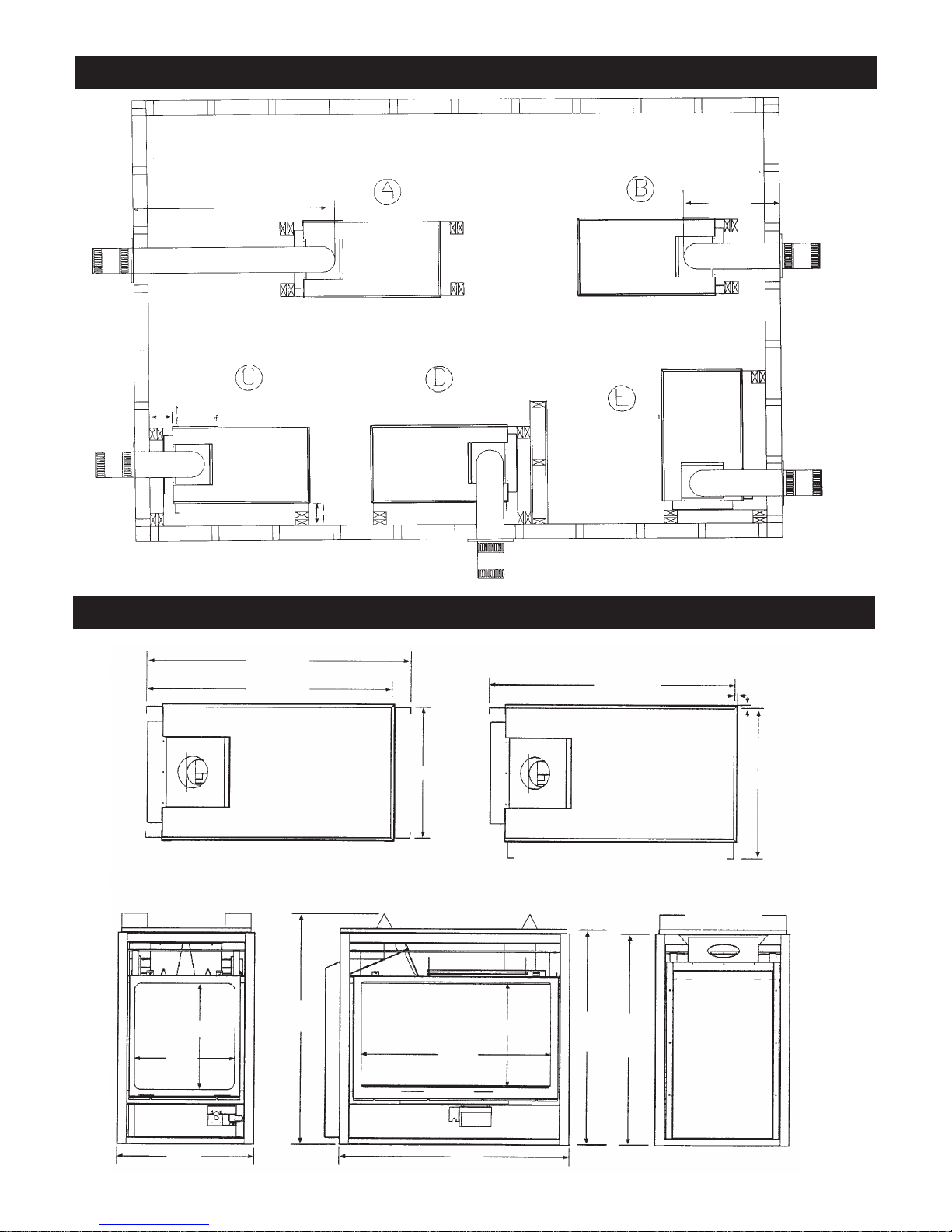
SEE - THRU UNIT
41.062"
PENINSULA UNIT
38.062"
TOP VIEW
20.687"
TOP VIEW
23.687"
.50"
.50"
CORNER UNIT R/H
38.062"
REAR
VIEW
16.125"
36.125"
16.125"
21.687"
15.50"
36.062"
29.75"
SIDE VIEW
END
VIEW
Unit Dimensions - With Louvers
31.875”
32.625”
TOP VIEW
PENINSULA
RIGHT CORNER
TOP VIEW
SEE THRU TOP
VIEW
20'-0"
6.0"
MIN.
MIN.
6.0"
ALL UNITS CAN BE VENTED VERTICAL
MAX. Horizontal Run
With Required Vertical Run
LEFT
CORNERTOP
VIEW
LEFT CORNER TOP
VIEW
MAX.
36.0"
Horizontal Run
With Min. Vertical
Run
RIGHT BURNER SYSTEM
LEFT BURNER SYSTEM
LEFT BURNER
SYSTEM
LEFT BURNER SYSTEM
RIGHT BURNER SYSTEM
RIGHT BURNER SYSTEM
LEFT BURNER SYSTEM
Locating your Appliance
6
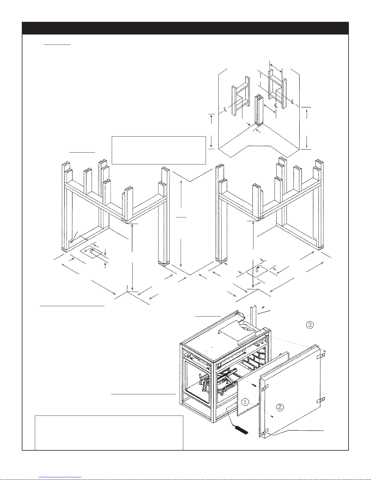
FRAMING
Using 2x4s frame to local building codes.
DO NOT install against a Vapour Barrier or Exposed
Insulation.
Framing measurements ha v e been adjusted to
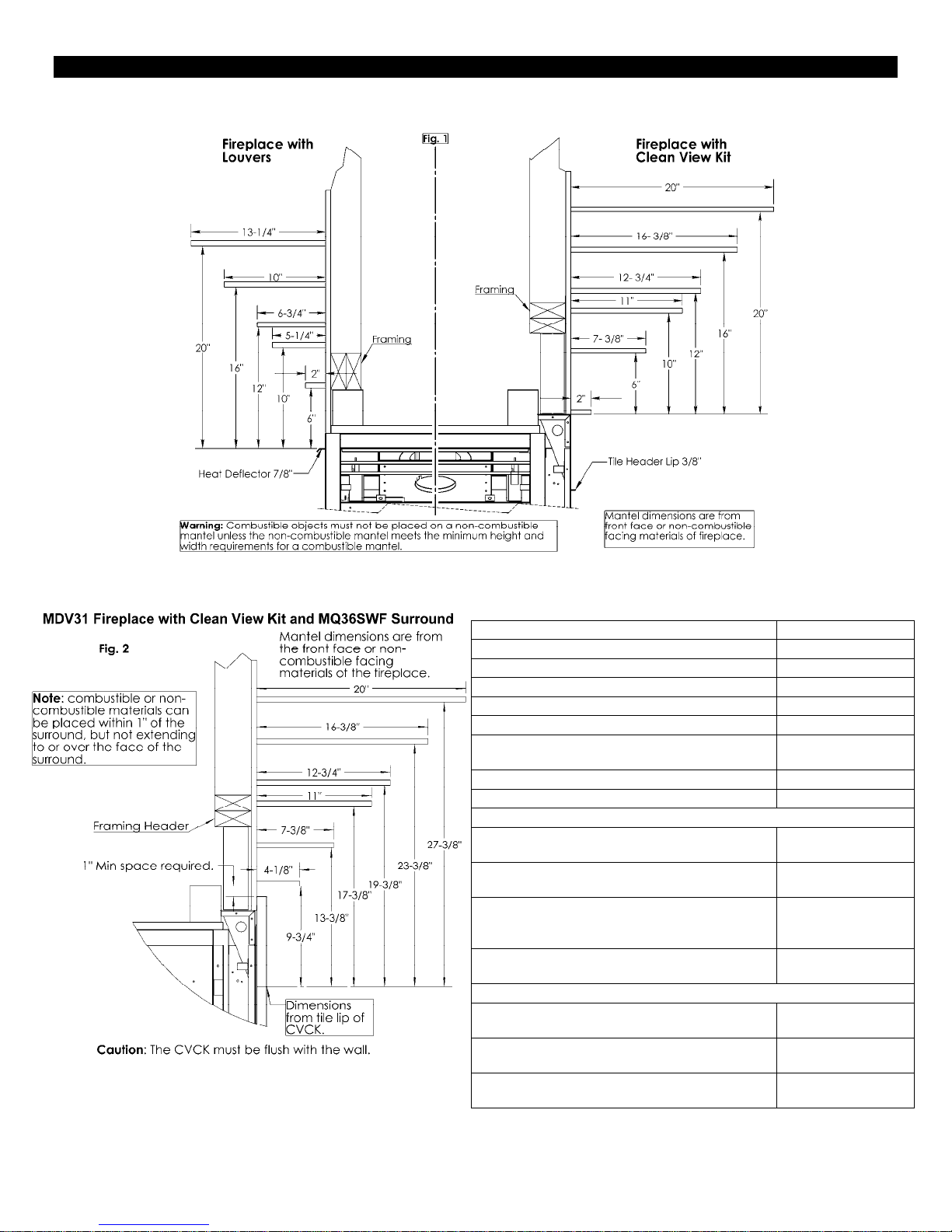
accommodate a 1/2" thick finished wall. FIGURE 1
Combustible materials may be installed flush with
the top and sides of fireplace.
It is not necessary to install a hearth with this
fireplace system. Objects placed in front of the
fireplace should be kept a minimum of 24" away from
the front face.
Fireplace bottom supplies you with two 6"x8"
holes. The use of these holes depends on valv e
and Fireplace location on riser or upper floor.
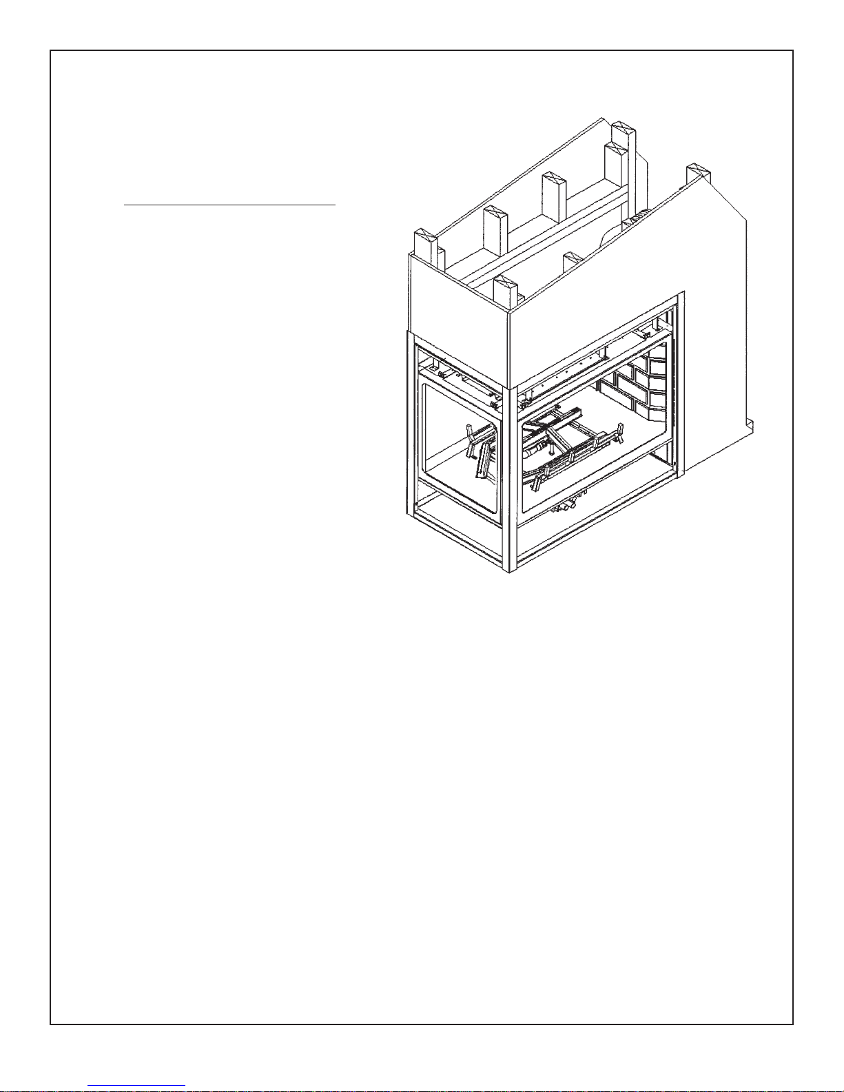
FIREPLACE ASSEMBLY
FRAMING DETAIL
THROUGH Combustible W ALL
11.0"
11.0"
MIN.
6.5"
MIN.
39.0"
MIN.
36.0"
SIDE FLUE
APPLICATION
REAR FLUE
APPLICATION
3.5" TYP.
L/H Framing
Instructions
R/H Framing
Instructions
GAS LINE
R/H UNIT
BOTTOM
ENTRY
2.0" x 3.0"
Notch for
End gas
line entry
37.0"
37.0"
14.5"
6.0"
8.0"
2.5"
7.0"
23.75"
38.125"
4.188"
27.25"
27.25"
38.125"
25.875"
23.75"
42.0"
For Combustible
Enclosure T op.
FIGURE 1
FIGURE 2
REAR STAND OFF
COMPLETE WITH
NAILING T ABS
HEAT
SHIELD
COMPLETE
WITH
NAILING
TABS
DOOR
COVER
HIGH HEAT
SILICONE
NAILING T ABS
Framing Corner L/H & R/H Installation Instructions - Louvered Unit Only
NOTE: The standoffs are non load bearing.
When installing a cabinet, a maximum weight
of 250 lbs can be installed on the 1/2” drywall
lip (located around the perimeter of the appliance).
7
1. Mount Door Cover Figure #2. First apply a
small bead of High Heat Silicone to door seal.
Mount Door and screw into place, making sure that
Door is properly sealed.
2. Hang Heat Shield on top edge of fireplace,
and secure with self tapping screws. Heat
Shield must be centered allowing a 1/2"
clearance both sides of Fireplace for
finishing material.
3. The heat shield and rear
standoff are equipped with
nailing tabs. Le v el Fireplace and
nail or screw into place.
NOTE.
R/H FIREPLACE SHOWN
For Low Profile Enclosure Ref er
to Low Profile Enclosure Section.
NOTE: Clearance to back of unit and/or sides of unit
framed into walls require 6” minim um clearance to com-
bustibles. We recommend using two (2 x 4) studs placed
against the wall as per framing diagrams. See
Locating your Appliance for additional inf ormation.
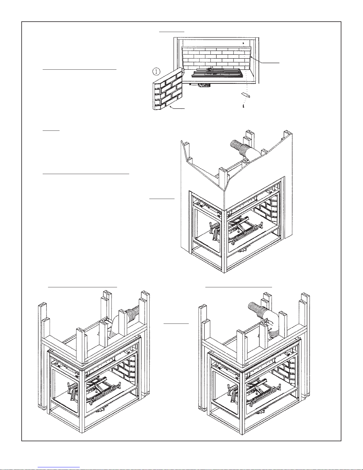
FIGURE 3
BRICK PANEL INST ALLATION
FIGURE 5
8
1. Insert side Brick panel into place,
using Brick retaining clip position and
screw to top of firebox.
2. Install rear Brick panel, brick
retaining clip located at top.
SIDE BRICK
PANEL
BRICK
CLIP
REAR BRICK
PANEL
NOTE!
For Log, Crushed Rock and Glowing
Ember installation refer to Log Placement Section.
F A CING MATERIAL INSTALLA TION
Facing material. Example DR YWALL
may be installed flush with top of
Fireplace.
Side facing to be installed to
FIGURE 4
standoffs only.
REAR FLUE INSTALLA TION
NOTE!
This UNIT is not
Load Bearing.
NOTE!
This UNIT is not
Load Bearing.
DRYWALL
SIDE FLUE INSTALLA TION
NOTE!
This UNIT is not
Load Bearing.
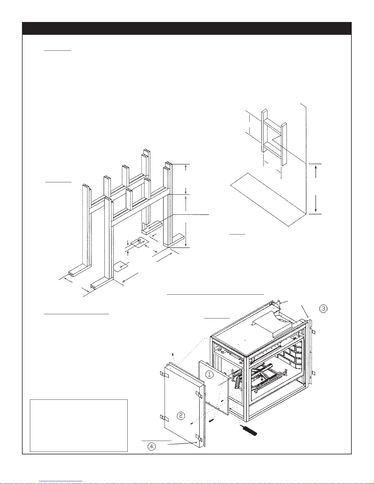
FRAMING
Framing See-Thru Installation Instructions - Louvered Unit Only
9
Using 2x4s frame to local building codes.
DO NOT install against a Vapour Barrier or Exposed
Insulation.
Framing measurements ha v e been adjusted to
accommodate a 1/2" thick finished wall. FIGURE 1
Combustible materials may be installed flush with top
of standoffs and sides of fireplace.
It is not necessary to install a hearth with this
fireplace system. Objects placed in front of the fireplace
should be kept a minimum of 24" away from the front face .
Gas line installation should be performed only after
Fireplace installation. Fireplace bottom supplies y ou with
two 6"x8" rectangular holes. The use of these holes
depends on valve and Fireplace location on riser or
upper floor.
FRAMING DETAIL
HORIZONTAL RUN
WITH MIN. VERTICAL RUN
11.0"
NOTE!
This UNIT is not
Load Bearing
FIGURE 1
GAS LINE
R/H UNIT
20.625"
BOTTOM
ENTRY
2.5"
11.062"
GAS LINE
L/H UNIT
41.125"
6.0"
FIREPLACE ASSEMBLY
1. Mount Door Cover Figure #2. First apply a
small bead of High Heat Silicone to door seal.
Mount Door and screw into place, making sure that
Door is properly sealed.
2. Hang Heat Shield on top edge of Fireplace,
and secure with self tapping screws. Heat
Shield must be centered allowing a 1/2"
clearance both sides of Fireplace for
finishing material.
3. The heat shield and rear
standoff are equipped with
nailing tabs. Le v el Fireplace and
nail or screw into place.
NOTE: Clearance to back of unit
and/or sides of unit framed into walls
require 6” minimum clearance to
combustibles. We recommend
using two (2 x 4) studs placed
against the wall as per framing diagrams. See - Locating your
NAILING T ABS
Appliance, for additional inf ormation.
THROUGH
COMBUSTIBLE
WALL
5.0" MIN.
For Combustible
Enclosure T op
2.0" X 3.0"
NOTCH FOR
END GAS
ENTRY
37.0"
NOTE
For Low Profile Enclosure Ref er
to Low Profile Enclosure Section.
.
SEE-THROUGH FIREPLACE SHO WN
FIGURE 2
HEAT
SHIELD
COMPLETE
WITH
NAILING
TABS
DOOR
COVER
HIGH TEMP
SILICONE
11.0"
MIN.
36.0"
REAR STAND OFFS
COMPLETE WITH
NAILING T ABS

F A CING MATERIAL INSTALLA TION
Facing material. Example DR YWALL
may be installed Flush with top of
Fireplace.
Side facing to be installed to
standoffs only.
NOTE!
This UNIT is not
Load Bearing
Gyprock
Gyprock
DRYW ALL
10
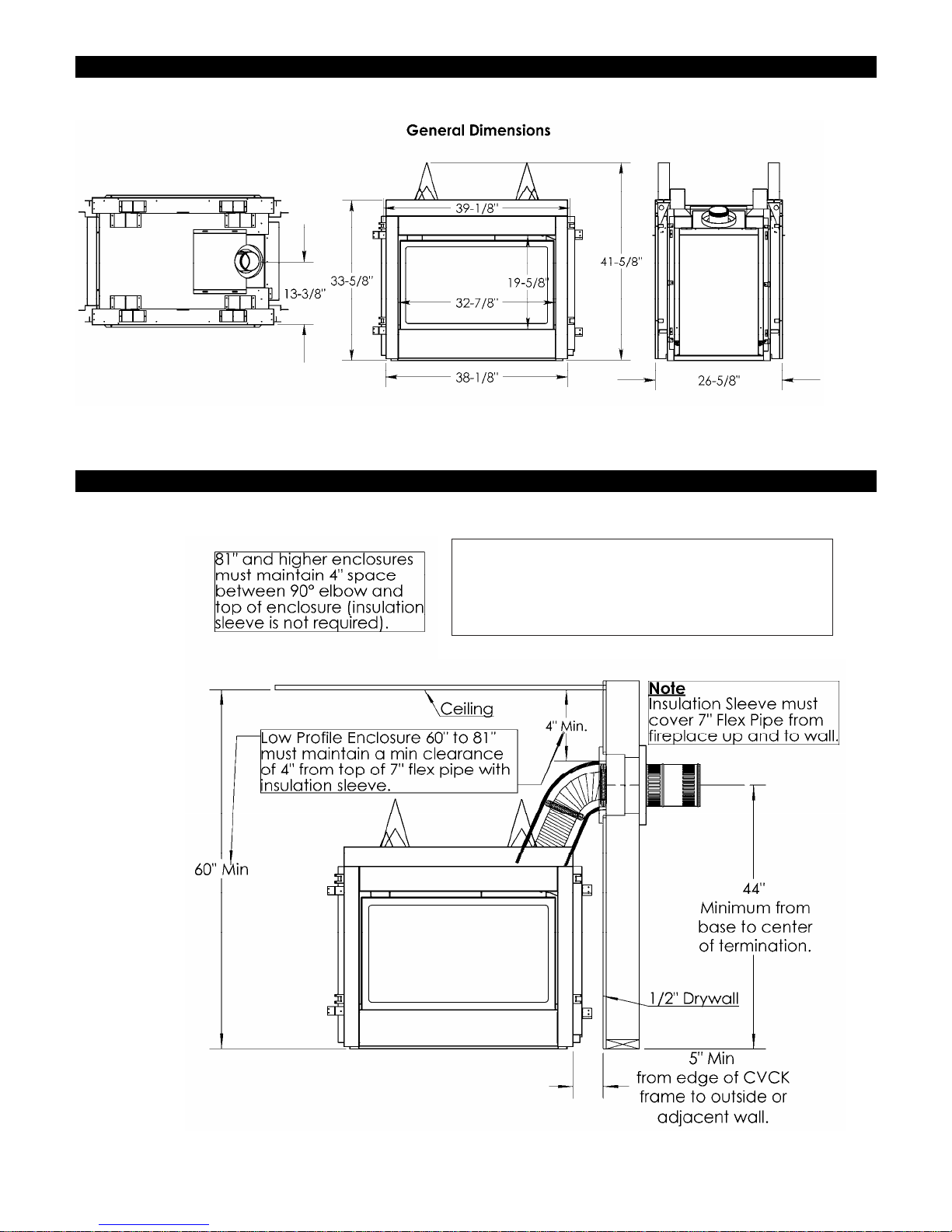
See Through With CVCK -Dimensions-
For Propane Horizontal Installations the venting
must be a minimum of one foot vertical off the flue
before the elbow on any horizontal runs of one foot
or greater. This allows for cleaner combustion and
greatly reduces carboning and cleaning of glass.
Does not apply to Back Flue models).
11
Note: When CVCK is used, a CVCK Kit must be installed on Both sides of the unit.
See Through With CVCK -Enclosures-
-See-Through With CVCK Installation-
12
Framing
(The following method assumes that framing is in place before the unit is installed.)
Using 2x4’s, frame to local building codes. DO NOT install against a Vapor Barrier or Exposed Insulation.
Framing measurements have been adjusted to accommodate a ½” thick finished wall. Combustible materials may be installe d flush with
the top and sides of the installed CVCK Kits.( “Framing and Facing Requirements” Section.)
It is not necessary to install a hearth with this fireplace system. Objects placed in front of the fireplace should be kept a minimum of 24”
away from the front face.
Gas line installation should be performed only after fireplace installation. Fireplace bottom supplies you with two 6” x 8” rectangular
holes. The use of these holes depends on valve and fireplace location on riser or upper floor.
For Low Profile Enclosure Refer to
“See Through With CVCK -Enclosures-“
Fireplace Assembly
1. Mount Door Cover. First apply a bead of High Heat Silicone to door seal. Mount Door Cover and screw into place, making
sure that door is properly sealed.
2. Hang Heat Shield on top edge of fireplace; secure with self-tapping screws. Heat Shield must be centered, allowing a
½” clearance both sides of fireplace.
3. Top Door Shield should be installed on both sides of unit when the doors are installed.
4. Place unit inside framing and center. You are now ready to install CVCK Kits onto unit (See “How to Install Clean Vie w
Kit” section).Gas line and electrical connections (blower fan, etc.) should be performed at this time.
5. Once the unit (with CVCK Kits) is installed into Framing, Facing Material may be installed (See “Framing and Facing
Requirements” Section)
.
See “Locating Your Appliance” Section for additional information.
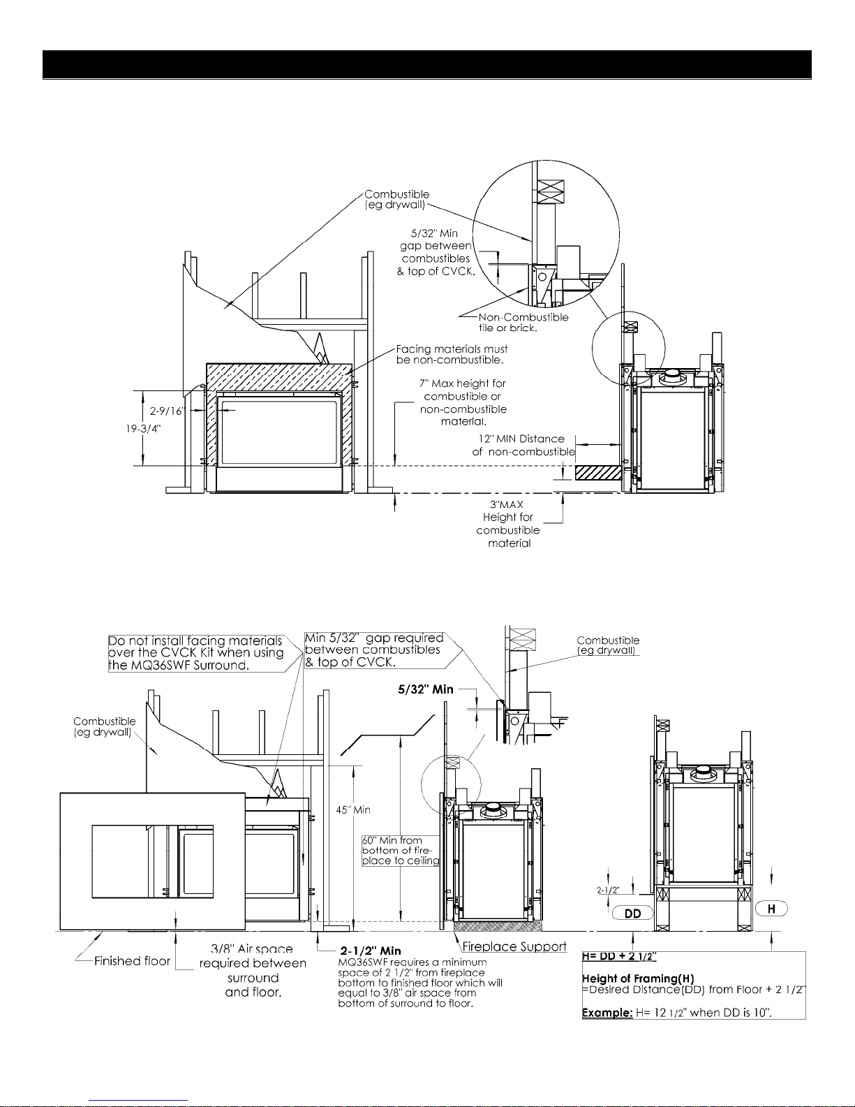
Framing and Facing Requirements
13
See Through with CVCK (Clean View Circulating Kit)
Note: When CVCK is used, a CVCK Kit must be installed on Both sides of the unit.
MDV31 with MQ36SWF Surround
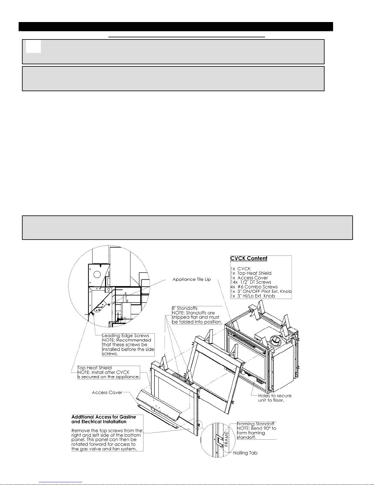
MDV31 – How to Install Clean View Kit (Z36CVCK)
14
Caution: When using CVCK do not install Louver Assembly.
WARNING: Failure to position the parts in accordance with these diagrams or failure to use only parts
specifically approved with this appliance may result in property damage or personal injury.
NOTE: When using the Clean View Kit (CVCK) and installing optional electrical components (i.e. Remote
Controls, variable speed control, and or fan modules) locate them in the Clean View access area, unless
other shielding devices like our IPI Component box is used.
1. Install optional Fan Kit (See Fan instructions).
Fold the tall 8” standoffs up into position and mount them with the supplied screws.
2.
3. Bend the center tab on the four [4] Nailing Tabs 90° as
shown below. These tabs are the standoffs for the side
Framing.
4. Place CVCK inside Fireplace door opening and, using the four [4] supplied #6 screws, fasten the CVCK to the inside
posts of the appliance.
5. Using ten [10] DT screws, install the Top Heat Shield to the upper inside portion of the CVCK. A side cut-view is
provided to illustrate how the shield is installed. It is recommended that the Leading Edge Screws be installed before
the side screws.
6. Position the appliance inside the Framing and secure it using the nailing tabs on the CVCK. Ensure that the Framing
does not exceed the standoffs bent in Step 2. Furthermore, it is recommended that the fireplace be fastened to the
floor with 4 screws as well.
7. The CVCK Kit is supplied with two [2] valve extension knobs. Align the notches and slide the extensions onto the
valve knobs.
8. DO NOT brick or tile beyond the inside area of the CVCK Kit to allow for removal of the door and ventilation.
NOTE: ADDITIONAL ACCESS FOR GASLINE INSTALLATION AND FAN ELECTRICAL INSTALLATION! When CVCK is installed
in framing, remove the four [4] screws from the bottom panel. Once screws are removed, bottom panel can be removed to access
gas valve and fan system.
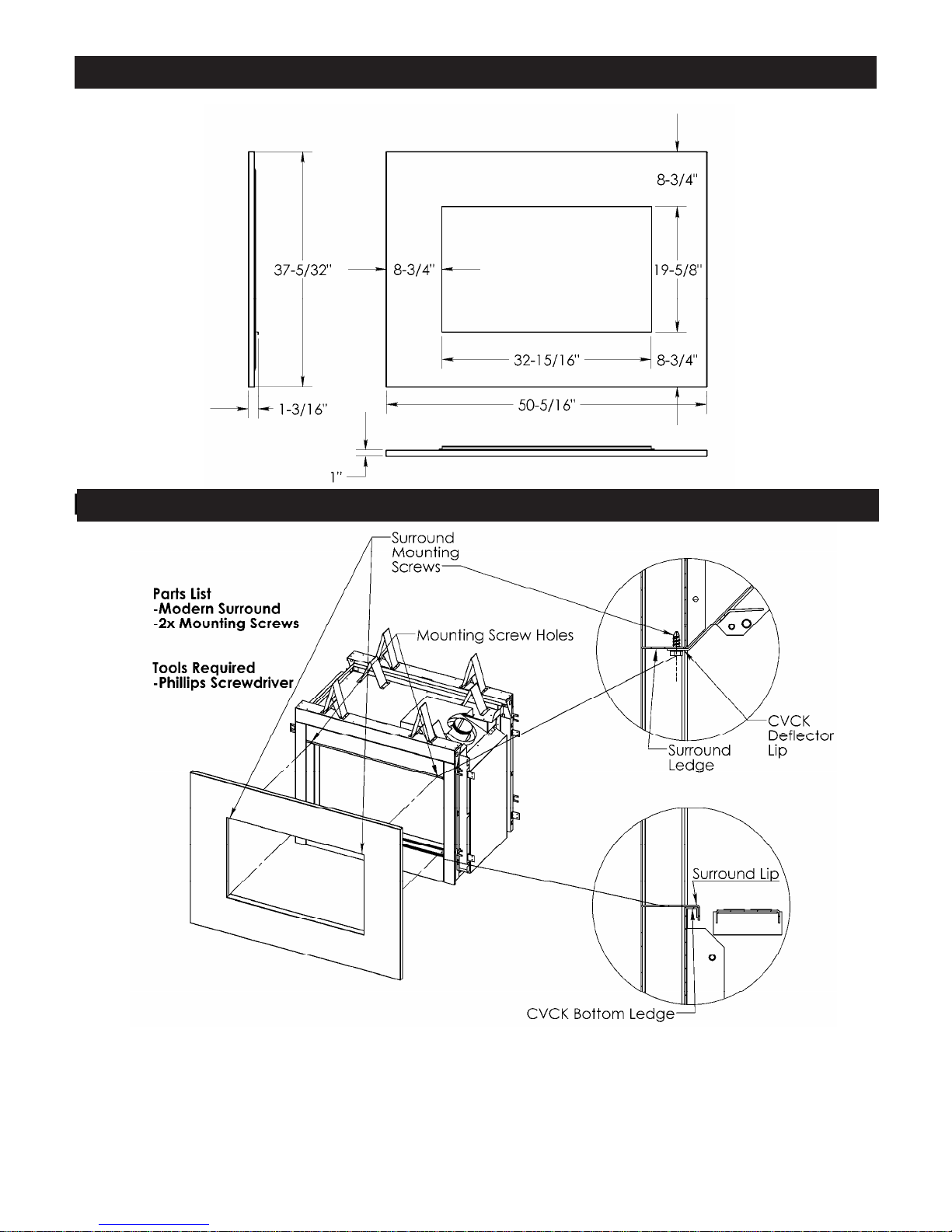
MQSW Wall Mount Surround Dimensions
MQSW Wall Mount Surround Dimensions
Installation of MQ Wall Mount Surrounds
15
Installation of Wall Mount Surrounds
1. Set Surround Lip on CVCK Ledge and ensure that it is securely in place.
2. Swing the upper portion of the Surround so that the Surround Ledge is resting on top of the CVCK Deflector Lip.
3. Align the Mounting Screw Holes and fasten the Surround in place with the supplied screws.
4. Attach optional Decorative Bands as desired.
5. To remove, simply reverse these steps.
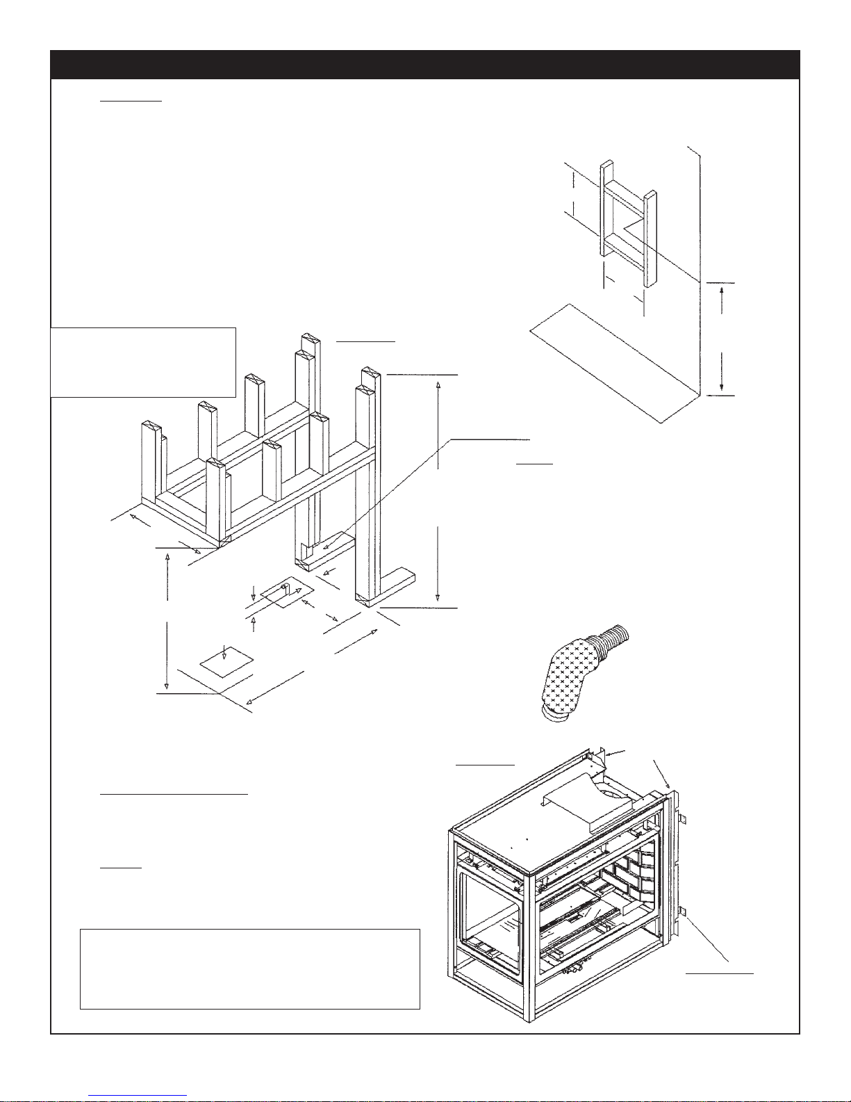
Framing Peninsula Installation Instructions - Louvered Unit Only
16
FRAMING
Using 2x4s frame to local building codes.
DO NOT install against a Vapour Barrier or Exposed
Insulation.
Framing measurements ha v e been adjusted to
accommodate a 1/2" thick finished wall. FIGURE 1
Combustible materials may be installed flush with top
and sides of fireplace.
It is not necessary to install a hearth with this
fireplace system. Objects placed in front of the fireplace
should be kept a minimum of 24" away from the front face .
Gas line installation should be performed only after
Fireplace installation. Fireplace bottom supplies y ou with
two 6"x8" rectangular holes. The use of these holes
depends on valve and Fireplace location on riser or upper
floor.
NOTE: The standoffs are non load
bearing. When installing a cabinet, a
maximum weight of 250 lbs can be
installed on the 1/2” drywall lip (located
around the perimeter of the appliance).
20.625"
37.0"
2.5"
GAS LINE
L/H UNIT
GAS LINE
R/H UNIT
BOTTOM
ENTRY
6.0"
11.062"
FIGURE 1
2.0" X 3.0"
NOTCH FOR
END GAS
LINE ENTRY
42.0" MIN.
For Combustible
Enclosure T op
FRAMING DETAIL
HORIZONTAL RUN
WITH MIN. VERTICAL RUN
11.0"
THROUGH
COMBUSTIBLE
WALL
11.0"
MIN.
36.0"
NOTE
Low profile enclosure 42.0" to 52.0"
must maintain a minimum clearance of
2" from top of 7.0" flex pipe and
insulation sleeve to bottom of comb ustib le
enclosure top. Insulation sleev e
must be installed so that it covers 7.0"
flex pipe from fireplace up and to wall
sleeve .
Refer to Low Profile Enclosure Section
for additional information.
38.125"
FIREPLACE ASSEMBLY
Rear standoffs are equipped with
nailing tabs. Le v el Fireplace nail or scre w
into place.
NOTE!
For Log, Crushed Rock and Glowing Ember
installation refer to Log Placement Section.
NOTE: Clearance to back of unit and/or sides of unit
framed into walls require 6” minimum clearance to combustibles. We recommend using two (2 x 4) studs placed
against the wall as per framing diagrams. See
Locating your Appliance, for additional information.
INSULATION
SLEEVE
REAR STAND OFFS
COMPLETE WITH
NAILING T ABS
FIGURE 2
NAILING T ABS
F A CING MATERIAL INSTALLA TION
Facing material. Example DR YWALL
may be installed Flush with top of
Fireplace.
Side facing to be installed to
standoffs only.
DRYW ALL
17

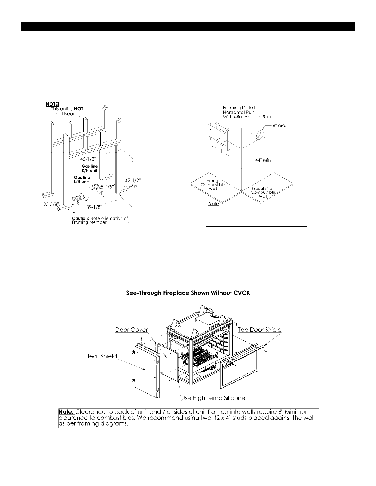
Low Profile Enclosures - Louvered Unit Only
18
NOTE
INSULATION SLEEVE MUST
COVER 7.0" FLEX PIPE FROM
FIREPLACE UP AND TO WALL.
SLEEVE FOR LOW PROFILE
ENCLOSURES MAXIMUM 34.0".
LOW PROFILE ENCLOSURE
42.0" TO 52.0" MUST MAINTAIN
A MINIMUM CLEARANCE OF
2.0" FROM TOP OF 7.0" FLEX
PIPE AND INSULATION SLEEVE.
52.0" AND HIGHER ENCLOSURE
MUST MAINTAIN 4.0" ABOVE 7.0"
FLEX PIPE WITHOUT INSULATION
SLEEVE.
NOTE: Clearance to back of unit and/or sides of unit
framed into walls require 6” minimum clearance to combustibles. We recommend using two (2 x 4) studs placed
against the wall as per framing diagrams. See Locating your Appliance, for additional information.
NOTE
WITH USING DURA-VENT
PIPE AND ADAPTER MINIMUM
HEIGHT OF 52.0" MUST BE
MAINTAINED FOR PROPER
CLEARANCES. INSULATION
SLEEVE IS NOT REQUIRED.
THIS WILL LEAVE A 4.0"
MINIMUM CLEARANCE TO
COMBUSTIBLE TOP.
For Propane Horizontal Installations the venting
must be a minimum of one foot vertical off the flue
before the elbow on any horizontal runs of one foot
or greater. This allows for cleaner combustion and
greatly reduces carboning and cleaning of glass.
Does not apply to Back Flue models).
52.0"
52.0" REQUIRES INSULATION SLEEVE
MIN. LOW PROFILE
ENCLOSURES REQUIRES
INSULATION SLEEVE
34.0"
2.0"
42.0"
36.0"
MINIMUM FROM
BASE TO
CENTER OF
TERMINATION
1/2" Gyprock
Clearances – MDV31 – Mantels & Surrounds
19
Clearance to Combustibles
Back (of unit) 6 inches /152mm
Sides (of unit in framing) 6 inches /152mm
Vertical Pipe 1 inch /25mm
Back (from standoffs) 0 inches /0mm
Side (from standoffs) 0 inches /0mm
Floor 0 inches /0mm
Ceiling (from bottom of fireplace) 60 inches
Top of Horizontal Pipe 2.5 inches / 64mm
Top Framing from Standoff 0 inches /0mm
Louvered Units Only
Top of 90° Bend No Sleeve, in Enclosure over
52”
Bottom of Top Enclosure with Insulation
Sleeve
In Low Profile Enclosures from 42” to 52”
Top of Horizontal Pipe in Enclosure without
Sleeve
Top of Horizontal Pipe in Low Profile
Enclosure with Insulation Sleeve
MDV31 With Clean View Kit
Top of 90° Bend No Sleeve, in enclosure over
81”
Bottom of Top Enclosure with Insulation
Sleeve
Top of Horizontal Pipe in Enclosure with
insulation Sleeve
/152.4cm
4 inches /102mm
42 inches
/1067mm
12 inches /305mm
2 inches 51mm
4 inches /102mm
60 inches
/152.4cm
4 inches /102cm
 Loading...