

Kingsman IVF36 Operation And Installation Manual
1
UNVENTED (VENT-FREE)
Zero Clearance Fireplace
(Insert option)
Certified to: ANSI Z21.11.2b – 2004, Z21.11.2 – 2002, Z21.11.2a - 2003
MODEL NUMBER IVF36
Owner’s Operation
and Installation Manual
Stock Numbers: IVF36MVN, IVF36MVP Circulating Models
Warning
If the information in this manual is not followed
exactly, a fire or explosion my result causing property damage,
personal injury, or loss of life.
– Do not store or use gasoline or other flammable vapors and liquids in
the vicinity of this or any other appliance.
– WHAT TO DO IF YOU SMELL GAS
• Do not try to light any appliance.
• Do not touch any electrical switch; do not use any phone in your
building.
• Immediately call your gas supplier from a neighbor’s phone. Follow
the gas supplier’s instructions.
• If you cannot reach your gas supplier, call the fire department.
– Installation and service must be performed by a qualified installer,
service agency, or the gas supplier.
Warning
Improper installation, adjustment,
alteration, service, or maintenance
can cause injury or property
damage. Refer to this manual for
correct installation and operational
procedures. For assistance or
additional information consult a
qualified installer, service agency, or
the gas supplier.
Save this manual for future reference • 2340 Logan Ave., Winnipeg, MB, Canada, Phone: (204) 632-1962 • Printed in Canada • PART 36IVF-MAN
Rev. 30/03/06
Warning
Carefully review the instructions
supplied with the decorative type
unvented room heater for the
minimum size requirement.
DO NOT INSTALL THE APPLIANCE
IN THIS FIREBOX UNLESS THIS
FIREBOX MEETS THE MINIMUM
DIMENSIONS REQUIRED FOR THE
INSTALLATION
Warning
FOR USE ONLY WITH
DECORATIVE TYPE UNVENTED
ROOM HEATERS
DO NOT BUILD A WOOD FIRE.
Warning
This is an unvented gas-fired heater. It uses air (oxygen) from the
room in which installed. Provisions for adequate combustion and
ventilation must be provided. Refer to Page 7.
This appliance must be
installed by a licensed
plumber or gas fitter in
the Commonwealth of
Massachusetts and meet
the requirements of 527
CMR 30 and 248 CMR.

2

3
TABLE OF CONTENTS
SECTION PAGE
FIreplace Accessories & Parts List . . . . . . . . . . . . . . . . . . . . . . . . . . . . . . . . . . . . . . . . . . . . . . . . . . . . . . . . . . . . . . . . . . . . . . . .4
Safety Information . . . . . . . . . . . . . . . . . . . . . . . . . . . . . . . . . . . . . . . . . . . . . . . . . . . . . . . . . . . . . . . . . . . . . . . . . . . . . . . . . . . .5
Local Codes . . . . . . . . . . . . . . . . . . . . . . . . . . . . . . . . . . . . . . . . . . . . . . . . . . . . . . . . . . . . . . . . . . . . . . . . . . . . . . . . . . . . .6
For Your Safety Read Before Lighting . . . . . . . . . . . . . . . . . . . . . . . . . . . . . . . . . . . . . . . . . . . . . . . . . . . . . . . . . . . . . . . .6
Air for Combustion and Ventilation . . . . . . . . . . . . . . . . . . . . . . . . . . . . . . . . . . . . . . . . . . . . . . . . . . . . . . . . . . . . . . . . . . . . . . .7
Providing Adequate Ventilation . . . . . . . . . . . . . . . . . . . . . . . . . . . . . . . . . . . . . . . . . . . . . . . . . . . . . . . . . . . . . . . . . . . . . .7
Determining Air Flow for Firebox Location . . . . . . . . . . . . . . . . . . . . . . . . . . . . . . . . . . . . . . . . . . . . . . . . . . . . . . . . . . . .7
Ventilation Air From Inside Building . . . . . . . . . . . . . . . . . . . . . . . . . . . . . . . . . . . . . . . . . . . . . . . . . . . . . . . . . . . . . . . . .9
Ventilation Air From Outdoors . . . . . . . . . . . . . . . . . . . . . . . . . . . . . . . . . . . . . . . . . . . . . . . . . . . . . . . . . . . . . . . . . . . . .10
Installing . . . . . . . . . . . . . . . . . . . . . . . . . . . . . . . . . . . . . . . . . . . . . . . . . . . . . . . . . . . . . . . . . . . . . . . . . . . . . . . . . . . . . . . . . . 11
Installation Clearances . . . . . . . . . . . . . . . . . . . . . . . . . . . . . . . . . . . . . . . . . . . . . . . . . . . . . . . . . . . . . . . . . . . . . . . . . . . .11
IVF36 insert dimensions . . . . . . . . . . . . . . . . . . . . . . . . . . . . . . . . . . . . . . . . . . . . . . . . . . . . . . . . . . . . . . . . . . . . . . . . . 12
Framing dimensions for zero clearance . . . . . . . . . . . . . . . . . . . . . . . . . . . . . . . . . . . . . . . . . . . . . . . . . . . . . . . . . . . . . . 13
Installing by Framing Fireplace . . . . . . . . . . . . . . . . . . . . . . . . . . . . . . . . . . . . . . . . . . . . . . . . . . . . . . . . . . . . . . . . . . . . 14
Installing Firebox Using Optional Pre-Built Mantel Cabinets . . . . . . . . . . . . . . . . . . . . . . . . . . . . . . . . . . . . . . . . . . . . 15
Installing Gas Line . . . . . . . . . . . . . . . . . . . . . . . . . . . . . . . . . . . . . . . . . . . . . . . . . . . . . . . . . . . . . . . . . . . . . . . . . . . . . . 17
Installing Burner Systems into Firebox . . . . . . . . . . . . . . . . . . . . . . . . . . . . . . . . . . . . . . . . . . . . . . . . . . . . . . . . . . . . . . 17
Millivolt Lighting Instructions . . . . . . . . . . . . . . . . . . . . . . . . . . . . . . . . . . . . . . . . . . . . . . . . . . . . . . . . . . . . . . . . . . . . .19
Cleaning and Servicing of Burner / ODS Pilot . . . . . . . . . . . . . . . . . . . . . . . . . . . . . . . . . . . . . . . . . . . . . . . . . . . . . . . . 20
Log Placement . . . . . . . . . . . . . . . . . . . . . . . . . . . . . . . . . . . . . . . . . . . . . . . . . . . . . . . . . . . . . . . . . . . . . . . . . . . . . . .21-22
Options, Brass trim and overlays . . . . . . . . . . . . . . . . . . . . . . . . . . . . . . . . . . . . . . . . . . . . . . . . . . . . . . . . . . . . . . . . . . .23
Insert surround installation . . . . . . . . . . . . . . . . . . . . . . . . . . . . . . . . . . . . . . . . . . . . . . . . . . . . . . . . . . . . . . . . . . . . . . . .24
Fan Kit servicing and replacement . . . . . . . . . . . . . . . . . . . . . . . . . . . . . . . . . . . . . . . . . . . . . . . . . . . . . . . . . . . . . . . . . .25
Illustrated Parts Lists . . . . . . . . . . . . . . . . . . . . . . . . . . . . . . . . . . . . . . . . . . . . . . . . . . . . . . . . . . . . . . . . . . . . . . . . . . . . . . . . .26
Troubleshooting . . . . . . . . . . . . . . . . . . . . . . . . . . . . . . . . . . . . . . . . . . . . . . . . . . . . . . . . . . . . . . . . . . . . . . . . . . . . . . . . . . 27-28
Warranty . . . . . . . . . . . . . . . . . . . . . . . . . . . . . . . . . . . . . . . . . . . . . . . . . . . . . . . . . . . . . . . . . . . . . . . . . . . . . . . . . . . . . . . . . . 29

4
FIREPLACE ACCESSORIES AND PARTS LIST
Product No. Description
IVF36 VENT FREE INSERT AND ZERO CLEARANCE FIREBOX
Listed for USA as a Vent Free Firebox, Includes Dual Burner, Variable Speed
Controlled Blower with Heat Sensor, Millivolt Valve, ODS Pilot, Pull Screens
(Minimum Size of Fireplace for installation 28 3/4”W x 24 1/4”H x 13 3/4”D)
IVF36MVN Vent Free Insert - Natural Gas (as above) 32,000 BTU/HR
IVF36MVP Vent Free Insert - Liquid Propane (as above) 33,000 BTU/HR
LOG SET: (Required For Each Unit)
LOGF18 Log Set - Fibre split Oak 18”
LOGF24 Log Set - Fibre split Oak 24”
GRILL KIT: (Required For Each Unit)
I36GBA Grill Kit - Classic Builder Antique Brass
I36GBC Grill Kit - Classic Builder Chrome
I36GBP Grill Kit - Classic Builder Polish Brass
I36GBL Grill Kit - Black
I36GAB Grill Kit - Antique Brass
I36GPB Grill Kit - Polish Brass
I36GCR Grill Kit - Chrome
CHOOSE ONE SURROUND AND TRIM IF AVAILABLE: (If needed)
I36S2939B Surround Soft Arch - Black (1 piece)
(Coverage Size 29 1/2”H x 39”W)
I36S3147B Surround Medium - Black
I36T3147A Trim Kit - Antique Brass
I36T3147C Trim Kit - Chrome
I36T3147P Trim Kit - Polish Brass
I36T3147B Trim Kit - Black
(Size 31”H x 47”W)
I36S3647B Surround Large - Black
I36T3647A Trim Kit - Antique Brass
I36T3647C Trim Kit - Chrome
I36T3647P Trim Kit - Polish Brass
I36T3147B Trim Kit - Black
(Size 36”H x 47”W)
ACCESSORIES OPTIONS:
I36DTAB Door Trim Kit - Antique Brass
I36DTCR Door Trim Kit - Chrome
I36DTPB Door Trim Kit - Polish Brass
Z1ADBL Arch Door Frame - Black
Z36ADDX Arch Door Frame - Deluxe Black (352)
Z36ADDA Arch Door Frame - Double Arch Black (354)
Z36ADDD Arch Door Frame - Double Door Arch Black (355)
Z1ADAB Arch Door Frame - Antique Brass
Z36ADCR Arch Door Frame - Chrome
Z1ADPB Arch Door Frame - Polish Brass
ZVF36DS Door Frame - c/w Fixed Screen
Z1MT Thermostat Millivolt Wall Mount
Z80PT Thermostat Programmable Digital Millivolt Wall Mount (IF80-40)
Z1RC Remote Control Millivolt (On/Off with LED) (Model 1)
ZART Remote Control Thermostat Millivolt (Model K)
RMCBN Remote Control - Basic - Natural Gas (On/Off, Hi/Lo Flame Adjustment)
RMCBP Remote Control - Basic - Liquid Propane (On/Off, Hi/Lo Flame Adjustment)
DCHS Remote Control Heatshield
Z36RL Refractory Liner (3 piece)
5
SAFETY INFORMATION WARNINGS
WARNINGS
Important: Read this owner’s manual carefully and completely before trying to assemble, operate, or service this firebox.
Improper use of this firebox can cause serious injury or
death from burns, fire, explosion, electrical shock, and
carbon monoxide poisoning.
Early signs of carbon monoxide poisoning resemble the
flu, with headaches, dizziness, and / or nausea. If you have
these signs, the heater may not be working properly. Get
fresh air at once! Turn off gas appliance. Have appliance
serviced. Some people (such as pregnant women, persons
with heart or lung disease, persons with anemia and those at
high altitudes) are more affected by carbon monoxide than
others. Make certain you read and understand all warnings.
1. Use correct gas type for your appliance. Do not convert
from one gas type to another.
2. If this appliance is for use with Propane gas, do not place propane supply tank(s) inside any structure. Locate propane
supply tank(s) outdoors.
3. If you smell gas:
– Shut off gas supply.
– Do not try to light any appliance.
– Do not touch any electrical switch; do not use any phone in your building.
– Immediately call your gas supplier from a neighbor’s phone. Follow the gas supplier’s instructions.
– If you cannot reach your gas supplier, call the fire department.
4. Do not use this appliance for burning trash or cooking. Never place matches, paper, garbage, or any other material on
top of logs or logs into flame.
5. Always operate appliance with front fireplace screens closed.
6. Make sure any safety screen or guard removed for servicing is in place before running appliance.
7. Never run appliance in a small, closed room. Open the door into next room to help ventilate.
8. If appliance shuts off, do not relight until you provide fresh outside air. If appliance keeps shutting off, have it serviced.
9. Do not run appliance:
– where flammable liquids or vapors are used or stored.
– under dusty conditions.
10. Surface of appliance becomes very hot when operating. Keep children and adults away from hot surface. Appliance will
remain hot for some time after shutdown. Allow surface to cool before touching.
11. Do not use this appliance if any part has been submerged under water. Immediately cal a qualified technician to inspect
the appliance and to replace any part of the control system and gas control which has been under water.
12. The installation must conform with local codes or, in the absence of local codes, with the National Fuel Gas Code, ANSI
Z223.1.
13. Never install the appliance:
– in a bedroom, bathroom, mobile home, or recreational vehicle.
– where curtains, furniture, clothing, or other flammable objects are less than forty-two inches (42”) from the front
of the appliance.
– in high traffic areas.
– in windy or drafty areas.
14. Disconnect the appliance and its individual shut off valve from the gas supply piping system during any pressure testing
of that system at test pressures in excess of 1/2 psig, (3.5kPa).
DANGER
CARBON MONOXIDE POISONING
MAY LEAD TO DEATH!
NOTE: It is recommended that a Carbon Monoxide (CO)
Detector be installed in or near bedrooms and on all levels
of your home. Place a detector about 15 feet (4.5 meters)
outside the room that houses your gas appliance.
6
SAFETY INFORMATION WARNINGS Cont.
15. Isolate the appliance from the gas supply piping system by closing its individual manual shut off valve during any
pressure testing of the the gas supply piping system at test pressure equal or less than 1/2 psig.
16. Do not use any type of after-market blower that fits inside the fireplace. Drafts created by these type of blowers may
cause sooting.
17. Turn off appliance and let cool before servicing. Only a qualified service person should install, service and repair
appliance.
18. Inspect the appliance before use and at least annually by a professional service person. Frequent cleaning may be
required due to excessive lint from carpeting, bedding material, etc. It is important that control compartment, burner and
circulating air passage of the appliance be kept open.
19. When operated for the first time, there will be some smell from the appliance. This will diminish and disappear after a
few hours of operation.
20. Warning: Do not allow fans to blow directly into the fireplace. Avoid any drafts that alter flame patterns.
21. Warning: Do not use a blower insert, heat exchanger insert or other accessory not approved for use with this heater.
22. The firebox canopy must not be replaced with a canopy which may be provided with the decorative type UNVENTED
room heater.
23. Warning: Do not operate ceiling fans in same room as the vent free appliance.
24. Must be installed by a licenced gasfitter in the Commonwealth of Massachusetts. Complies to code 527CMR.
25. Unvented gas fired appliances may be used only for supplemental heat and/or decorative purposes and under no
circumstances shall they provide a primary heat source.
LOCAL CODES
Install and use fireplace with care. Follow all local codes. In
the absence of local codes, use the latest edition of The
National Fuel Gas Code ANSI Z223.1, also known as NFPA
54*. Firebox must be electrically grounded in accordance
with the National Electrical Code, ANSI/NFPA 70 (latest
edition).
*Available from:
American National Standards Institute, Inc. National Fire Protection Association, Inc.
1430 Broadway Batterymarch Park
New York, NY 10018 Quincy, MA 02260
FOR YOUR SAFETY READ BEFORE LIGHTING
A. This appliance has a pilot which must be lighted by hand. When lighting the pilot, follow these instructions exactly.
B. Before lighting, smell all around the appliance area for gas. Be sure to smell next to the floor because some gas is
heavier than air and will settle on the floor.
What to do if you smell gas
• Do not try to light any appliance.
• Do not touch any electric switch; do not use any phone in your building.
• Immediately call your gas supplier from a neighbor’s phone. Follow the gas supplier’s instructions.
• If you cannot reach your gas supplier, call the fire department.
C. Use only your hand to push in or turn the gas control knob. Never use tools. If the knob will not push in or turn by hand,
don’t try to repair it, call a qualified service technician or gas supplier. Force or attempted repair may result in a fire or
explosion.
D. Do not use this appliance if any part has been under water. Immediately call a qualified service technician to inspect the
appliance and to replace any part of the control system and any gas control which has been under water.
WARNING
If you do not follow these instructions exactly, a fire or
explosion may result causing property damage, personal
injury or loss of life.

7
AIR FOR COMBUSTION AND VENTILATION
Today’s homes are built more energy efficient than ever. New materials, increased insulation, and new construction methods
help reduce heat loss in homes. Home owners weather strip and caulk around windows and doors to keep the cold air out
and the warm air in. During heating months, home owners want their homes as airtight as possible.
While it is good to make your home energy
efficient, your home needs to breathe. Fresh air must enter
your home. All fuel-burning appliances need fresh air for
proper combustion and ventilation.
Exhaust fans, fireboxes, clothes dryers, and fuel burning
appliances draw air form the house to operate. You must
provide adequate fresh air for these appliances. This will
insure proper venting of vented fuel-burning appliances.
PROVIDING ADEQUATE VENTILATION
The following are excerpts from National Fuel Gas Code. NFPA 54/ANSI Z223.1, Section 5.3, Air for Combustion and
Ventilation:
All spaces in homes fall into one of the three following ventilation classifications:
1. Unusually Tight Construction; 2. Unconfined Space; 3. Confined Space.
The information on pages 8 through 10 will help you classify your space and provide adequate ventilation.
Unusually Tight Construction
The air that leaks around doors and windows may provide enough fresh air for combustion and ventilation. However, in
building of unusually tight construction, you must provide additional fresh air.
Unusually tight construction is defined as construction where:
a. walls and ceilings exposed to the outside atmosphere have a continuous water vapor retarder with a rating of one
perm (6 x 10-11 per pasec-m2) or less with openings gasketed or sealed and
b. weather stripping has been added on openable windows and doors and
c. caulking or sealants are applied to areas such as joints around window and door frames, between sole plates and
floors, between wall-ceiling joints, between wall panels, at penetrations for plumbing, electrical, and gas lines, and
at other openings.
If your home meets all of the three criteria above, you must provide additional fresh air.
See Ventilation Air From Outdoors, page 10.
Confined and Unconfined Space
The National Fuel Gas Code (ANSIZ223.1, 1992 Section 5.3) defines a confined space as a space whose volume is less than
50 cubic feet per 1,000 btu per hour (4.8 m3 per kw) of the aggregate input rating of all appliances installed in that space.
Rooms communicating directly with the space in which the appliances are installed*, through openings not furnished with
doors, are considered a part of the unconfined space.
*Adjoining rooms are communicating only if there are doorless passageways or ventilation grills between them.
DETERMINING AIR FLOW FOR FIREBOX LOCATION
Determining if You Have a Confined or Unconfined Space
Use the work sheet on the next page to determine if you have a confined or unconfined space.
Space: Includes the room in which you will install firebox plus any adjoining rooms with doorless
passageways or ventilation grills between the rooms.
WARNING
This firebox shall not be installed in a confined space
unless provisions are provided for adequate combustion
and ventilation air. Read the following instructions to
insure proper fresh air for this and other fuel-burning
appliances in your home.

8
AIR FOR COMBUSTION AND VENTILATION Cont.
1. Determine the volume of the space (length x width x height).
Length x Width x Height = ______________ cu. ft. (volume of space)
Example: Space size 22ft. (length) x 18 ft. (width)x8ft.(ceiling height) = 3168 cu. ft. (volume of space)
If additional ventilation to adjoining room is supplied with grills or openings, add the volume of these rooms to the total
volume of the space.
2. Divide the space volume by 50 cubic feet to determine the maximum Btu/Hr the space can support.
______________ (volume of space) ÷ 50 cu. ft. = 63.3 or 63,300 (maximum Btu/Hr the space can support)
3. Add the Btu/Hr of all fuel burning appliances in the space.
Vent-free firebox __________________ Btu/Hr
Gas water heater* __________________ Btu/Hr
Gas furnace __________________ Btu/Hr
Vented gas heater __________________ Btu/Hr
Gas firebox logs __________________ Btu/Hr
Other gas appliances* + __________________ Btu/Hr
Total = __________________ Btu/Hr
Example: Gas water heater 40,000 Btu/Hr
Vent-free firebox with log heater +
39,000 Btu/Hr
Total = 79,000Btu/Hr
* Do not include direct-vent gas appliances. Direct-vent draws combustion air from the outdoors and vents to the
outdoors.
4. Compare the maximum Btu/Hr the space can support with the actual amount of Btu/Hr used.
__________________ Btu/Hr (maximum the space can support)
__________________ Btu/Hr (actual amount of Btu/Hr used)
Example: 63,300 Btu/Hr (maximum the space can support)
79,000 Btu/Hr (actual amount of Btu/Hr used)
The space in the above example is a confined space because the actual Btu/Hr used is more than the maximum Btu/Hr the
space can support. You must provide additional fresh air. Your options are a follows:
A. Rework work sheet, adding the space of an adjoining room. If the extra space provides and unconfined space, remove
door to adjoining room or add ventilation grills between rooms, See Ventilation Air from Inside Building, page 9.
B. Vent room directly to the outdoors. See ventilation Air
from Outdoors, page 10.
C. Install a lower Btu/Hr firebox, if lower Btu/Hr size
makes room unconfined.
If the actual Btu/Hr used is less than the maximum Btu/Hr
the space can support, the space is an unconfined fined
space. You will need no additional fresh air ventilation.
WARNING
If the area in which the firebox and gas log heater may be
operated is smaller than that defined as an unconfined
space, provide adequate combustion and ventilation air by
one of the methods described in the National Fuel Gas
Code, ANSI Z223.1, 1992, Section 5.3.
9
AIR FOR COMBUSTION AND VENTILATION Cont.
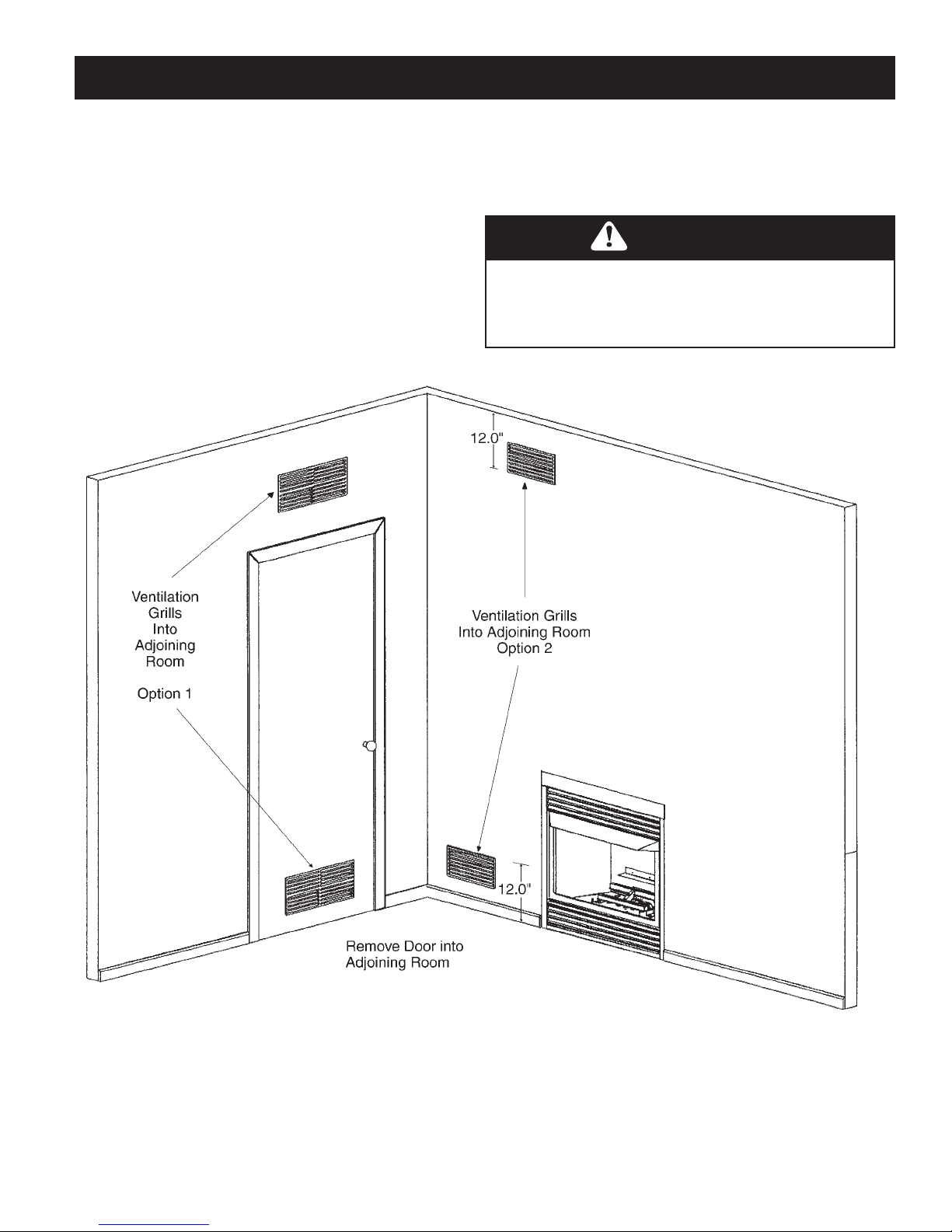
VENTILATION AIR FROM INSIDE BUILDING
This fresh air would come from an adjoining unconfined space. When ventilating to an adjoining unconfined space, you
must provide two permanent openings: one within 12” of the ceiling and one within 12” of the floor on the wall connecting
the two spaces. You can also remove door into adjoining
room. Follow the National Fuel Gas Code NFPA
54/ANSIZ223.1, Section 5.3, Air for Combustion and
Ventilation for required size of ventilation grills or ducts.
FIGURE 5 - Ventilation Air from Inside Building
WARNING
Rework worksheet, adding the space of the adjoining
unconfined space. The combined spaces must have
enough fresh air to supply all appliances in both spaces.
 Loading...