

Kingsman IDV26, IDV43, IDV33 Installation Instructions Manual
Installation Instructions
Gas Fired Direct Vent Room Heater Inserts Listed Certified for USA. and Canada
Model Numbers:
IDV26 – Stock Numbers: IDV26N, IDV26LP, IDV26NE,IDV26LPE
Minimum Fireplace Opening Required: 33”W x 19-1/2”H x 14-1/4”D Components In
28”W x 19-1/2”H x 14-1/4”D Components Out
IDV33 - Stock Numbers: IDV33N, IDV33NE, IDV33LP, IDV33LPE
Minimum Fireplace Opening Required: 26-1/4”W x 21-3/8”H x 14-3/8”D
IDV43– Stock Numbers: IDV43N, IDV43NE, IDV43LP, IDV43LPE
Minimum Fireplace Opening Required: 30-3/4”W x 25-5/8”H x 14-3/4”D
Are Certified to: ANSI Z21.88-2014 • CSA 2.33-2014
⚠WARNING: The IDV26/IDV33/IDV43 Fireplace
Insert was designed for installation in a solid fuel
fireplace that has been installed in accordance
with national, provincial/state and local building
codes and is constructed of noncombustible
materials. Do not remove any refractory materials
from any masonry solid fuel fireplace.
The IDV26/IDV33/IDV43 Fireplace Insert was
designed for installation in a zero clearance type
listed solid fuel burning factory built fireplace. It may
be necessary to remove the damper plate, refractory
liners, log grates, glass door, and screen rails/mesh.
Removal of the smoke baffle is necessary in most
cases.
A Division of R-Co. Inc.
2340 Logan Avenue
Winnipeg, Manitoba, Canada R2R 2V3
Ph: (204) 632-1962
Printed in Canada March 22, 2016
Part # 43IDV-MAN14
INSTALLER: Leave this manual with the
appliance.
CONSUMER: Retain this manual for
future reference.
This appliance may be installed in an
aftermarket, permanently located,
manufactured home (USA only) or mobile
home, where not prohibited by local codes.
This appliance is only for use with the type
of gas indicated on the rating plate. This
appliance is not convertible for use with
other gases, unless a certified kit is used.
CAPELLA

Table of Contents.....................................................................................................................................................
2-3
Pre-installation Questions and Answers..................................................................................................................
4
Operating Instructions..............................................................................................................................................
4
Safety Screen Installation……………………………………………………………………………………………………
5
Installation of IDV26 / IDV33 / IDV43 Using Steel Studs and Concrete Board over Wood Burning Fireplace…….
6
Mobile Home/Manufactured Housing Installation....................................................................................................
7
Warnings, Installations and Operations...................................................................................................................
8
Installation Requirements for the Commonwealth of Massachusetts......................................................................
9
Glass Safety / Termination Cap Safety Warning………………………………………………………………………….
10
Important Information...............................................................................................................................................
11
IDV26 Section
IDV26 Insert Dimensions and Sizing........................................................................................................................
12-13
I26CV Clean View and Surround Sizes...................................................................................................................
14
I26SU Universal Surround.......................................................................................................................................
15-16
I26CV Surround Installation / Clean View (CV) Attachment / Valve Access...........................................................
17
I26S1 / I26SPF1 / I26SU Surround Installation........................................................................................................
18
I26CV2 / I26CV4 / I26CVPF2 / I26CVPF4 Wide Clean View Installation………………………………………………
19
I26CV2 / I26CVPF2 Wide Clean View Installation -Components Out-....................................................................
20
IDV26PRL Porcelain Liner Panels...........................................................................................................................
21
IDV26RL Brick Liner Panels....................................................................................................................................
22
IDV26 -Millivolt- Control Components Outside the Opening- COMPONENTS OUT..........................................
23-24
IDV26 -IPI- Control Components Outside the Opening- COMPONENTS OUT.............................................
24-25
IDV26 Fan Speed Control Outside COMPONENTS OUT.......................................................................................
26
IDV26 Fan Installation / Removal / Wiring............................................................................................................
27-28
IDV26 Remote Receiver Location............................................................................................................................
29
IDV33 Section
IDV33 Insert Dimensions and Sizing.......................................................................................................................
30
I33CV Clean View and Surround Sizes...................................................................................................................
31
I33CV1 / I33CV3 Front Face and Surround Attachment Installation……………………………………………………
32
I33LK Louver Kit and Surround Sizes......................................................................................................................
33
I33LK/I43LK Front Face Attachment Installation………………………………………………………………………….
34
Surround Installation for IDV33 Fronts………………………………………………………………………………….....
35
IDV43Section
IDV43 Fireplace Openings………….......................................................................................................................
36
IDV43 Fireplace Dimensions…………..…………………………………………………………………………………...
36
Clean View and Surround Coverages Chart for IDV43……………………………………………………………….....
37
I43CV1 and I43CV3 for IDV43 Fireplace……………………………………………………………………………….....
38
I43CV1 / I43CV3 Front Face and Surround Attachment Installation……………………………………………………
39
I43CV5 for IDV43 Fireplace…………………………………………………………………………………………………
40
I43CV5 Clean View and Surround Attachments – RECESSED OPENING……………………………………………
41
I43CV5 Clean View and Surround Attachments – NON RECESSED OPENING…………………………………….
42
I43CV5 Heat Shield Attachment…………………………………………………………………………………………….
43
I43US4736 Universal Surround……………………………………………………………………………………………..
44
I43LK Front Face Attachment Installation………………………………………………………………………………….
45
I43LK Louver Kit and Surround Sizes……………………………………………………………………………………...
46
Surround Installation for I43LK Fronts…………………………………………………………………………………......
47
I43LKS3BL Universal Surround…………………………………………………………………………………………….
48
Accessories for IDV33 / IDV43
IDV33 / IDV43 Fan Installation/Removal..................................................................................................................
49
IDV33 & IDV43 Brick Liners.....................................................................................................................................
50
IDV33/36PL- Liner Panels -Generation 1.................................................................................................................
50
IDV33/36PRL Removing and Installing Generation 2 Liner Panels.........................................................................
51
[Continued]
2

Clearances and Mantel Heights
I43CV Clearance to Combustible Mantels…………………………………………………………………………………
52
IDV26 / IDV33 / IDV43 Wall Coverings....................................................................................................................
53
IDV26 / IDV33 / IDV43 Clearance to Combustible Mantels.....................................................................................
54
I33CS -Mantel Clearance Shield- For IDV26 / IDV33 / IDV43…………………………………………………………..
55-56
Information and Media Accessories for IDV26 / IDV33 / IDV43
IDV26 / IDV33 / IDV43 Riser Kit and Leveling Instructions......................................................................................
57
Glass Door Information............................................................................................................................................
58
MQRSP4 / MQRSP8 Rock and Glass Support Platform Installation IDV26 / IDV33 / IDV43..................................
59
RSP10 Glass Support Platform -Installation IDV26 / IDV33 / IDV43.......................................................................
60
RSP11 Glass Support Platform -Installation IDV26 / IDV33 / IDV43.......................................................................
61
MQRSP11 With MQLOGF453………………………………………………………………………………………………
62
MQROCK2 / MQROCK3 -MQRSP4 IDV26 / IDV33 / IDV43...................................................................................
63-64
MQStone, MQRSP8 IDV26 / IDV33 / IDV43............................................................................................................
65
Glass Ember / MQ Ember Installation -MQRSP8 / RSP10- IDV26 / IDV33 / IDV43................................................
66
IDV26 LOGF26……………………………………………………………………………………………………………..
67
IDV26 LOGF27……………………………………………………………………………………………………………..
68
Log Placement – LOGF35.......................................................................................................................................
69
Log Placement – LOGF36…………………………………………………………………………………………………..
70
Burner and Gas Information
Gas Line Installation.................................................................................................................................................
71
IDV33 / IDV43 Insert Burner Component List..........................................................................................................
72
IDV33 / IDV43 Burner Installation/Removal.............................................................................................................
73
IDV26 Burner Installation/Removal..........................................................................................................................
73-74
Millivolt System, Lighting, and Burner Control.........................................................................................................
75
Burner System Maintenance....................................................................................................................................
76
Conversion Kit Instructions – PART A.....................................................................................................................
76-77
Gas Conversion for Top Convertible Pilot (Series 019065X) – PART B Millivolt……………………………………...
78
Gas Conversion for Top Convertible Pilot – Part B (series 0190XYZ) IPI……………………………………………..
79
Gas Conversion for Modulator – PART C................................................................................................................
80
Troubleshooting the Gas Control System................................................................................................................
81
Remote Control Operation…………………………………………………………………………………………………..
82
IPI System
IPI Electronic Ignition System..................................................................................................................................
83-84
IPI Electronic Ignition Parts List – Standard System……………………………………………………………………..
85
IPI Configurations 1 & 2 ……………………………………………………………………………………………………..
86
Operating the Receiver Without Batteries For GT / EGT / GTM / EGTM Remote Controls………………………….
87
Electronic Ignition Lighting Instructions....................................................................................................................
88
Venting
Venting.....................................................................................................................................................................
89
Installation of Vent Pipe...........................................................................................................................................
90
Insulation of Chimney Cavity...................................................................................................................................
91
IPI (Intermittent Pilot Ignition) Appliances Cold Climate Mode................................................................................
91
Parts List
IDV26 Parts List.......................................................................................................................................................
92
IDV33 Parts List.......................................................................................................................................................
93
IDV43 Parts List.......................................................................................................................................................
94
Parts for IDV26/ IDV33/ IDV43................................................................................................................................
95
Parts for IDV26/ IDV33 Venting...............................................................................................................................
95
Limited Lifetime Warranty........................................................................................................................................
96
3

Pre-installation Questions and Answers
Operating Instructions
1. Be sure to read and understand all the instructions in this manual before operation of appliance.
2. Ensure all wiring is correct and properly enclosed to prevent possible shock.
3. Check for gas leaks.
4. Make sure the glass door is properly installed before operation. Never operate the appliance with the glass door
removed.
5. Make sure venting and termination cap are installed and unobstructed.
6. If brick or porcelain liners are used, ensure they are installed.
7. Verify that the pilot can be seen when lighting the appliance. If not, the log or rock placement is incorrect.
8. If the unit is turned off, you must wait a minimum of 60 seconds before re-lighting it.
4
About curing of the paint
Your stove or fireplace has been painted with the highest quality silicone stove paint. This paint dries quickly in 15-20
minutes when first applied at the factory. However, due to the high temperature silicone components, the paint will cure
when heat is applied to the appliance as it is first used. The following information applies to the curing process to get the
paint fully hard and durable.
Fire the appliance four successive times for 10 minutes each firing and a 5 minute cool down between each. Be aware
during log and firebox paint curing that a white deposit may be developing on the inside of the glass doors. It is important
to remove this white deposit from the glass doors using a fireplace glass cleaner.
Babies, small children, pregnant women and pets should leave the area during the cure phase.
Ventilate well, open doors and windows.
Do not touch during curing.
Why does my fireplace or stove give off odour?
It is normal for your fireplace to give off some odor at first. This is due to the curing of the paint, adhesives, silicones and
any undetected oil from the manufacturing process as well as the finishing materials used with the installations (e.g.
marble, tile and the adhesives used to adhere this product to the walls can react with heat and cause odours).
It is recommended that you burn your gas fireplace or stove for a minimum of four hours at a time with the fan off (if a fan
is present) after the curing of the paint has been completed. These odours can last upward to 40 hours of burn time; keep
burning at a minimum of four hours per use until odours dissipate.
Noise coming from the fireplace?
Noise is caused by the expansion and contraction of metal as the appliance heats up and cools down. This is normal and
is similar to the sounds produced by a furnace or heating duct. This noise does not affect the operation or longevity of
your fireplace.
It is also normal for the fan to make some noise when it comes on. This noise can be reduced somewhat by turning down
the speed of the fan with the variable speed control. Be aware, however, that this will reduce the volume of heated air
circulated into the room by the fan.
Note to the Installer:
Be sure appliance is working properly and its operation (including remote control operation, if included) is fully explained
to and understood by the customer.
Safety Screen Installation Inserts
Screen with Side & Horizontal Angles
Hook Lower Clip onto glass door frame.
Press down and push upper clip under top glass door frame.
Fireplace with screen.
⚠WARNING:
Wait until unit is COMPLETELY
cool before touching glass or
attempting to install or remove
Child Safety Screens.
To install screens
hook bottom clip
onto glass door
frame, then press
down and push
upper clip under
top glass door
frame, then
release. Clip will
hook onto frame.
To remove
Safety
Screens
WAIT UNTIL
FIREPLACE IS
COMPLETELY
COOL.
Press down on
upper clips and
remove screen
from fireplace
glass door.
TOP VIEW
Upper Clip
Lower Clip
Upper Clip
NOTE: Screens are
symmetrical from top to
bottom.
CLIPS
Contents of Kit:
[1] Safety Screen
SIDE VIEW
5
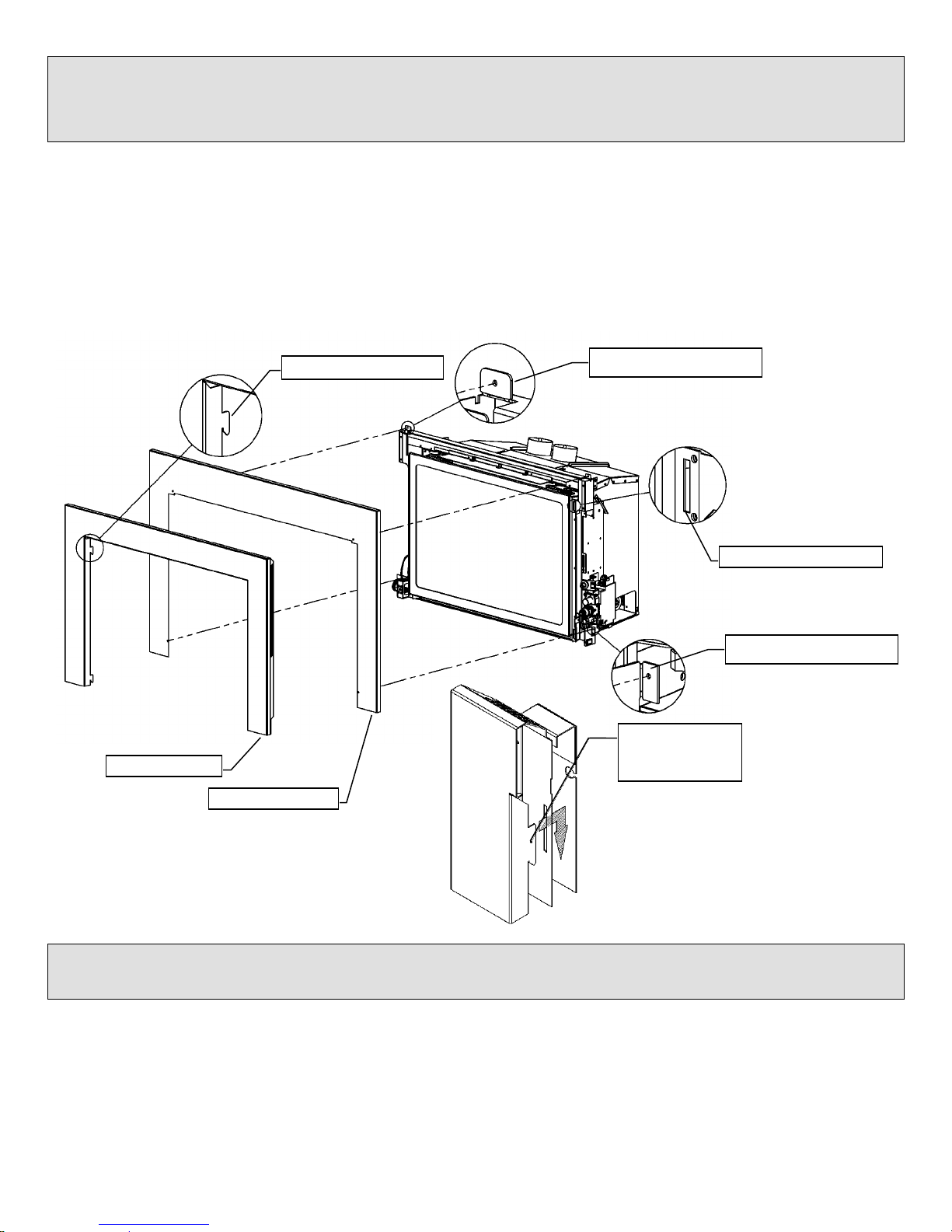
Installation of IDV26 / IDV33 / IDV43
Using Steel Studs and Concrete Board over Wood Burning Fireplace
USE STEEL STUDS
USE CONCRETE BOARD ON
FRONT AND AROUND STEEL
STUD ENCLOSURE FOR INSERT
MUST BE SEALED TO AVOID HEAT
ENTERING OLD ENCLOSURE
EXISTING ZERO CLEARANCE
WOOD BURNING / MASONRY
FIREPLACE
MUST BE SEALED TO AVOID HEAT
ENTERING OLD ENCLOSURE
6
Brick facing may be removed and replaced with non-combustible materials such as steel studs and
concrete board. The opening between the firebox and non-combustive materials must be sealed so
as the heat cannot run between the face of the wood fireplace and the re-facing materials.
Insert must be pulled out so the appliance is flush with the finishing materials and the clean view kit is
proud of the finished non-combustible enclosure (wood burning fireplace).
7
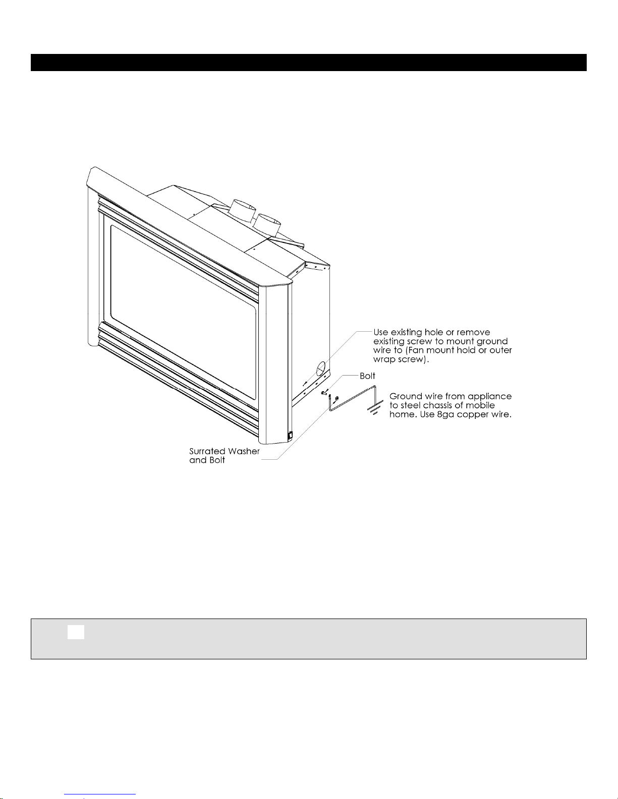
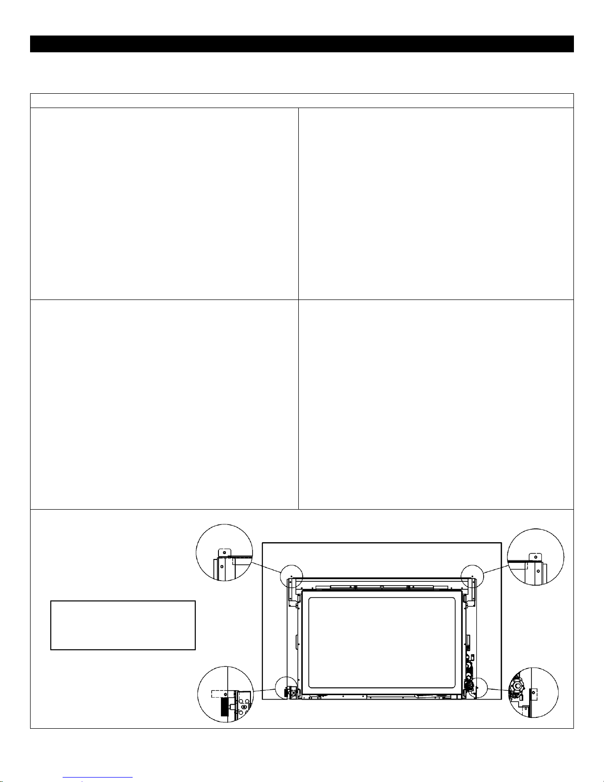
Mobile Home/Manufactured Housing Installation
This Direct Vent System Appliance must be installed in accordance with the manufacturer’s installation instructions and
the Manufactured Home Construction and Safety Standard Title 24 CFR, Part 3280, or the current Standard for Fire
Safety Criteria for Manufactured Home Installation, Sites, and Communities ANSI/NFPA 501A, and with CAN/CSA Z240
MH Mobile Home Standard in Canada.
THIS APPLIANCE MAY BE INSTALLED IN MANUFACTURED (MOBILE) HOMES AFTER FIRST SALE.
Please follow the current ANSI/NFPA 70 National Electrical Code in the USA and CAN/CSA C22.1 Canadian National
Electrical Code in Canada.
An appliance must be grounded to the steel chassis of the home with 8ga. copper wire using a serrated or star washer to
penetrate paint or protective coating to insure grounding.
Use carriage bolt at the attachment point (see diagram above) to secure the appliance to the floor.
Bedroom approved.
Warning: Do not compromise the structural integrity of the manufactured home wall, floor or ceiling,
during installation of appliance or venting.
For required venting components see venting installation in appropriate section of this manual.

Warnings, Installations and Operations
WARNING
FOR SAFE INSTALLATION AND OPERATION OF YOUR GAS FIREPLACE PLEASE NOTE THE FOLLOWING:
1. Do not clean when the glass is hot.
2. Do not use abrasive cleaners.
3. Using a substitute glass will void all product warranties.
4. For safe operation, glass doors must be closed.
5. When purging the gas line, the glass front must be removed.
6. Do not strike or abuse glass. Take care to avoid breakage.
7. Do not alter gas orifice.
8. No substitute materials may be used other than factory
supplied components.
9. This appliance gives off high temperatures and should be
located out of heavy traffic areas and away from furniture and
draperies.
10. Children and adults should be alerted to the hazards of the high
surface temperatures of this appliance and should stay away to avoid burns or ignition of clothing.
11. Young children should be carefully supervised when they are in the same room as the appliance. Toddlers, young children
and others may be susceptible to accidental contact burns. A physical barrier is recommended if there are at risk individuals
in the house. To restrict access to a fireplace or stove, install an adjustable safety gate to keep toddlers, young children and
other at risk individuals out of the room and away from hot surfaces.
12. Under no circumstances should any solid fuels (wood, paper) be used in this appliance.
13. Under no circumstances should this appliance be modified. Any parts that have to be removed for servicing should be
replaced prior to operating this appliance.
14. Any safety screen, guard, or barrier removed for servicing an appliance must be replaced prior to operating the appliance.
15. Installation and repair should be done by a qualified service person. The appliance should be inspected before use and at
least annually by a professional service person. More frequent cleaning may be required due to excessive lint from
carpeting, bedding material, et cetera. It is imperative that control compartments, burners and circulating air passageways
of the appliance be kept clean. Make sure that the gas valve and pilot light are turned off before you attempt to clean this
unit.
16. Clothing or other flammable material should not be placed on or near the appliance. This appliance should not be used as a
drying rack for clothing nor should Christmas stockings or decorations be hung from it.
17. Do not use this heater if any part has been under water. Immediately call a qualified service technician to inspect the heater
and to replace any part of the control system and any gas control which has been under water.
18. Do not operate appliance unless completely installed as per installation instructions.
19. Failure to position the parts in accordance with these diagrams or failure to use only parts specifically approved with this
appliance may result in property damage or personal injury.
20. WARNING: Do not operate appliance with the glass front removed, cracked or broken. Replacement of the glass
should be done by a licensed or qualified service person.
21. The appliance area must be kept clear and free from combustible materials, gasoline, and other flammable vapors and
liquids.
22. The front of the fireplace gives off high temperatures that could ignite combustible material which is kept close to the front of
the unit.
23. Ensure that power to the Fireplace is turned off before servicing.
24. Do not operate this Fireplace without the glass front or with a broken glass.
25. Improper installation, adjustment, alteration, service or maintenance can cause injury or property damage. Refer to the
owner’s information manual provided with this appliance. For assistance or additional information consult a qualified
installer, service agency, or the gas supplier.
26. Operation of this appliance when not connected to a properly installed and maintained venting system or tampering with the
blocked vent shutoff system can result in carbon monoxide (CO) poisoning and possible death.
27. This appliance is equipped with a three-prong (grounding) plug for your protection against shock hazard and should be
plugged directly into a properly grounded three-prong receptacle. Do not cut or remove the grounding prong from this plug.
8
Installation Regulations
This gas appliance must be installed by a qualified installer in accordance with local building codes, or in the absence of local codes, with the current
CAN/CSA-B149.1 or .2 Installation Code (in Canada) or the current National Fuel Gas Code Z223.1- NFPA 54 when installed in the United States.
This appliance, when installed, must be electrically connected and grounded in accordance with local codes, or in the absence of local codes, with the
current CSA C22.1 Canadian Electrical Code or with the National Electrical Code; ANSI/NFPA 70 when installed in the United States.
In the U.S.A. Thermostats are not permitted for Vented Gas Fireplaces (ANSI Z21.50b-Decorative).

Gas fired appliances may be used only for supplemental heat and/or decorative purposes and under no circumstances shall they
NOTE: It is recommended that a Carbon Monoxide (CO) Detector be installed in or near bedrooms and on all levels of your home.
Place a detector about 15ft [4.5m] outside the room that houses your gas appliance.
Certified for installation in a bedroom or bed/sitting room. In Canada must be installed with listed millivolt thermostat.
In the U.S.A. Thermostats are not permitted for Vented Gas Fireplaces (ANSI Z21.50b-Decorative).
In USA see local codes.
9
provide a primary heat source.
This appliance must not be connected to a chimney flue serving a separate solid-fuel burning appliance.
Operations and Maintenance Instructions
For safe installation and operation note the following:
• Venting systems should be periodically examined by a qualified agency.
• The flow of combustion and ventilation air must not be obstructed.
• The Burner/Log Assembly has been engineered and permanently adjusted for proper flame control.
• Periodically remove the logs from the grate assembly and vacuum any loose particles from the grate and burner areas. See Log
Placement page to remove logs. Vacuum burner parts and replace logs.
• Never use your gas fireplace as a cooking device.
• Label all wires prior to disconnection when servicing controls. Wiring errors can cause improper and dangerous operation. Verify
proper operation after servicing.
Installation Requirements for the Commonwealth of Massachusetts
In the Commonwealth of Massachusetts, the installer or service agent shall be a plumber or gas fitter licensed by the Commonwealth.
When installed in the Commonwealth of Massachusetts or where applicable codes; the unit shall be installed with a CO detector per the
requirements listed below.
1. For direct-vent appliances, mechanical-vent heating appliances or domestic hot water equipment, where the bottom of the vent
terminal and the air intake is installed below four feet above grade the following requirements must be satisfied:
A. If there is not one already present, on each floor level where there are bedroom(s), a carbon monoxide detector and alarm
shall be placed in the living area outside the bedroom(s). The carbon monoxide detector shall comply with NFPA 720.
B. A carbon monoxide detector shall be located in the room that houses the appliance or equipment and shall:
Be powered by the same electrical circuit as the appliance or equipment such that only one service switch services
both the appliance and the carbon monoxide detector;
Have battery back-up power;
Meet ANSI./UL 2034 Standards and comply with NFPA 720; and
Have been approved and listed by a Nationally Recognized Testing Laboratory as recognized under 527 CMR.
C. A Product-approved vent terminal must be used, and if applicable, a Product-approved air intake must be used.
Installation shall be in strict compliance with the manufacturer’s instructions. A copy of the installation instructions shall
remain with the appliance or equipment at the completion of the installation.
D. A metal or plastic identification plate shall be mounted at the exterior of the building, four feet directly above the location of
vent terminal. The plate shall be of sufficient size to be easily read from a distance of eight feet away, and read “Gas Vent
Directly Below”.
2. For direct-vent appliances, mechanical-vent heating appliances or domestic hot water equipment where the bottom of the vent
terminal and the air intake is installed above four feet above grade the following requirements must be satisfied:
A. If there is not one already present, on each floor level where there are bedroom(s), a carbon monoxide detector and alarm
shall be placed in the living area outside the bedroom(s). The carbon monoxide detector shall comply with NFPA 720.
B. A carbon monoxide detector shall:
Be located in the room that houses the appliance or equipment;
Be either hard-wired or battery powered or both; and
Shall comply with NFPA 720.
A Product-approved vent terminal must be used, and if applicable, a Product-approved air intake must be used. Installation shall be in
strict compliance with the manufacturer instructions. A copy of the installation instructions shall remain with the appliance or equipment
at the completion of the installation.
For the state of Massachusetts a T-handle gas shut-off valve must be used on a gas appliance. This T-handle gas shut-off valve must be listed and
approved by the state of Massachusetts. This is in reference to the state of Massachusetts state code CMR238.
-Glass Safety- All Units
-Termination Cap Safety- All Units
WARNING:
WHEN THE HORIZONTAL VENT TERMINATION IS ACCESSIBLE
A CERTIFIED GUARD (SAFETY CAGE) SHALL BE INSTALLED.
10
IT IS THE RESPONSIBILITY OF THE
HOME OWNER TO ENSURE THAT
NO ONE TOUCHES A HOT
APPLIANCE.
If the barrier becomes damaged, the barrier
shall be replaced with the manufacturer’s
barrier for this appliance.
Any safety screen, guard, or barrier removed for
servicing the appliance, must be replaced prior
to operating the appliance.
Children and adults should be alerted to the
hazards of the high surface temperatures of this
appliance and should stay away to avoid
burns or ignition of clothing.
Do not clean when the glass is hot.
Young children should be carefully supervised when they are in the same room as the appliance. Toddlers,
young children and others may be susceptible to accidental contact burns.
A physical barrier is recommended if there are at risk individuals in the house. To restrict access to a fireplace or
stove, install an adjustable safety gate to keep toddlers, young children and other at risk individuals out of the
room and away from hot surfaces.
Do not leave the fireplace remote control where it is accessible to children.
SAFETY CAGES ARE AVAILABLE FOR ALL HORIZONTAL VENT TERMINATIONS.
CHECK WITH YOUR DEALER.
TERMINATION CAP IS HOT! Do not place flammable materials on or within 24 inches of termination caps.
It is imperative that the vent termination be located observing the minimum clearances as shown in manual.
There must not be any obstruction such as bushes, garden sheds, fences, decks or utility buildings within 24"
from the front of the termination plate.
Do not locate termination where excessive snow or ice build-up may occur. Be sure to check vent termination
area after snow falls and clear to prevent accidental blockage of venting system. When using snow blowers,
make sure snow is not directed towards vent termination area.
Venting terminal shall not be recessed into a wall or siding.

Important Information
11
INSTALLATIONS
The following label (supplied with the gas fireplace insert) must be attached with rivets or screws to the inside of the
firebox of the fireplace into which it is installed:
Cutting any sheet-metal parts of the fireplace, in which the gas fireplace insert is to be installed, is prohibited.
If the factory-built fireplace has no gas access hole(s) provided, an access hole of 1.5 in (37.5 mm) or less may be drilled
through the lower sides or bottom of the firebox in a proper workmanship like manner. This access hole must be plugged
with non-combustible insulation after the gas supply line has been installed.
The fireplace flue damper can be fully blocked open or removed for installation of the gas fireplace inse rt.
Ensure that existing chimney cleanouts fit properly.
refractory, glass doors, screen rails, screen mesh and log grates can be removed from the fireplace before installing the
gas fireplace insert.
Smoke shelves, shields and baffles may be removed if attached by mechanical fasteners.
Trim panels or surrounds must not seal ventilation openings in the fireplace.
The fireplace and fireplace chimney must be clean and in good working order and con stru cted of non-combustible
materials.
MAINTENANCE
If for any reason the vent air intake system is disassembled, re-install and re-seal per the inst ructions provided for the
initial installation. See “Installation of Vent Pipe” section.
It is recommended to annually inspect and clean the Burner System to prevent malfunction a nd / or sooting. This
operation should be performed by your dealer or a qualified technician. Refer to Burner System Maintenance section.
Venting systems should be periodically examined by a qualified age ncy.
Periodically remove the logs from the grate assembly and vacuum any loose particles from the grate and burner areas.
See Log Placement page to remove logs. Vacuum burner parts and replace logs.
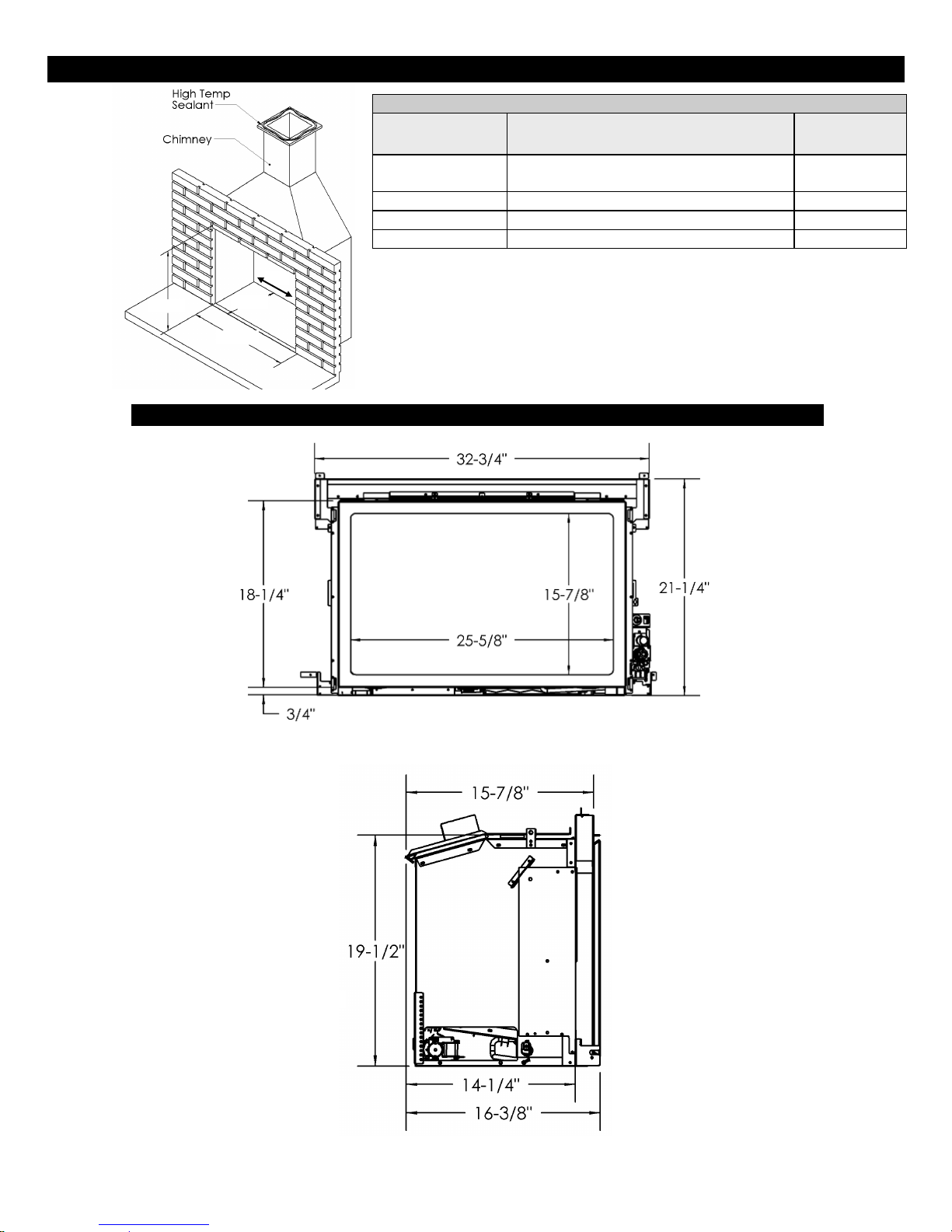
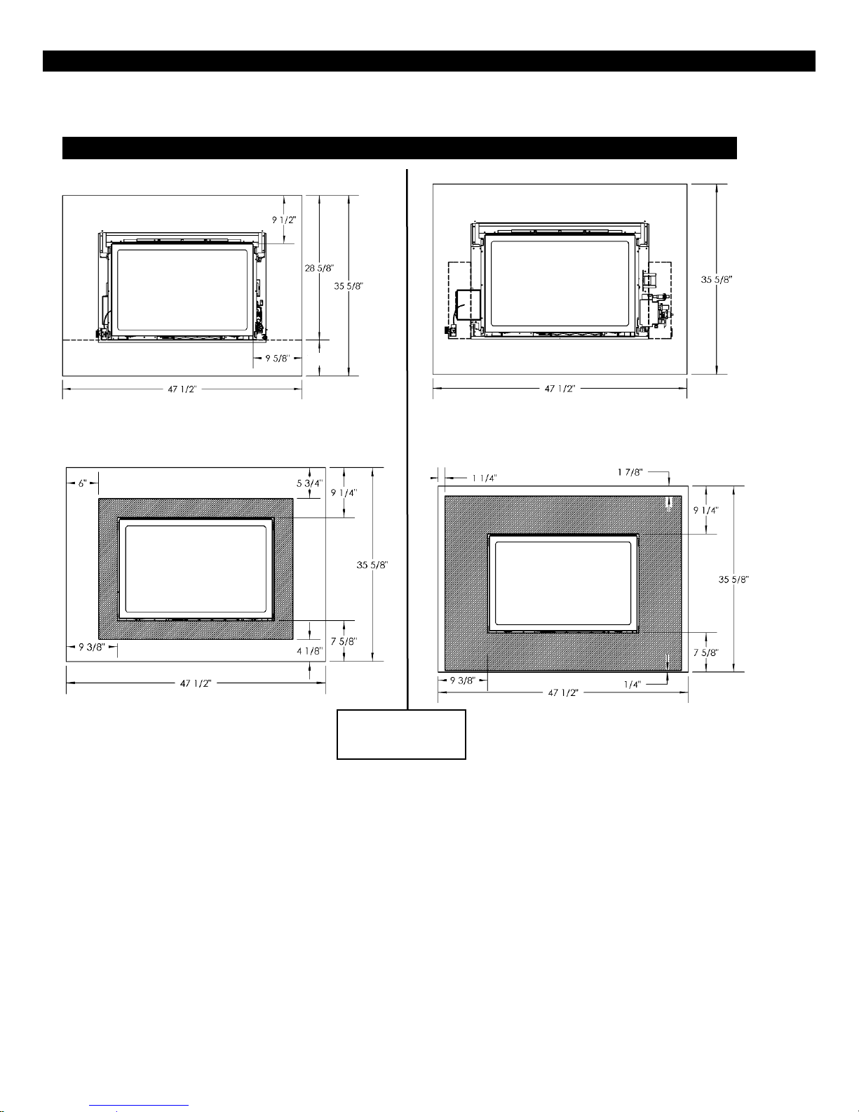
IDV26 Insert Dimensions and Sizing
Minimum Opening Dimensions
Dimension
Components In
Components
Out
“A” Front Width:
33” Centered in existing fireplace
*31” Not Centered in existing fireplace
28”
“B” Height:
19-1/2”
19-1/2”
“C” Depth:
14-1/4”
14-1/4”
“D” Back Width:
22”
22”
Note: Valve Control Components can be placed either inside the opening
(Components In) or outside the opening (Components Out).
Units are shipped with Control Components in.
For instructions on changing to Components Out refer to Control Components
Outside the Opening- COMPONENTS OUT.
“C”
“A”
“B”
Base Model IDV26
Front View
Left Side View
“D”
12
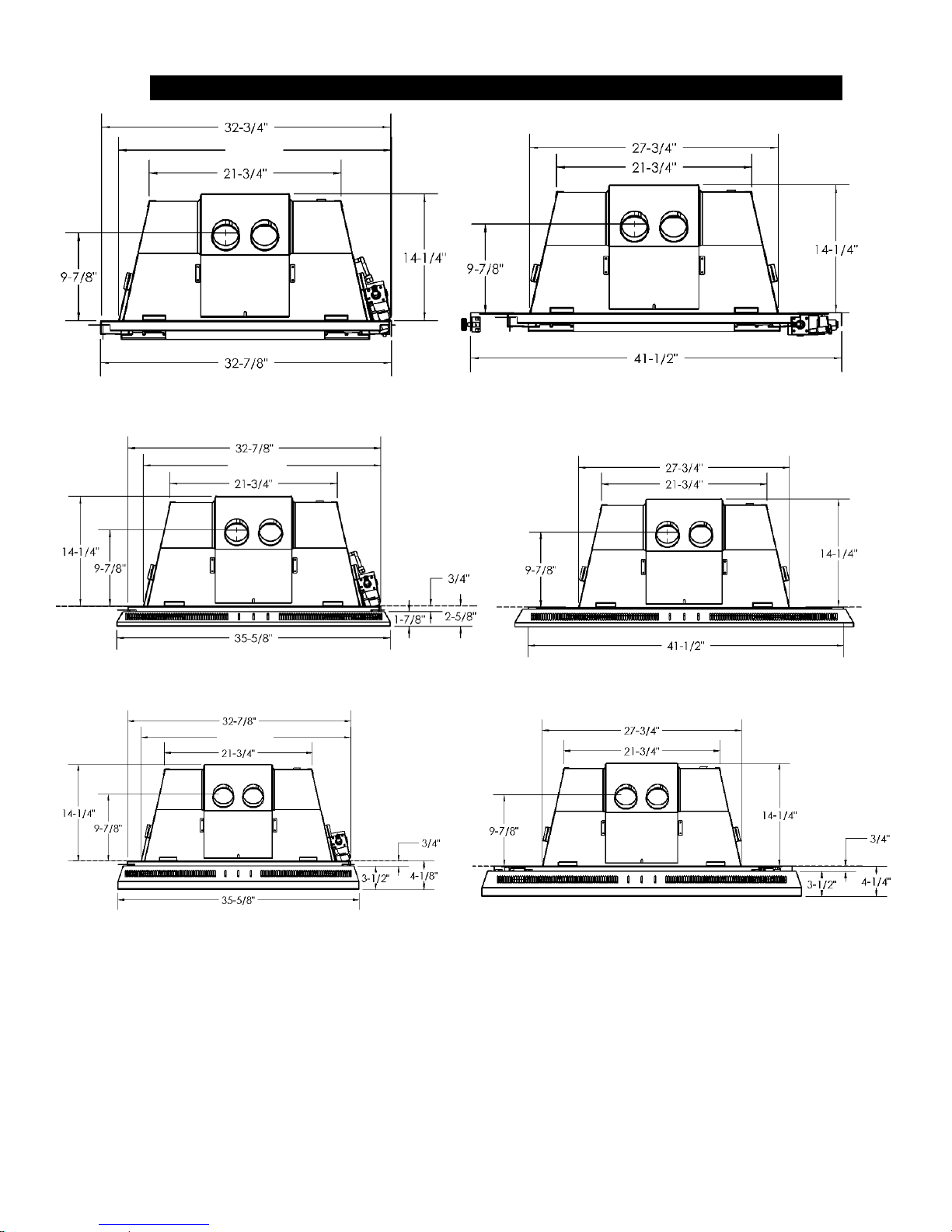
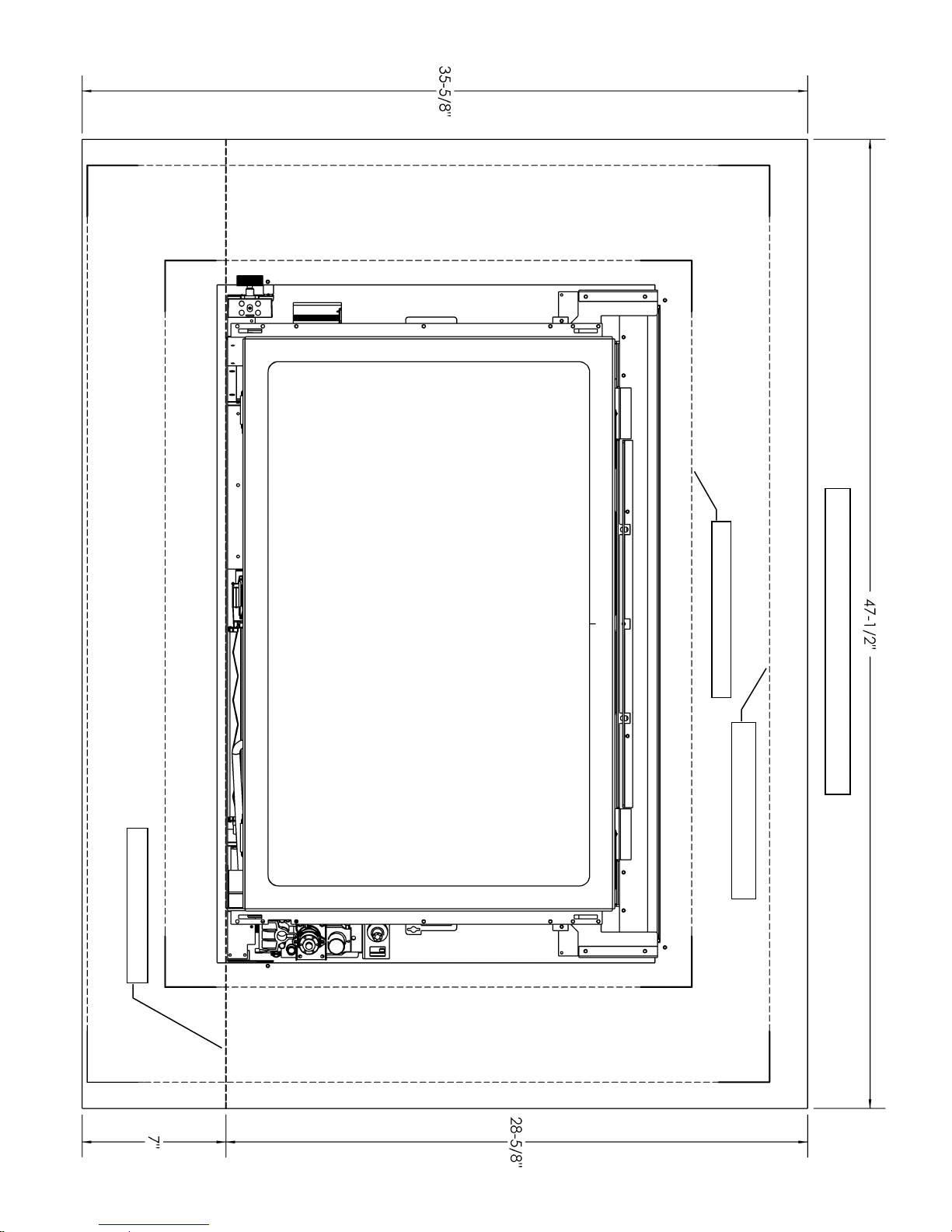
Top View- Components In
(As Shipped)
Components In Components Out
Top View- Components In
With I26CV1
Top View- Components Out
30-7/8”*
30-7/8”*
Top View- Components Out
With I26CV2
Top View- Components In
With I26CV3
Top View- Components Out
With I26CV4
30-7/8”*
13
Top View Dimensions
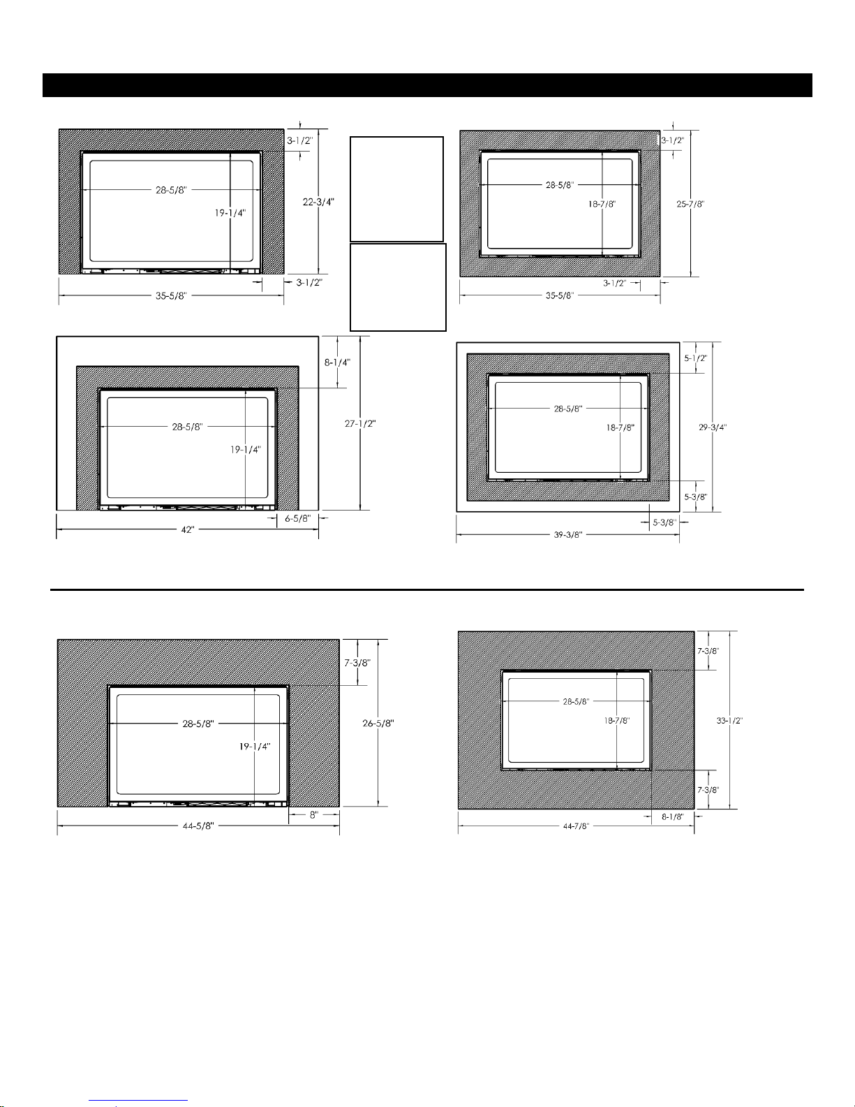
I26CV Clean View and Surround Sizes
Clean View Kit I26CV1, I26CV3
Picture Frame Clean View Kit
I26CVPF1, I26CVPF3
Clean View Kit I26CV1, I26CV3 with
Rectangular Surround I26S1
Picture Frame Clean View Kit I26CVPF1, I26CVPF3,
with Picture Frame Surround I26SPF1
Clean View Kit I26CV2, I26CV4
Picture Frame Clean View Kit
I26CVPF2, I26CVPF4
Dimensions
are to
Inside Edge
of Clean
View.
Note: If a
completely tight
fit to the wall is
desired, CV
requires I26S1
or I26SPF1.
14
*The Clean Views and Surrounds in this section must be used with Valve Control Components inside the opening (as shipped).
*The Clean Views in this section can be used with Valve Control Components inside or outside the opening, HOWEVERif controls are outside, these Clean Views MUST be used to cover valve controls.
IDV26 I26SU Universal Surround
Components In Components Out
Picture Frame Clean View Kit I26CVPF1 or
I26CVPF3 With Universal Surround I26SU
Picture Frame Clean View Kit I26CVPF2 or
I26CVPF4 With Universal Surround I26SU
I26SU must be trimmed to fit around
Valve Control Components.
7”
Dimensions are to
Inside Edge of
Clean View.
15
A Universal Surround is available for the IDV26. This is provided as a flat sheet which mounts onto the unit and is to be
cut to size and formed by the installer. Flat Surround Shown dimensioned.
I26SU installed on unit.
Refer to Worksheet on next page to trim for use as a 3-sided surround or for a custom layout.
I26SU UNIVERSAL SURROUND
I26CVPF1 or I26CVPF3
I26CVPF2 or I26CVPF4
BOTTOM OF UNIT
16
I26CV - Surround Installation
-Clean View (CV) Attachment
-Valve Access
NOTE: The Clean View Surround needs to be removed in order to access the Glass Door, access the valve, and
service the unit.
Surround Mount Tab
Surround Mount Tab
Clean View Mount Tab
Clean View Mount Slot
Clean View Kit
Optional Surround
Insert Tab into
Slot to mount the
Clean View Kit.
17
1. Optional Surround Kit (I26S, I26SPF, I26SU) is fastened to the insert by pulling up [4] Surround Mount Tabs on the
unit and using [4] #6 screws provided with surround.
2. Insert the Clean View (I26CV1 or I26CV3, I26CV2 or I26CV4, I26CVPF1 or I26CVPF3, I26CVPF2 or I26CVPF3)
Mounting Tab into the Clean View Mounting Slots (four [4] places) and lower the Clean View kit into place.
3. Valve Access: To access valve simply remove Clean View. Replace Clean View as per item [2] above once
adjustments to valve have been completed.
Valve positioned as per manufacturer’s instructions.
I26S1 / I26SPF1 / I26SU Surround Installation
Bend Up All 4 Mount Tabs
Top Left
Top Right
Bottom Left
Bottom Right
Place Surround onto unit and
line up holes in mount tabs with
holes in Surround. Attach with
screws provided.
18
Component List: I26S1 / I26SPF1 / I26SU Surround, [Qty 4] #6 Black Combo Screws
I26CV2 / I26CV4 / I26CVPF2 / I26CVPF4 Wide Clean View Installation
Component List:
Fan Control Switch Bracket
On/Off Switch Bracket
Remove Fan Control Switch From Current Position.
Remove On/Off Switch and original mount bracket.
Attach Fan Control Switch Extension Bracket using [2] #6
Combo Screws as shown.
Attach On/ Off Switch Extension Bracket using [2] #6
Combo Screws as shown.
Mount Switch & route wiring as shown.
Mount Switch & route wiring as shown.
-Components Out-
Insert Mount Tabs into slots in unit and lower Clean View into place. Refer to Clean View Attachment.
1
1
2
2
3
3
19
I26CV2 / I26CV4 / I26CVPF2 / I26CVPF4 Clean View
On/ Off Switch Extension Bracket
Fan Control Switch Extension Bracket
[4] #6 Black Combo Screws
Components In (As Shipped):

Fan Control Switch Bracket
On/Off Switch Bracket
NOTE: If Ground is attached to Side Component Plate,
remove and fasten to side of appliance with a DT Screw.
Remove Fan Control Switch From Current Position.
Attach Fan Control Switch Extension Bracket using [2] #6
Combo Screws.
Mount Switch & route wiring as shown.
Remove On/Off Switch and original mount bracket.
Attach On/ Off Switch Extension Bracket using [2] #6
Combo Screws as shown.
Mount Switch & route wiring as shown.
Insert Mount Tabs into slots in unit and lower Clean View into place. Refer to Clean View Attachment.
Components Out
1
2
2
3
3
20
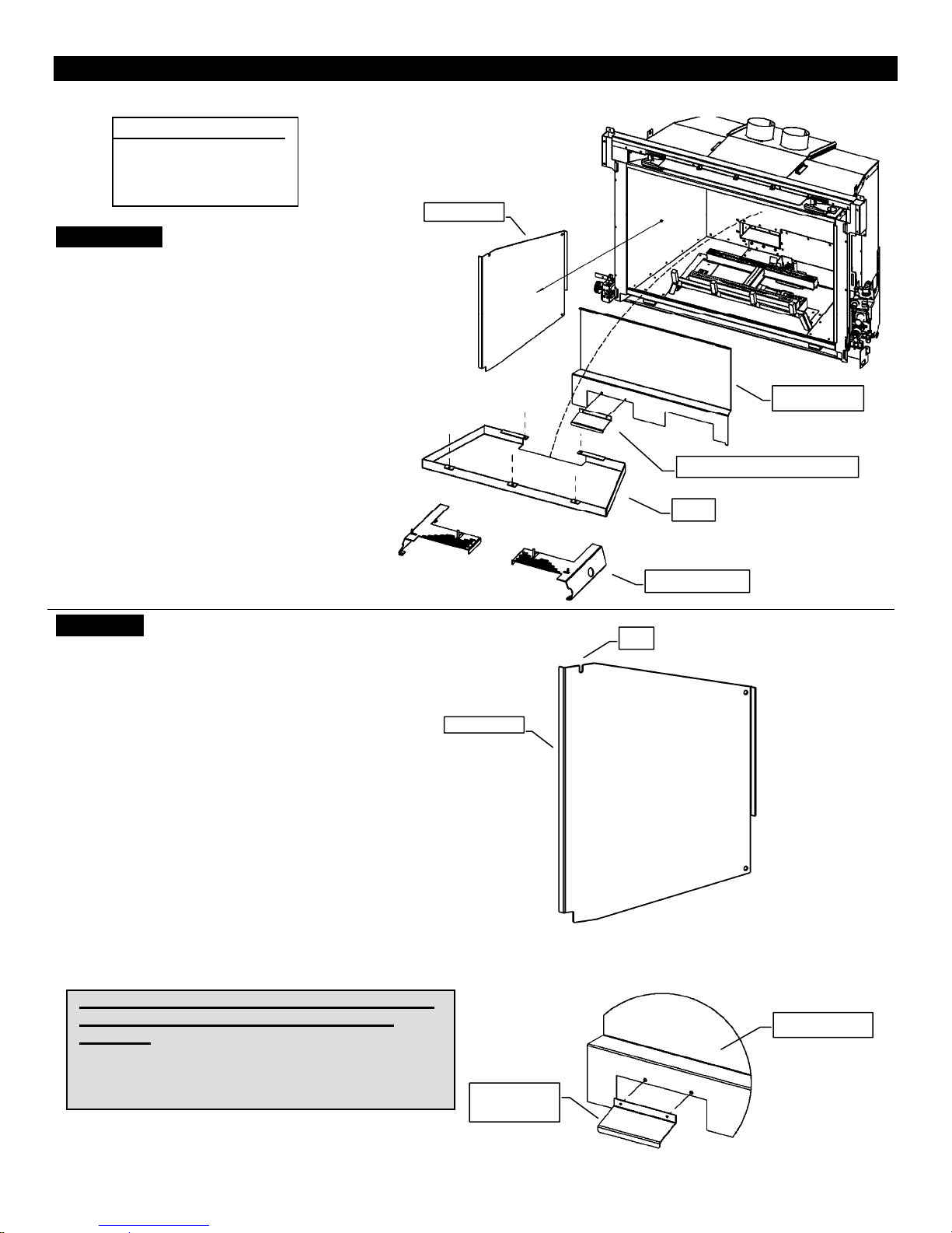
IDV26PRL - Porcelain Liner Panels-
21
IDV26PL Parts List:
-1 Back Panel
-1 Right Side Panel
To Remove:
-1Left Side Panel
1. Remove Log Supports. Remove
the [5] screws in the firebox top
holding the Baffle in place.
2. Remove Back Panel. Unscrew and
remove the Back Panel.
tilt to remove. NOTE: If you will be
installing a porcelain Back Liner,
unscrew Back Panel Air Deflector
and install on porcelain Back Liner.
3. Remove Side Panels (if present).
Remove screw. Tilt and slide Side
Panels out of fireplace.
Slide and
Side Panel
Back Panel
Back Panel Air Deflector
Baffle
To Install:
1. Install Side Panels. If you are using Side
Panels, install them first. Tilt and slide
Side Panels into place. Secure with screw
in side of firebox.
2. Install Back Panel. Ensure that Back
Panel Air Deflector is in place on Back
Panel (See Illustration). Place Back Panel
up against the back of the Firebox and
reinstall the [2] Screws in firebox top.
Then slide lower Liner Retainer Clip
(located on bottom of firebox behind
burner) up to bottom of Back Panel &
tighten.
3. Replace Baffle. Replace Baffle and
proceed with Log or Rock/Glass Tray
setup.
Note: Warping and Discoloration of Porcelain or
Painted Metal Liners Is Not Covered Under
Warranty.
Both Porcelain and Painted Metal Liners may discolor
and warp during normal operation of your appliance.
This is normal, and not considered a defect
.
Side Panel
Back Panel
Air Deflector
Log Supports
Top
Back Panel
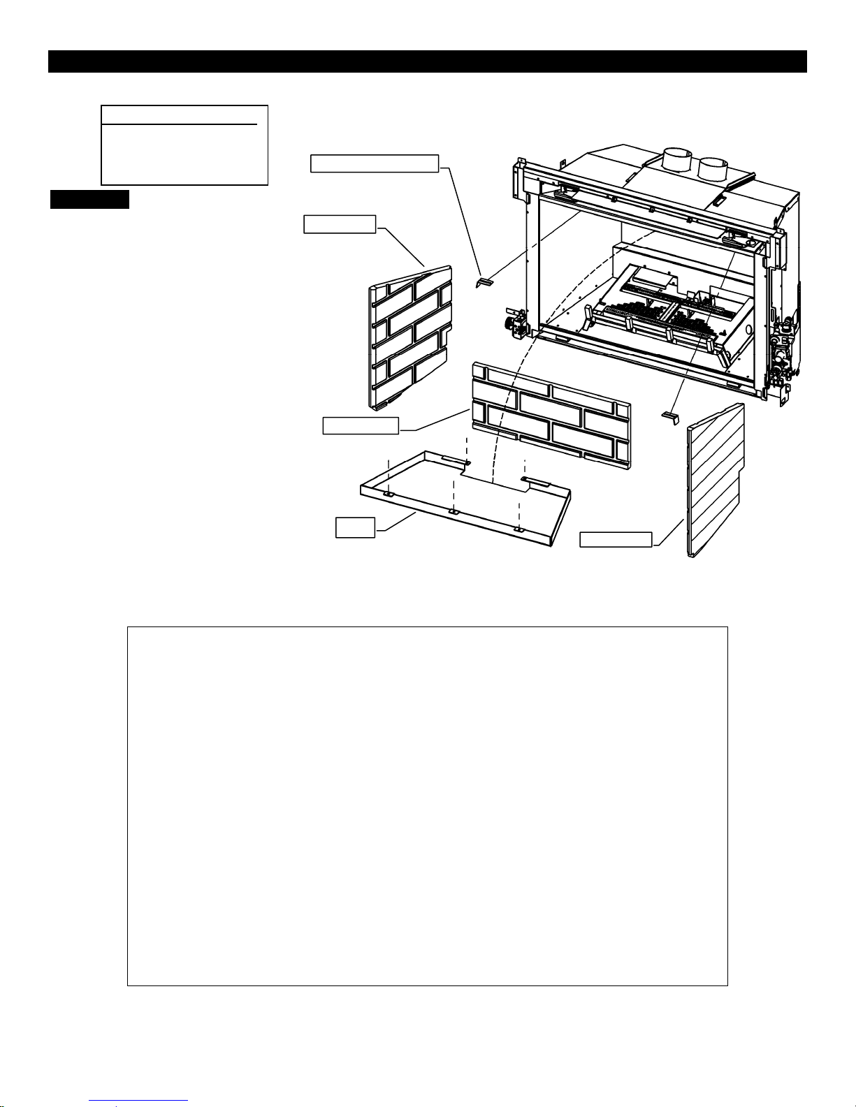
IDV26RL - Brick Liner Panels-
22
IDV26RL Parts List:
-1 Back Panel
-1 Right Side Panel
-1Left Side Panel
To Install:
1. Remove the Baffle.
Remove the [5] screws in
the firebox top holding the
Baffle in place. Remove
the [2] Liner Retainer Clips
in the firebox top also.
2. Install Back Panel. Place
Back Panel on the rear
ledge inside the firebox.
3. Install Side Panels. Twist
and rotate Side Panels into
place. Secure with Liner
Retainer Clips in top of
firebox..
Liner Retainer Clip
Side Panel
Back Panel
4. Replace Baffle. Replace
Baffle and proceed with
Log or Rock/Glass Tray
setup.
Baffle
Side Panel
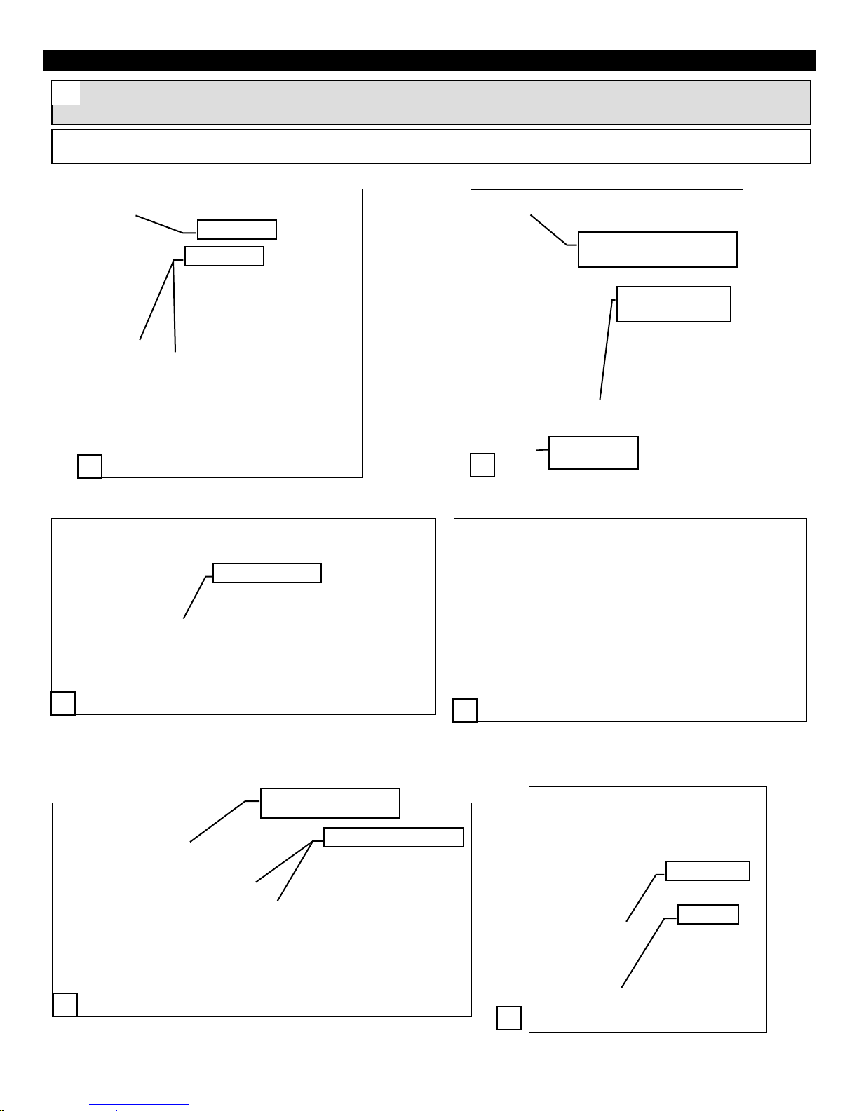
IDV26 -Millivolt- -Control Components Outside the Opening- -COMPONENTS OUT-
Remove [2] 3/8” nuts holding valve onto Component
Panel. Unhook valve from Component Panel.
Remove Component Panel, Switch Bracket, and Side Plate.
Remove knockout with side cutters, if present.
Discard knockout.
Optional- Connect flex (Not included. Order PN#
FP15GC) to inlet side of valve. This can then be
connected to the gas supply and routed through the
channel inside the fireplace.
Route valve connections through the opening.
Mount Component Panel on opposite side of valve.
NOTE: It is not necessary to disconnect pilot lines and gas supply line from valve to complete this procedure. Care
should be taken to ensure that the gas and pilot lines are not damaged during handling. These lines are fragile.
Warning: Failure to position the parts in accordance with these diagrams or failure to use only parts specifically
approved with this appliance may result in property damage or personal injury.
Route Through Opening
Remove Knockout
Remove Nuts
Unhook Tab
Unscrew Component Panel
[1] Screw
Remove Side Plate
[4] Screws
Switch Bracket
[2] Screws
Hook Tab
Refasten Nuts
1.
2.
3.
4.
5.
6.
Route Through Opening
(Optional)
23
This procedure must be done Before the unit is inside the enclosure.
Fasten Component Panel at top.
Replace Side Plate. Attach
Component Panel and
Extended Switch Bracket.
Procedure is complete.
IDV26 -IPI- -Control Components Outside the Opening- -COMPONENTS OUT-
Ready to begin.
Remove All Components from Component Panel.
Remove Component Panel from fireplace.
Remove Side Plate and knockout if present (see millivolt
section). Place Component Panel on other side of valve.
Optional- Connect flex (Not included. Order PN#
FP15GC) to inlet side of valve. This can then be connected
to the gas supply and routed through the channel inside the
fireplace. (see millivolt section).
Fasten Component Panel
[2] Screws
Replace Side
Plate
Extended Switch Bracket
Attach Component
Panel
Component Panel
Component Panel
IPI Module
7.
8.
9.
1.
2.
3.
4.
Side Plate
NOTE: Some
screws may need to
be cut flush to the
component mount
plates for a tight fit
against wall.
24
*Refer to Millivolt section for more detailed photos & instructions.
Replace Side Plate. Fasten Component Panel at top &
bottom. Attach Component Panel and Extended Switch
Bracket (see millivolt section).
Procedure is complete.
MILLIVOLT- COMPONENTS OUT
IPI- COMPONENTS OUT
5.
6.
Fasten to Component
Panel with Zip Tie.
NOTE: Some screws may need to be cut flush to
the component mount plates for a tight fit against
wall.
25
IDV26 Fan Speed Control Outside COMPONENTS OUT
Left Side of Fireplace
Connect Fan Switch to Extension Bracket.
Install Component Panel and Fan Switch Extension in new
position.
Remote Receiver Location.
Warning: Failure to position the parts in accordance with these diagrams or failure to use only parts specifically
approved with this appliance may result in property damage or personal injury.
Remove Component Panel
[1] DT Screw
Remove Fan Switch
1.
2.
3.
Install Fan Switch
Extension Bracket
[3] Screws
Replace Component Panel in New
Position [2 Screws]
4.
26
NOTE: It is not necessary to disconnect fan wiring to complete this procedure.
This procedure must be done before the unit is inside the enclosure.
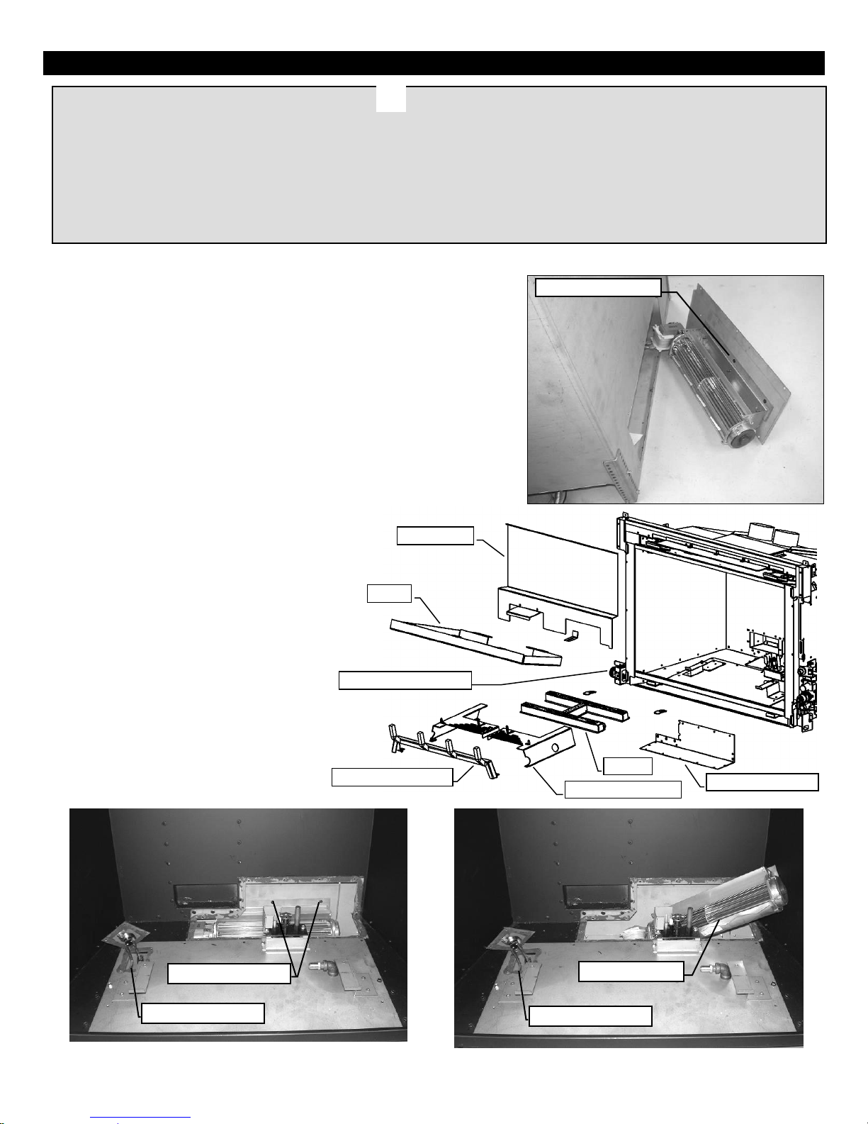
IDV26 Fan Removal / Installation
1. Remove Grate Bar Assembly, Burner Trim
Plates, and Burner. Then remove the [5]
screws in the firebox top holding the Baffle
in place. Remove the Baffle. Then
unscrew and remove the Back Panel.
2. Remove Fan Access Cover (15 screws). It
is located on the back and bottom right
hand corner. The fan area will now be
exposed (See photo below).
3. Unscrew the [2] screws and remove fan.
Fan needs to be twisted and rotated
slightly. (See photo below).
4. Replace all components and seal Fan
Access Cover and Thermodisk Plate with
Millpac.
5. Verify proper operation after servicing.
WARNING
Electrical Grounding Instructions
This appliance is equipped with a three prong (grounding) plug for your protection against shock hazard and should be plugged directly
into a properly grounded three-prong receptacle. Do not cut or remove the grounding prong from this.
Before Servicing
1. Ensure all power supply is shut off.
2. Label all wires prior to disconnecting when servicing control. Wiring errors can cause improper and dangerous operation.
3. For fan servicing: Vacuum and clean lint/dirt build-up on the fan blades and motor.
When resealing the Fan Access Panel, use High Temp Silicone or Millpac.
Fan Access Cover
Back Panel
Baffle
Burner
Burner Trim Plates
Variable Speed Switch
Grate Bar Assembly
Thermodisk Location
Remove [2] Screws
Thermodisk Location
Twist and Rotate
#6 Black Screws.
27
The fan can be accessed from the back of the unit (which is easiest on an uninstalled unit) or through the inside
of the firebox.
To remove or install the fan from the back of the unit, remove the
Fan Access Cover from the back of the fireplace. The fan will be attached
to this cover (See right).
Thermodisk Location: Note the location of the Thermodisk in the
photograph below.
Variable Speed Switch Location: Note the location of the Variable
Speed Switch in the illustration below.
To remove or install the fan through the inside of the firebox, refer
to the procedure below.
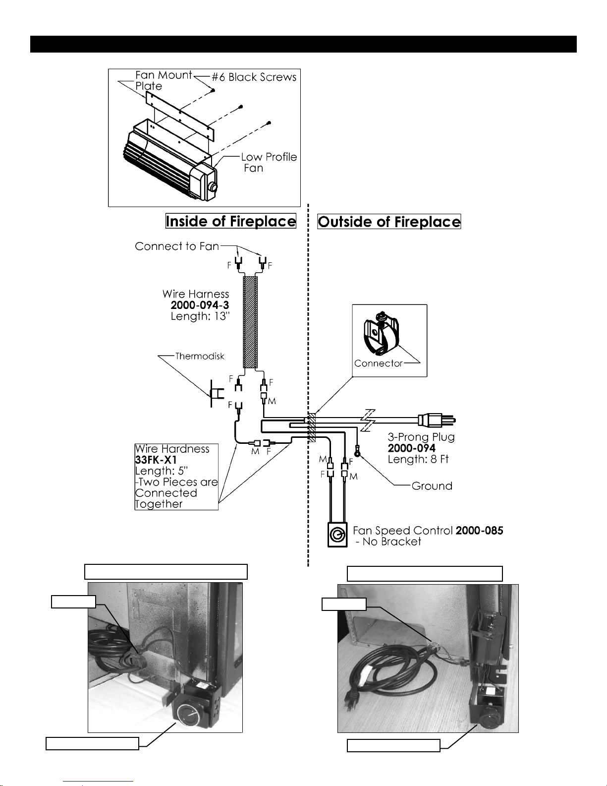
IDV26 Fan - Wiring IDV26
Components In –Left Side of Unit
Components Out- Left Side of Unit
Variable Speed Switch
Variable Speed Switch
Connector
Connector
28
IDV26 Remote Receiver Location All Units
Route Wiring Harness 1001-P904SI
Under Fan Inside Fireplace.
Route Wiring Harness 1001-P904SI
Under Fan Inside Fireplace.
Restrain Harness With [2]
Zip Ties Through Holes
Provided in Fireplace.
Pull up Mount Tabs &
Mount Remote Receiver
29
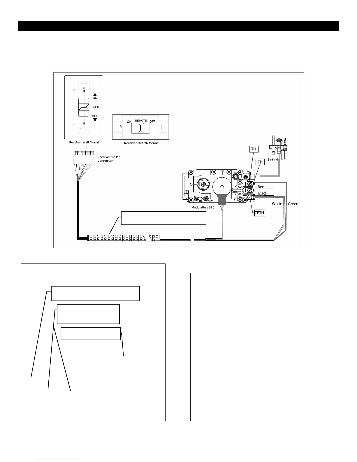
Connecting to the Gas Valve
The wiring harness for the Proflame GTM system has two wires labeled “TH” & “TPTH”. Connect the wires to the gas
valve as labeled. (TH to TH and TPTH to TPTH). Additionally there is a connector labeled “Motor”. Connect this “Motor”
connector to the stepper motor on the gas valve (if present).
Left Side of Fireplace
Components In (As Shipped) Components Out Remote Receiver Location.
 Loading...