

Page 1
Installation Instructions
Model Number IDV33-IDV36 Gas Fired Direct Vent Room
Heater inserts
Model IDV 33
Listed Certified for USA. and Canada
Certified to: ANSI Z21.88a-2000, CSA 2.33A-2000, CGA 2.17-M91, CSA P.4.1-02
Model IDV 36 Listed Certified for USA. and Canada
Certified to: ANSI Z21.88b/CSA 2.33b-2003, CSA P.4.1-02
Read this complete manual before beginning installation.
These instructions must be kept with the unit for future reference.
FOR YOUR SAFETY
Warning: Improper installation, adjustment, alteration, service
or maintenance can cause property damage, personal injury or
loss of life. Refer to this manual. Installation and service must
be performed by a qualified installer, service agency or the gas
supplier.
Do not store or use gasoline or other flammable vapors and
liquids in the vicinity of this or any other appliance.
What To Do If You Smell Gas
Do not try to light any appliance.
Extinguish any open flame.
Do not touch any electrical switch.
Do not use any phone in your building.
Immediately call your gas supplier from a neighbour’s phone.
If you can not reach your gas supplier, call the fire department.
This appliance may be installed in an aftermarket permanently located, manufactured home (USA
only) or mobile home, where not prohibited by local codes.
This appliance is only for use with the type of gas indicated on the rating plate. This appliance is not
convertible for use with other gases, unless a certified kit is used.
A Division of R-Co. Inc.
2340 Logan Avenue
Winnipeg, Manitoba, Canada R2R 2V3
Ph: (204) 632-1962
Printed in Canada July 09, 2007 Part # 36IDV-MAN
WARNING: If the information in these instructions are not followed
exactly, a fire or explosion may result causing property damage,
personal injury or loss of life.
WARNING: The IDV33/IDV36
Fireplace Insert was designed for
installation in a solid fuel fireplace
that has been installed in accordance
with national, provincial/state and
local building codes and is constructed
of noncombustible materials. Do not
remove any refractory materials
from any masonry solid fuel fireplace.
The IDV33/IDV36 Fireplace Insert
was designed for installation in a
zero clearance type listed solid fuel
burning factory built fireplace. It
may be necessary to remove the
damper plate and refractory liners.
Removal of the smoke baffle is necessary
in most cases.
Page 2

2
Why does my fireplace or stove give off odour?
It is normal for your fireplace to give off some odour. This is due to the curing of the paint, adhesives,
silicones and any undetected oil from the manufacturing process as well as the finishing materials used
with the installations (e.g. marble, tile and the adhesives used to adhere this product to the walls can
react with heat and cause odours).
It is recommended that you burn your gas fireplace or stove for a minimum of four hours at a time with
the fan off after the curing of the paint has been completed. These odours can last upward to 40 hours
of burn time, keep burning at a minimum of four hours per use until odours dissipate.
About curing of the paint
Your stove or fireplace has been painted with the highest quality silicone stove paint. This paint dries
quickly in 15-20 minutes when first applied at the factory. However, due to the high temperature silicone components, the paint will cure when heat is applied to the appliance as it is first used.
The following information applies to the curing process to get the paint fully hard and durable.
Fire the appliance four successive times for 10 minutes each firing and a 5 minute cool down between
each. Be aware during log and firebox paint curing that a white deposit may be developing on the
inside of the glass doors. It is important to remove this white deposit from the glass doors with an
appropriate cleaner to prevent build-up (such as Windex or a commercial fireplace glass cleaner).
• Babies, small children, pregnant women and pets should leave the area during the cure phase.
• Ventilate well, open doors and windows.
• Do not touch during curing.
Noise coming from the fireplace?
• Noise caused by metal expanding and contracting as it heats up and cools down, similar to the
sound produced by a furnace or heating duct. This noise does not affect the operation or longevity of your fireplace.
PRE-INSTALLATION QUESTIONS and ANSWERS
Page 3

3
Mobile Home/Manufactured Housing Installation . . . . . . . . .4
Installation and Operation . . . . . . . . . . . . . . . . . . . . . . . . . . . .5
Dimensions and Sizing . . . . . . . . . . . . . . . . . . . . . . . . . . . . . .6
Mantles and Clearances . . . . . . . . . . . . . . . . . . . . . . . . . . . . .8
Gas Line Installation and Specifications . . . . . . . . . . . . . . . . .9
Venting System . . . . . . . . . . . . . . . . . . . . . . . . . . . . . . . . . . .10
Surround Installation . . . . . . . . . . . . . . . . . . . . . . . . . . . . . . .11
Riser Kit and Levelling Instructions . . . . . . . . . . . . . . . . . . .12
General Glass – Glass Door Information . . . . . . . . . . . . . . .13
Brick Panel Installation . . . . . . . . . . . . . . . . . . . . . . . . . . . . .14
Overlay Installation . . . . . . . . . . . . . . . . . . . . . . . . . . . . . . . .14
Fan System . . . . . . . . . . . . . . . . . . . . . . . . . . . . . . . . . . . . . .16
Burner Component List . . . . . . . . . . . . . . . . . . . . . . . . . . . . .17
Burner Installation/Removal . . . . . . . . . . . . . . . . . . . . . . . . .18
Millivolt System, Lighting, & Burner Control . . . . . . . . . . .19
Log Assembly . . . . . . . . . . . . . . . . . . . . . . . . . . . . . . . . . . . .20
MQROCK1/MQRSP4 . . . . . . . . . . . . . . . . . . . . . . . . . . . . .22
Conversion Kit Instructions . . . . . . . . . . . . . . . . . . . . . . . . . 24
Kingsman Fireplace Part Numbers &
Specifications Options . . . . . . . . . . . . . . . . . . . . . . . . . . .26
Troubleshooting the Gas Control System . . . . . . . . . . . . . . .28
Kingsman Industries Gas Fireplace – Limited Warranty . . .29
Table of Contents
Page 4
4
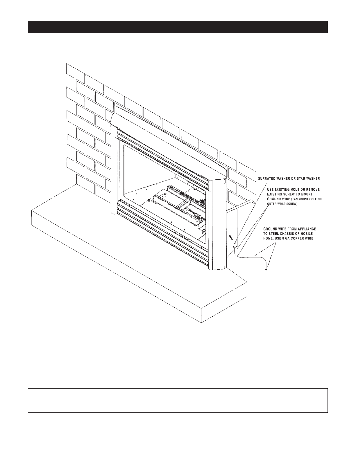
Mobile Home/Manufactured Housing Installation
This Direct Vent System Appliance must be installed in accordance with the manufacturer’s installation instructions and the Manufactured
Home Construction and Safety Standard Title 24 CFR, Part 3280, or the current Standard for Fire Safety Criteria for Manufactured Home
Installation, Sites, and Communities ANSI/NFPA 501A, and with CAN/CSA Z240 MH Mobile Home Standard in Canada.
THIS APPLIANCE MAY BE INSTALLED IN MANUFACTURED (MOBILE) HOMES AFTER FIRST SALE.
Please follow the current ANSI/NFPA 70 National Electrical Code in the USA and CAN/CSA C22.1 Canadian National Electrical Code in Canada.
An appliance must be grounded to the steel chassis of the home with 8 ga. copper wire using a serrated or star washer to penetrate paint or protective coating to insure grounding.
Use carriage bolt at the attachment point (see diagram above) to secure the appliance to the floor.
Bedroom approved.
For required venting components see venting installation in appropriate section of this manual.
Warning: Do not compromise the structural integrity of the manufactured home wall, floor or ceiling,
during installation of appliance or venting.
Page 5
5
Installation and Operation
Installation Regulations
This gas appliance must be installed by a qualified installer in accordance with local building codes, or in the absence of local codes, with
the current CAN/CGA-B149.1 or .2 Installation Code (in Canada) or
the current National Fuel Gas Code Z223.1 when installed in the
United States.
This appliance, when installed, must be electrically connected and
grounded in accordance with local codes, or in the absence of local
codes, with the current CSA C22.1 Canadian Electrical Code or with
the national Electrical Code; ANSI/NFPA 70-1987 when installed in the
United States.
FOR SAFE INSTALLATION AND OPERATION OF
YOUR GAS FIREPLACE PLEASE NOTE THE
FOLLOWING:
1. This appliance gives off high temperatures and should be located out of heavy traffic areas and away from furniture and
draperies.
2. Children and adults should be alerted to the hazards of the
high surface temperatures of this appliance and should stay
away to avoid burns or ignition of clothing.
3. Children should be carefully supervised when they are in the
same room as your fireplace appliance.
4. Under no circumstances should this appliance be modified.
Any parts that have to be removed for servicing should be
replaced prior to operating this appliance.
5. Installation and any repairs to this appliance should be done
by a qualified service person. A professional service person
should be called to inspect this appliance annually. Make it a
practice to have all your gas appliances checked annually.
6. Control compartments, burners and air passages in this appliance should be kept clean and free of dust and lint. Make sure
that the gas valve and pilot light are turned off before you
attempt to clean this unit.
7. The venting system (chimney) of this appliance should be
inspected at least once a year and if needed, your venting system should be cleaned.
8. Clothing or other flammable material should not be placed on
or near the appliance. This appliance should not be used as a
drying rack for clothing nor should Christmas stockings or
decorations be hung from it.
9. Under no circumstances should any solid fuels (wood, paper)
be used in this appliance.
10. For safe operation, glass doors must be closed.
11. Do not use this heater if any part has been under water.
Immediately call a qualified service technician to inspect the
heater and to replace any part of the control system and any
gas control which has been under water.
12. Do not operate appliance unless completely installed as per
installation instructions.
Operating and Maintenance Instructions
This gas appliance should be installed by a qualified installer in accordance with local building codes and with current CAN/CGA - B149
(.1 or .2) installation codes for Gas Burning Appliances and Equipment.
For safe installation and operation
note the following:
Never use your gas fireplace as a cooking device.
The Burner/Log Assembly has been engineered and permanently
adjusted for proper flame control.
Periodically remove the logs from the grate assembly and vacuum any loose particles from the grate and burner areas. See Log
Placement page 19 to remove logs. Vacuum burner parts and
replace logs.
Note: It is normal for your gas fireplace to give off some odor the
first time it is burned. This is due to the curing of the paint and any
undetected oil from the manufacturing process.
Please ensure that your room is well ventilated - open all windows.
It is recommended that you burn your gas fireplace for at least four (4)
hours the first time you use it without the fan on.
Warning: When purging the gas line, the glass front must be
removed.
Do not alter gas orifice.
WARNING: The front of the fireplace gives off high temperatures that could ignite combustible material which is
kept close to the front of the unit.
Certified for installation in a bedroom or bedsitting room. In Canada must be installed with listed milli volt thermostat. In USA see local codes.
WARNING: Do not operate appliance with the glass front removed, cracked or broken. Replacement of the glass
should be done by a licensed or qualified service person .
Vertical Venting in Cold Climates
In cold climate conditions where temperatures go below -10 degrees Celsius or 14
degrees Fahrenheit, we recommend that the chase be insulated and where the vent
pipe enters into the attic space that the pipe be wrapped with an insulated mylar
sleeve. This will increase the temperature of the vent and help the appliance to vent
properly in cold weather conditions.
It is also important in vertical vented direct vent appliances that the appliance be
operated daily during the winter months as this will help stop the Termination from
freezing up. We recommend using a thermostat set at room temperature to allow the
unit to cycle.
NOTE: It is recommended that a Carbon Monoxide (CO) Detector be installed in or near bedrooms and on all levels of
your home. Place a detector about 15 feet (4.5 meters) outside the room that houses your gas appliance.
Page 6
6
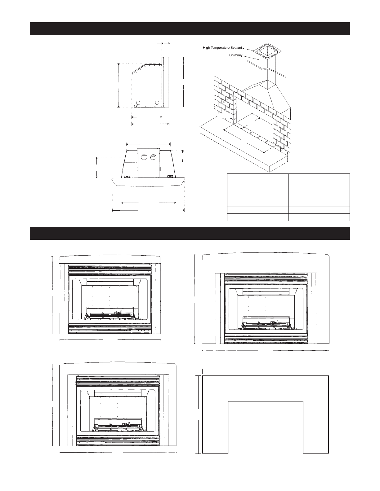
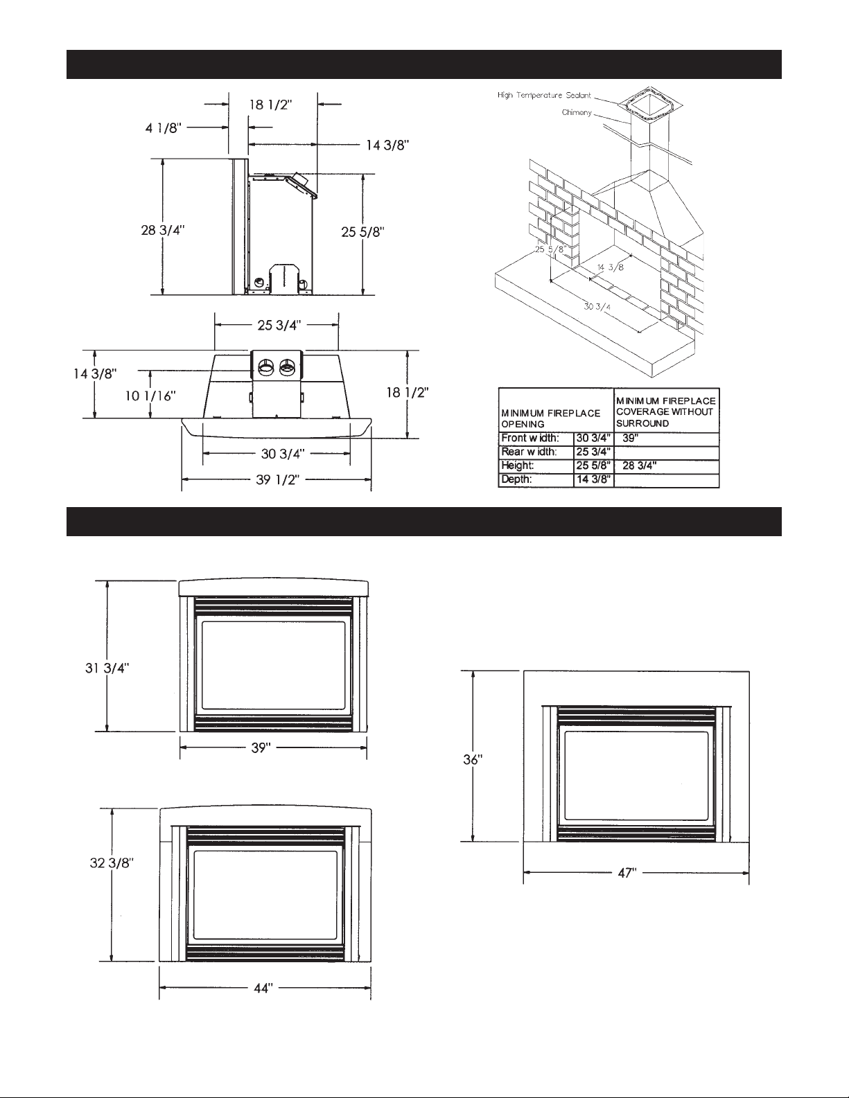
IDV33 Insert Dimension and Sizing
IDV 33 Optional Surround Sizes
I33S3426B Top Only
I33S4028B Top/Sides
I33S4535B
I33S4430B Top/Sides
4”
21
1
/4”
143/8”
18
1
/2”
24
5
/16”
211/8”
10
1
/16”
53/4”
26
1
/4”
34
1
/2”
21
3
/8”
26
1
/4”
14
3
/8”
MINIMUM FIREPLACE
COVERAGE WITHOUT
SURROUND
341/2”
241/4”
MINIMUM FIREPLACE
OPENING
Front width: 261/4”
Rear width: 211/8”
Height: 213/8”
Depth: 143/8”
45”
35”
265/8”
341/2”
301/2”
44”
28”
40”
(1 Pce.)
Page 7
77
IDV36 Insert Dimension and Sizing
IDV36 Optional Surround Sizes
I36S3931B Top Only
I36S4736B 1 Piece
I36S4432B 3 Piece Top/Sides
Page 8
88
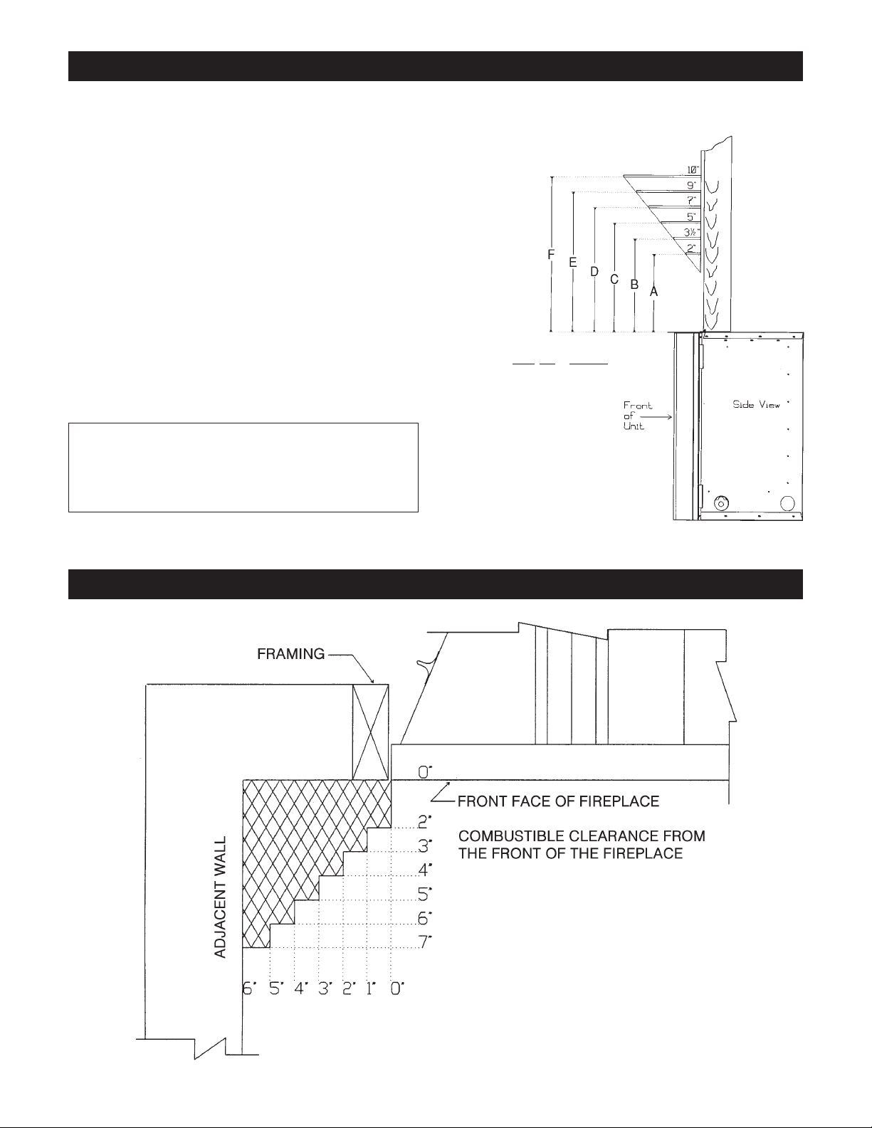
Mantels
Depending on the width of the fireplace mantel, it may be installed
higher of lower from the top of the fireplace opening. See drawings for
proper installation height of your combustible mantel. Non-combustible
mantels may be installed at any height above the fireplace opening.
Non combustible materials such as brick, tile, etc. can extend up to the
front face of the fireplace (NO PORTION OF GRILLAREA OR
DOOR AREAS CAN BE COVERED).
Note: When using paint or lacquer to finish the mantel, such paint
or lacquer must be heat resistant (250˚F) to prevent discoloration.
Warning: Combustible objects must not be placed on a non-
combustible mantel unless the non-combustible mantel
meets the minimum height and width requirements for a
combustible mantel.
Mantel Leg Clearances
Mantels
Clearance to Combustible Mantels
IDV
33 IDV36
A 10” 11”
B 12” 13”
C 14” 15”
D 16” 17”
E 18” 19”
F 20” 21”
Page 9
9
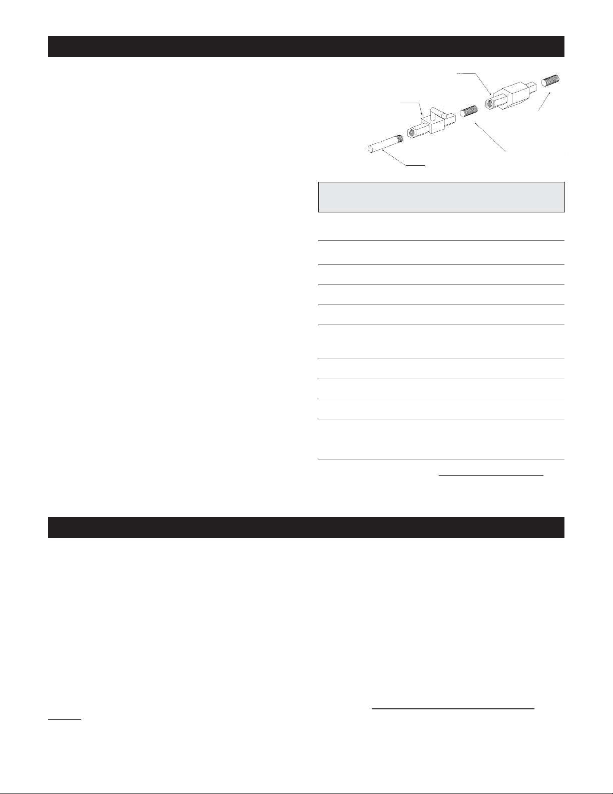
Gas Line Installation
This gas appliance should be installed by a qualified installer in accordance with
local building codes and with current CAN/CGA - B149.1 or .2 installation codes for
Gas Burning appliances and equipment in Canada and the National Fuel Gas Code
ANSI Z223 in the U.S.A.
1. The gas pipeline can be brought in through either the right or the left side of the
appliance. A knockout is provided at either location to allow for the gas pipe
installation and testing of any gas connection.
2. The gas control inlet is 3/8” NPT. Typical installation layout for rigid pipe is
shown at right.
3. When using copper or flex connector, use only approved fittings. Always
provide a union so that gas line can be easily disconnected for burner or fan
servicing. See gas specification for pressure details and ratings.
4. When a vertical section of gas pipe is required for the installation, a condensation trap is needed. See CAN/CGA-B149.1 or .2 for code details.
5. For natural gas, a minimum of 3/8” iron pipe with gas minimum pressure of 4.5
w.c. must be used for supply from the gas meter. Consult with the local gas
utility if any questions arise concerning pipe sizes.
6. A 1/8” NPT plugged tappings are accessible for test gauge connection both on
the inlet and outlet of the gas valve.
7. Turn the gas supply ON and check for leaks. DO NOT USE OPEN FLAME
FOR THIS PURPOSE. Use an approved leak testing solution.
8. The appliance and its individual shutoff valve must be disconnected from the gas
supply piping system during any pressure testing of that system at test pressures
in excess of 1/2 PSIG (3.5 KPa).
9. The appliance must be isolated from the gas supply piping system by closing its
individual shutoff valve during any pressure testing of the gas supply piping
system at test pressures equal to or less than 1/2 PSIG (3.5 KPa).
Note: The gas line connection may be made of 1/2” rigid pipe or an approved
flex connector. Since some municipalities have additional local codes, it is
always best to consult your local authorities and the current CAN/CGA - B149.1
or .2 installation code in Canada or the National Fuel Gas code ANSI Z223.1 in
the U.S.A.
Gas Specifications
Model Fuel Gas Control Maximum Input Output
IDV33N Natural Millivolt (adjustable) 31,000 BTU High 23,250
20,900 BTU Low
IDV33LP Propane Millivolt (adjustable) 28,500 BTU High 21,375
23,100 BTU Low
IDV36N Natural Millivolt (adjustable) 34,250 BTU High 25,685
24,860 BTU Low
IDV36LP Propane Millivolt (adjustable) 30,030 BTU High 22,525
22,840 BTU Low
Gas Inlet Sit or Robertshaw 3/8” NPT
Gas Supply Minimum Normal Maximum
Pressure (inches water column)
Natural Gas 4.5 7.0 9.0
Propane Gas 11.0 11.0 12.0
Manifold Natural Gas 3.5 inches water column
Pressure Propane Gas 10.5 inches water column
Orifice Size Natural Gas (0-4500 ft) IDV33N - 35 IDV36N - 32
Propane Gas (0-4500 ft) IDV33LP /IDV36LP - 51
Air Shutter NG .187 open
Openings LP .500 open
Important: Always check for gas leaks with a soap and water solution.
Do not use open flame for leak testing.
1/2” x 1/2” SHUTOFF VALVE
1/2” x 3/8” UNION
1/2” GAS SUPPLY
1/2” NIPPLE
3/8” NIPPLE
For the state of Massachusetts a T-handle gas shut-off valve must
be used on a gas appliance. This T-handle gas shut-off valve must
be listed and approved by the state of Massachusetts. This is in reference to the state of Massachusetts state code CMR238.
Venting
This appliance must not be connected to a chimney flue serving a separate solid-fuel burning appliance.
This appliance is approved with Kingsman Flex Vent System (as listed in the manual) or Simpson Duravent flex pipe system
(#0991 Co-linear Vertical Termination and #0923GK Co-linear Adapter for Termination). This fireplace insert is approved is
approved for use with two - three inch diameter gas flex liners.
All venting lining products must be approved and installed according to the vent manufacturers installation instructions. All vent
liners must terminate in a rain cap to prevent debris and rain from entering the vent and possibly damaging the appliance or creating an unsafe condition. The area between the existing chimney and liner must be capped off for the same reasons as above and
to reduce the chances of venting problems and corrosion of the vent.
If this fireplace insert is to be used to replace an existing fireplace insert the existing vent liner must be of the proper size and if so
must be inspected for obstructions, damage and/or corrosion. Replacement must be done as necessary.
Before any vent liner is run through a chimney or other approved venting system, chimne
y must be inspected, cleaned and
repaired if necessary. A chimney which was used for a solid fuel fireplace must be professionally cleaned in order to reduce corrosion of the vent or other possible safety hazards.
Page 10
10
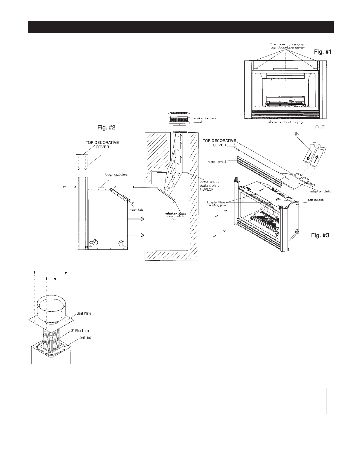
Note: Use black millpac on vent pipe joints!
1. First remove the decorative top cover (5 screws). Then simply lift upwards. (fig #1)
2. Remove adapter plate from unit by removing the two screws as shown below. (fig #3)
3. Attach the vent pipes to the termination with millpac and 4 screws per pipe joint. Be sure to
label the exhaust and intake flex pipes. Make sure not to connect the exhaust to the intake
or vice-versa. Lower the termination and vent pipe down the vent and screw and seal plate
to the chimney crown, clay tile chimney or wood stove vent. It may be necessary to pre-drill
holes into the chimney crown (depending on material) (8 screws).
4. The two vent pipes should now be hanging in the existing fireplace. Attach the adapter to the
2 suspended vent pipes with millpac and screws. Let the adapter hang in place until unit is
ready to be positioned.
5. Once the adapter is suspended by the vent pipes going up
to the termination cap slide the unit into place carefully.
(fig #2)
6. You want the adapter to
slide along the top of
the unit between
the guides making
sure it remains
flat. (fig #2)
7. Once the unit is
slid back into
position use the
2 screws
previously
removed
to secure the
adapter plate.
When tightening
the adapter plate
check to make
sure the plate is
flat to the unit
and the rear
catch lock is
engaged over
the rear tab of
unit. (fig # 2 & #3)
Venting System:
IDVVT Vertical Vent Termination
IDVFK25 Flex Pipe kit (2ea 3” x 25ft unexpanded flex pipes complete with millpac,
screws.)
#0991 Simpson Duravent Co-linear Termination HW Vertical Top
#0923GK Simpson Duravent Co-linear Adapter for Co-Liner Termination
Note: When using Simpson Duravent Termination order both #0991 and #0923GK
V
ertical (rise) Horizontal (run)
Min. 10 ft - 3.1m 0 ft - 0.0m
Max. 40 ft - 12.2m 2 ft - 0.6m
WARNING: Failure to position the parts in accordance with these diagrams or failure to use only parts specifically
approved with this appliance may result in property damage or personal injury.
INSTALLATION INSTRUCTIONS
Vertical Termination IDVVT
1. Before attaching the flex vents to the termination, you will have to determine how the cap will
be attached to the existing chimney crown, clay lined chimney or wood stove vent pipe.
The Seal Plate of the termination may be cut, notched and formed to make a good seal to the
existing vent or be left flat.
2. Using a high quality sealing compound (RTV Silicone) place a bead of sealant onto the vent or
chimney top. This will provide a seal against water and rain from entering the existing flue.
Installation of Vent Pipe
Page 11

11
THREE PIECE SURROUNDS
1. When installing 3 pc surround, install side panels first.
2. Slide side panels in place. Make sure the pre-set screws slide
into the slots located behind the side columns. Do not tighten
screws. You will need to line up the top panel first.
3. Slide top panel into place. The top panel lines up with 3 slots
behind the top grill. Secure the top panel in place with the 3
pre-set screws.
4. Once the top panel is secured, line up sides with the top and
tighten using the pre-set screws. There are two locations on
each side panel.
For installing I33S3426B or I36S3931B (1 pce surround)see step 3.
The I33S4535B and I36S4736B (1 pce surround) was designed to
be used as a custom cut out surround. Simply trace template and
cut out design using the universal surround.
Part No. Description
I33S3426B 1 pce top 34
1
/2” x 265/8”
I33S4028B 3 pce small 40” x 28”
I33S4430B 3 pc large 44” x 301/2”
I33S4535B 1 pce universal 45” x 35”
I36S3931B 1 pce top 39” x 31
3
/4”
I36S4432B 3 piece 44” x 323/8”
I36S4736B 1 pce universal 47” x 36”
* dimensions are
based on
surrounds that are
installed on unit.
IDV33 / IDV36 Insert Surround Installation
Page 12

12
IDV33 / IDV36 Riser Kit and Levelling Instructions
When installing insert it may be necessary to
support back of unit. To support back of insert,
there are two levelling plates right and left of unit.
Step 1: Measure height required to level unit.
Step 2: Remove 2 outer screws and loosen center
screw holding each plate into position.
Step 3: Slide plates to the required height and
align with appropriate holes. Each set of
holes equals to a 1/4” of movement up to
a maximum of four inches. Insert and
tighten all screws. (eg: 1” of movement
equals to 4 holes)
IDV33 / IDV36
INSERT
LEVELLING
INSTRUCTIONS
IDV33 / IDV36 INSERT RISER KIT INSTALLATION INSTRUCTIONS
MODEL No.: I33R40 / I33R44
Step 1: Measure height required to make flush with base of unit, Fig. 1. If measurement equals to the height of riser kit 2.5” skip
to Step 3. No adjustment will be required.
Step 2: Adjust levelling legs to required height in Step 1, Fig. 3 (Detail A).
Step 3: Locate mounting holes punched into base right and left of unit. Place riser assembly under front of insert and fasten to
base with supplied screws, Fig. 2.
Page 13

13
General Glass Information
Door / Door Latch Installation
Glass Cleaning
It will be necessary to clean the glass periodically. During start-up,
condensation, which is normal, forms on the inside of the glass and
causes dust, lint etc. to cling to the glass surface. Also, initial paint
curing can deposit a slight film on the glass. It is therefore recommended
that initially the glass be cleaned two or three times with non-abrasive
common household glass cleansers and warm water. After that, the glass
should be cleaned two or three times a season depending on the
circumstances.
Cautions and Warnings
• Do not clean when the glass is hot.
• The use of substitute glass will void all product warranties.
• Care must be taken to avoid breakage of the glass.
• Do not operate this fireplace without the glass front or with a broken
glass front.
• Do not strike or abuse glass.
• Do not use abrasive cleaners.
Glass Replacement
REPLACEMENT GLASS FOR BOTH DIRECT VENT UNITS
Only Robax ceramic or coated Neaoceram glass may be used for
replacement. Must be minimum 5mm thick.
Removal of the Glass Door
1. To remove, see Door/Door Latch Installation section below.
2. To replace glass, clean all materials from door frame. Using a high
heat silicone (temperature-resistant to 500°F (260°C) apply a bead
of approximately 1/32” to all four sides of frame and insert glass
with new gasket. Frame should be on flat surface, with a small
amount of weight pressing glass into silicone. Let dry approximately
15 to 20 minutes. The door can be re-installed by reversing Step 1
of Removal of Door Instructions.
REMOVAL OF DOOR:
1. Remove door by unlatching the 2 top latches. Simply place two fingers in the grooves. Pull towards yourself and lift upwards
slightly.
2. Once the top of the door is unlatched , simply pull outwards and lift upwards to unlatch the bottom.
3. When re-installing the door place bottom hooks of door in place first.
SPRING REPLACEMENT:
Over time, spring may need to be replaced if tension is lost. Replace spring as follows:
1. To remove a top latch, remove the 2 hex screws that secure it in place. They are located in the firebox.
2. To remove a bottom latch, remove the 4 hex screws located in the firebox bottom beside the burner assembly.
3. Once the screws are all removed, the latches will either fall or slide out of place.
4.
There is 1 lock nut per latch. When replacing a spring, tighten the lock nut to a total of 2.531”. This is critical for proper tension.
Page 14

14
IDV 33 Installation of Overlays
Brick Panel Installation
1. Remove door assembly,
two latch behind top
grill assembly.
2. Install rear brick panel
first.
3. Install left and right
panels and secure with
brick clip.
Page 15

15
IDV33 & IDV36 Double Door Installation
Step 1: Place Double Door over fireplace glass door and insert steel pins into latching mechanism (Ref-1)
Step 2: Slide bottom double door retainer clip down into position making sure fireplace door is between opening of retainer. (Ref-2)
IDV36 Overlay Installation
Step 1: Place Place Overlay over fireplace glass door and insert steel pins into latching mechanism. (Ref.-1 Top of Page)
Step 2: Make sure magnets are at opposite bottom corners to fasten bottom.
Page 16

16
NOTE: Make sure power supply is shut off first!
NOTE: When RE-SEALING access panel in the firebox, use
high temp. silicone/millpac.
NOTE: For fan servicing, vacuum and blow lint or dirt build
up from fan blades/motor.
1. Remove glass door assembly and log set if installed.
Be sure to handle logs carefully as they become fragile
after heated.
2. Remove back air shield by unscrewing (4 screws).
3. Remove fan access panel (15 screws). It is located on the
back and bottom right hand corner.
4. Remove the fan from the outer shell (2 hex screws). The
fan needs to be twisted and rotated slightly. The fan’s
motor end will be lifted out first.
5. Reinstall fan, bracket and all necessary components, as
shown below, once completed.
Verify proper operation after servicing.
Fan System – Access Panel/Fan Removal
Fan temperature sensor is located underneath the burner
between the valve and variable speed control. To replace,
disconnect power, remove two wires from sensor, using a
short 1/4” hex screwdriver, remove sensor, and replace.
NOTE: Make sure the wiring harness is mounted to the
bottom of insert, not touching the fire box.
WARNING
Electrical Grounding instructions
This appliance is equipped with a three prong
(grounding) plug for your protection against shock
hazard and should be plugged directly into a properly
grounded three-prong receptacle. Do not cut or remove
the grounding prong from this.
Label all wires prior to disconnecting when servicing
control. Wiring errors can cause improper and
dangerous operation.
Page 17

17
IDV33/IDV36 Insert Burner Component List
Page 18

18
1. Remove glass door assembly and logs if installed. Be careful with logs as they become fragile after being heated.
2. Lift log supports off burner assembly by lifting straight upwards.
3. The burner or burner assembly can now be removed.
A - TO REMOVE BURNER ASSEMBLY
Locate and remove the 12 screws around the outside of the burner assembly (to remove entire burner assembly).
B - TO REMOVE (H) BURNER/ORIFICE CHANGE
Remove the 2 screws holding the (H) burner in, and slide leftwards off the orifice.
4. If removing entire burner assembly, break seal and lift upwards. Make sure the gas to the unit has been disconnected.
5. To reinstall the burner assembly, use high temp millpac to seal and secure with the 12 screws.
6. Reinstall log support, logs and door.
Burner Installation/Removal
Page 19

19
MILLIVOLT SYSTEM, LIGHTING, & BURNING CONTROL
Pilot Burner Adjustment
1.Adjust pilot screw to provide
proper sized flame.
Recommended Maximum Lead Length (Double Wire)
When Using Wall Switch or Thermostat
Wire Size Max. Length
14 GA. 100 FT.
16 GA. 64 FT.
18 GA. 40 FT.
20 GA. 25 FT.
22 GA. 16 FT.
CAUTION: DO NOT
WIRE 120 VOLT
POWER TO MILLIVOLT SWITCHES OR
THERMOSTAT.
Page 20

20
LOG PLACEMENT - LOGF35
LOGF35 Log Set and Glowing Embers
Shows rear log positioning bracket and 4 pin
locating positions.
Log A has 2 locating holes, position the 2 holes
on the log over the 2 pins on the left side of the
log mounting pan as shown in the picture.
Log B has 2 locating holes, position the 2 holes
on the log over the 2 pins on the right side of
the log mounting pan as shown in the picture.
Log C has to be lowered into position just
behind logs A and B. Log C has an area
notched out of the rear of it to fit over rear
positioning bracket as shown in the picture.
A bag of Ember chunks is supplied with the log
set, it is very inportqant that these chunks are
placed onto the front burner and log mounting
pan as shown in the picture, spread the ember
chunks out no more than on Layer deep.
NOTE: IF YOU DO NOT FOLLOW THIS
INSTRUCTION CORRECTLY SOOTING
PROBLEMS CAN OCCUR.
Page 21

21
LOG PLACEMENT - LOGF36
LOGF36 Log Set and Glowing Embers, Lava
Rock and Vermiculite.
Place Log #1 onto rear log holder and center.
Place Log #2 onto left side of Log #1. Place Log
#3 onto right side of Log #1.
Locate 2 holes on bottoms of Logs #4 and 5,
position onto mounting pins.
Locate 1 hole bottom of Log #6 and place onto
pin of Log #2. Locate 2 holes bottom of Log #7
and place onto pins of Log #5.
Place Glowing Ember kit onto front Burner
Tube and Ember Plates, Lava Rock and
Vermiculite are to be place onto firebox ONLY.
Page 22

22
MQROCK1/MQRSP4 for IDV33/IDV36
MQRSP4 Parts List
1 each MQRSP4 Rock Platform
2 each Ember Plates #6000-225
1 each Ember Bridge #6000-226
1 each Support #DVI33-167
Remove the ember plates and the grate bar by removing the
2 left and right screws on the grate bar.
Reinstall screws after removing parts.
Place the MQRSP4 rock platform and ember plates
into place as shown.
Step 1: Place rocks #4 into position as shown being sure not to
place them directly over top of the burn tube.
Step 2: Place rocks #1 into position.
Step 3: Place rocks #4 into position as shown.
Page 23

23
MQROCK1/MQRSP4 for IDV33/IDV36 (continued)
Step 4: Place rocks #6 into position as shown.
Step 5: Place rocks #3 into positon as shown.
Step 6: Place rocks #1 into postion as shown.
Step 7: Place rocks #3 and #4 into position as shown.
Finished rock set and burn
Page 24

24
SECTION A
Step 1: Remove the 2 ember plates from the burner.
This step may not be required, depending on
the type of burner assembly.
Step 2: Loosen the 2 screws holding the burner in
place.
Step 3: Slide the burner to the left to expose the orifice.
Step 5: Remove the 2 screws that hold the pilot to
the bracket.
Step 6: Remove the 2 screws that attach the pilot
bracket to the firebox bottom.
Step 7: Remove the pilot bracket to expose the pilot
assembly.
Step 8: Remove the pilot tube and nut from the pilot
assembly using a 10mm wrench, slide the
tube and nut down. You may have to tap the
pilot hood lightly to release the pilot orifice.
Place new pilot orifice into the pilot assembly and reinstall the pilot tube and nut.
Tighten with wrench.
Reinstall pilot bracket at this time.
Step 9: Remove main orifice using a 1/2” wrench
and replace with new conversion orifice.
Step 10: Adjust the primary air setting to the correct
setting as specified in the manual or label
plate. To adjust the air setting, loosen the
screw on the side of the tube and rotate to
the correct opening using a drill bit or tape
measure. Retighten screw.
Reinstall burner at this time reversing STEPS
3, 2 and 1.
Step 11: Follow instructions supplied with the conver-
sion HI LOW to convert the valve from one
type of fuel to the other.
Step 12: Check for gas leaks around the pilot burner
tube and face of valve.
Step 13: Attach conversion label to label plate on bot-
tom of unit, writing information as needed.
CONVERSION KIT INSTRUCTIONS
Step 4: Before going any further you need to verify
which pilot system is in use:
– If there is a spring clip below the pilot
hood, proceed to the other side of page,
Section B, Step 5.
PLEASE CONFIRM THAT STEP 4 IS UNDERSTOOD
BEFORE PROCEEDING WITH CONVERSION.
“Warning”
This conversion kit shall be installed by a qualified service agency in accordance with the manufacturer’s
instructions and all applicable codes and requirements
of the authority having jurisdiction. If the information
in these instructions is not followed exactly, a fire,
explosion or production of carbon monoxide may
result causing property damage, personal injury or loss
of life. The qualified service agency is responsible for
the proper installation of this kit. The installation is not
proper and complete until the operation of the converted appliance is checked as specified in the manufacturer’s instructions supplied with the kit”
Page 25

25
SSSSeeeeccccttttiiiioooonnnn BB
BB
IIIInnnnssssttttaaaallllllllaaaattttiiiioooonnnn IIIInnnnssssttttrrrruuuuccccttttiiiioooonnnnss
ss
GAS CONVERSION KIT FOR TOP
CONVERTIBLE PILOT
SERIES 019065X
SIT Group
Instructions for converting SIT 190 series pilot burner injection from NG to LPG and from NG to LPG Only.
This information should be considered as supplemental to the Appliance Manufacturer’s Instructions.
WARNING!
The installation of this conversion kit must only be undertaken by a qualified
and certified gas appliance installer.
1
Shut off the gas supply to the appliance.
2
Allow the pilot burner to cool to room temperature.
WARNING: Touching a hot pilot burner can result in injury.
3
The pilot hood is held in place by spring pressure.
Remove the hood by pulling it directly up from the pilot bracket (1).
4
Insert a 5/32” or 4mm Allen wrench into the hexagonal key-way of the
injector (2), and rotate it counter clockwise until it is free of the injector
journal (3).
5
Verify that the new injector is proper for the application. The injector size
is stamped on the side of the injector near the top. LPG injectors have a
groove machined around their circumference near the top, while NG
injectors do not have a groove (5).
Refer to the Appliance Manufacturers instruction sheet for the proper
injector size.
6
Insert the Allen wrench into the end of the injector. Then, insert into injector journal, and rotate the injector clockwise until a torque of 9 in-lbs. is
achieved.
7
Replace the pilot hood by aligning the tab on the base of the hood with
the slot in the side of the pilot journal, and push the hood down, directly
onto the pilot bracket (4). The hood must sit squarely on the bracket for
proper operation. Check to insure that the hood is properly seated onto
the pilot bracket.
8
Proceed to Section A, Step 9.
WARNING!
This conversion kit must only be applied as part of a conversion kit supplied by the
appliance Manufacturer for the specific appliance, and type of gas being converted.
INSTALLER NOTICE. These instructions must be left with appliance.
Page 26
26
IDV33 Parts List
PART NO. DESCRIPTION
Fireplace Part Numbers
IDV33N INSERT DIRECT VENT
FIREPLACE (Natural Gas) 31,500 BTU
IDV33LP INSERT DIRECT VENT
FIREPLACE (Liquid Propane) 28,500 BTU
FIREPLACE REQUIREMENTS
Log Sets (Required for each unit)
LOGF35 Log Set Fibre Split Oak(350 Series)
MQROCK1 Rock Set
MQRSP4 Rock Platform, Support, Embers, Plates, Bridge
IDV33 Grills
Z6GBA Grill Kit - Classic Builder Antique Brass
Z6GBC Grill Kit - Classic Builder Chrome
Z6GBP Grill Kit - Classic Builder Polish Brass
VI30GBL Grill Kit - Black
VI30GAB Grill Kit - Antique Brass
VI30GPB Grill Kit - Polish Brass
Z6GCR Grill Kit - Chrome
VI30PBL Panel Grill Kit - Black
IDV33 Surround Kits
I33S3426B Top Piece Only
I33S4028B Top and Sides
I33S4430B Top and Sides
I33S4535B Universal For Custom Applications
Door Frames Overlays
Z33ADDX Arch Door Frame - Deluxe Black (352)
Z33ADTH Arch Door Frame - Top Half Black (353T)
Z33ADDA Arch Door Frame - Double Arch Black (354)
Z33ADDD Arch Door Frame - Double Door Arch Black (355)
Designer Doors for IDV33
Z33DDA1BL Designer Door Arch - Series 1 - Black
Z33DDTA1A Trim - Antique for Designer Arch - Series 1
Z33DDTA1C Trim - Chrome for Designer Arch - Series 1
Z33DDTA1P Trim - Polish Brass for Designer Arch - Series 1
Z33DDS1BL Designer Door Straight - Series 1 - Black
Z33DDTS1A Trim - Antique for Designer Straight - Series 1
Z33DDTS1C Trim - Chrome for Designer Straight - Series 1
Z33DDTS1P Trim - Polish for Designer Straight - Series 1
Brick Liners
IDV33RL
IDV33 Conversion Kits
33IDV-CKNG Conversion Kit Natural Gas (IDV33N) c/w Reg.
Kit NG, Pilot Orifice, Burner Orifice and
Conversion Label
33IDV-CKLP Conversion Kit - Liquid Propane (IDV33LP) c/w
Reg. Kit LP, Pilot Orifice, Burner Orifice and
Conversion Label
PART NO. DESCRIPTION
Fireplace Part Numbers
IDV36N INSERT DIRECT VENT
FIREPLACE (Natural Gas) 34,250 BTU
IDV36LP INSERT DIRECT VENT
FIREPLACE (Liquid Propane) 30,030BTU
FIREPLACE REQUIREMENTS
Log Sets (Required for each unit)
LOGF35 Log Set Fibre Split Oak
LOGF36 Log Set Fibre Split Oak
MQROCK1 Rock Set
MQRSP4 Rock Platform, Support, Embers, Plates, Bridge
IDV36 Grills
IDV36GBA Grill Kit - Classic Builder Antique Brass
IDV36GBC Grill Kit - Classic Builder Chrome
IDV36GBP Grill Kit - Classic Builder Polish Brass
IDV36GBL Grill Kit - Black
IDV36PBL Panel Grill Kit - Black
IDV36 Surround Kits
I36S3931B Top Piece Only
I36S4432B Top and Sides
I36S4736B Universal For Custom Applications
Door Frames overlays
HB36ADTH Arch Door Top Half Black
HB36ADDX Arch Door Frame - Deluxe Black
HB36ADDA Arch Door Frame - Double Arch Black
HB36ADDD Arch Door Frame - Double Door Arch Black
HB36CSS Child Safety Screen - 36” DV Fireplaces
Designer Doors for IDV36
HB36DDA1BL Designer Door Arch - Series 1 - Black
HB36DDTA1A Trim - Antique for Designer Arch - Series 1
HB36DDTA1C Trim - Chrome for Designer Arch - Series 1
HB36DDTA1P Trim - Polish Brass for Designer Arch - Series 1
HB36DDS1BL Designer Door Straight - Series 1 - Black
HB36DDTS1A Trim - Antique for Designer Straight - Series 1
HB36DDTS1C Trim - Chrome for Designer Straight - Series 1
HB36DDTS1P Trim - Polish for Designer Straight - Series 1
Brick Liners
IDV36RLT Traditional
IDV36RLH Herring Bone
IDV36 Conversion Kits
36IDV-CKNG Conversion Kit Natural Gas (IDV36N) c/w Reg.
Kit NG, Pilot Orifice, Burner Orifice and
Conversion Label
36IDV-CKLP Conversion Kit - Liquid Propane (IDV36LP) c/w
Reg. Kit LP, Pilot Orifice, Burner Orifice and
Conversion Label
IDV36 Parts List
Fireplace Accessories IDV33
Fireplace Accessories IDV36
Conversion Kits IDV33
Conversion Kits IDV36
Page 27

27
PART NO. DESCRIPTION
Riser Kits
I33R40 2 1/2” Riser for use with I33S4028B and
I36S3931B
I33R44 2
1
/2” Riser for use with I33S4430B and
I36S4432B
Other Accessories
Z1MT Thermostat Millivolt Wall Mount
Z80PT Thermostat Programmable Digital Millivolt
Wall Mount (1F80-40)
Z1RC Remote Control Millivolt (On/Off with LED)
(Model I)
ZART Remote Control Thermostat Millivolt (Model K)
RMCBN Remote Control - Basic - Natural Gas
(On/Off, Hi/Lo Flame Adjustment, Millivolt Only)
RMCBP Remote Control - Basic - Liquid Propane
(On/Off, Hi/Lo Flame Adjustment, Millivolt Only)
DCHS Remote Control Heatshield
Replacement Burner Assembly / Burner
33IDV-BNGSI BURNER ASSEMBLY (NG) - C/W VALVE
SYSTEM For use on IDV33N only
33IDV-BLPSI BURNER ASSEMBLY (LP) - C/W VALVE
SYSTEM For use on IDV33LP and IDV36LP
36IDV-BNGSI BURNER ASSEMBLY (NG) - C/W VALVE
SYSTEM For use on IDV36N only
33IDV-200A H BURNER only For use on IDV33/IDV36
PART NO. DESCRIPTION
Miscellaneous Parts
1000-150 GE #SILICONE GE RED IS806 #736
1000-150 MP #HI-TEMP MILL PAC SEALANT 840099
1000-214 #PIEZO-IGNITOR 1244-17 MARK 21
1000-215 #PAL NUT (18MMXI.5MM)BLK (1364.03)
1000-255 #ORIFICE BRASS - # 37 Natural Gas
1000-255 #ORIFICE BRASS - # 57 Liquid Propane
350-EMBER #EMBERS
2000-P5637 #SPRING EXTENSION FOR GRILLS
6000-150 #CERAMIC ROBAX GLASS 27.5 X 16 ID33
36HB-310 CERAMIC GLASS FOR IDV36
36IDV-MAN #MANUAL - IDV33/IDV36
2000-080 #THERMODISC 2450 (For Blower)
2000-081 #BLOWER MOTOR QLN65/2400
2000-085 #CONTROL VARIABLE SPEED KBWC-13BV
33IDV-123 #REPLACEMENT SPRING FOR DOOR LATCH
33IDV-106A #ADAPTER PLATE COMPLETE
IDVVT Vertical Termination - Co-linear 3”/3”
IDVFK25 2 ea. 3” dia. Unexpanded 25 ft. Flex Pipe,
screws/washers, Millpac
IDVLCP Lower Chase Sealant Plate
ZDV3FC Flex Connectors 3” Diameter
Parts for IDV33 and IDV36 Parts for IDV33 and IDV36
Parts for IDV33 and IDV36 Venting
Page 28

28
Trouble Shooting The Gas Control System
WARNING: BEFORE DOING ANY GAS CONTROL SERVICE WORK, REMOVE THE GLASS FRONT.
NOTE: Before troubleshooting the gas control system, be sure external gas shut off is in the “On” position.
Problem Possible Causes Corrective Action
Spark igniter will not light. Defective or misaligned electrode Check for spark at electrode and pilot: if no spark and electrode wire is
at pilot. properly connected, replace igniter.
Defective igniter Using a match, light pilot. If pilot lights, turn off pilot and push the red
(push-button) button again. If pilot will not light - check gap at electrode and pilot
should be 1/8” to 1/4” to have a strong spark.
Pilot will not stay lit after carefully Defective thermocouple Check pilot flame. Must impinge on generator and thermocouple.
following lighting instructions. (flame switch where applicable) Clean and/or adjust pilot for maximum flame impingement on
generator and thermocouple. Replace thermocouple if pilot will not
hold. (Hand tight 1/8 turn on replacement)
Defective valve magnet. Replace valve, if pilot won’t hold after the thermocouple is replaced.
Pilot burning, no gas to burner, Wall switch or wires Check wall switch and wires for proper connections. Jumper wire
Valve knob “ON”, Wall defective. across terminals at wall switch. If burner comes on, replace defective
Switch “ON” wall switch. If okay, jumper wires, across wall switch wires at valve.
If burner comes on, wires are faulty or connections are bad.
Generator may not be generating Check generator with millivolt meter. Take reading at generator termisufficient voltage. nals of gas valve. Should read 325 millivolts minimum while holding
valve knob depressed in pilot position and wall switch “off” Replace
faulty generator if reading is below specified minimum.
Plugged burner orifice. Check burner orifice for stoppage and remove.
Defective automatic valve Remove wall switch wires from gas valve. Install jumper wires from
operator. top bottom terminals of gas valve. Turn valve on “ON”. If main burner
does not light, replace valve.
Frequent Pilot outage problem. Pilot flame may be too low or Clean and/or adjust pilot flame for maximum flame impingement
blowing (high) causing the pilot on generator and thermocouple.
safety to drop out.
Flame lifts off burner and goes out 3” liner has come off flue Attach 3” liner to flue or termination using
in less than 30 seconds or termination, flame is starving screws, silicone and clamps as stated in manual
for oxygen
Flame lifts off burner on Improper installation of firebrick. Be sure to position firebrick against firebox walls and
one side while the rest of Firebrick is likely leaning. be sure to use brick clips attached to the inner side
the flame remains lit. of firebox.
Page 29

14
BASIC ONE YEAR WARRANTY
During the first year after installation, we will provide a replacement for any component part of your unit found to be defective in materials
or workmanship, including labour costs. Repair work requires prior approval by Kingsman, labour costs are based on a predetermined rate
schedule and any repair work must be done through an authorized Kingsman dealer.
LIMITED LIFETIME WARRANTY
The heat exchanger, combustion chamber and burner of every Kingsman product excluding the Outdoor Firepit are warranted against
materials or workmanship during the period the product is owned by the original owner. The part to be replaced must be returned to our
distributor in exchange for the replacement part. Any labor, material, freight and/or handling charges associated with any repair
or replacement pursuant to this Limited Lifetime Warranty will not be covered by this warranty.
GENERAL TERMS
In lieu of providing a replacement part, we may, at our option, provide the distributor's component purchase price from us or a credit equal
to the distributors component purchase price from us toward the purchase of any new unit which we distribute. If a credit is given
in lieu of a replacement part, the rating plate from the unit being replaced must be submitted on a warranty claim, and the unit being
replaced must be made available to our distributor for disposition.
In establishing the date of installation for any purpose, including determination of the starting date for the term of this Limited Lifetime
Warranty, reasonable proof of the original installation date must be presented*, otherwise the effective date will be based upon the date of
manufacture plus thirty (30) days.
We will not be responsible for and you, the user, will pay for: (a) damages caused by accident, abuse, negligence, misuse, riot, fire, flood,
or Acts of God (b) damages caused by operating the unit where there is a corrosive atmosphere containing chlorine, fluorine, or any other
damaging chemicals (other than in a normal residential environment) (c) damages caused by any unauthorized alteration or repair
of the unit affecting its stability or performance (d) damages caused by improper matching or application of the unit or the unit's components
(e) damages caused by failing to provide proper maintenance and service to the unit (f) any expenses incurred for erecting, disconnecting
or dismantling the unit (g) parts or supplies used in connection with service or maintenance (h) damage repairs, inoperation or inefficiency
resulting from faulty installation or application (i) electricity or fuel costs or any increase in electricity or fuel cost whatsoever including
additional or unusual use of supplemental electric heat.
We shall not be liable for any incidental, consequential, or special damages or expenses in connection with any use or failure of this unit.
We have not made and do not make any representation or warranty of fitness for a particular use or purpose, and there is no implied condition
of fitness for a particular use or purpose. We make no express warranties except as stated in this Limited Lifetime Warranty. No one is authorized
to change this Limited Lifetime Warranty or to create for us any other obligation or liability in connections with this unit. Any implied
warranties shall last for one year after the original installation. Some states and provinces do not allow the exclusion or limitation of incidental
or consequential damages or do not allow limitations on how long an implied warranty or condition lasts, so the above limitations or exclusions may not apply to you. The provisions of this limited warranty are in additions to and not a modification of or subtraction from any statutory warranties and other rights and remedies provided by law.
Save this certificate. It gives you specific legal rights, and you may also have other rights which may vary from state to state and province to province.
In the event your unit needs servicing, contact your dealer or contractor who installed or serviced your unit. When requesting service,
please have the model and serial number from each unit readily available. If your dealer needs assistance, the distributor is available for support
and we, in turn support the distributor's efforts.
Fill in the installation date and model and serial numbers of the unit in the space provided below and retain this limited warranty for your files.
Model No. Serial No. Date installed
Dealer or Contractor Name :
*
To receive advantage of your warranty, you must retain the original records that can establish the installation date of your unit.
LIMITED LIFETIME WARRANTY
This Limited Lifetime Warranty applies only while the unit remains at the site of the original
installation and only if the unit is installed inside the continental United States, Alaska, Hawaii,
and Canada. The warranty applies only if the unit is installed and operated in accordance
with the printed instructions and in compliance with applicable installation and building codes
and good trade practices.
The Ultimate in Design, Engineering & Quality
 Loading...