

Kingsman HBZDV4224, HBZDV4232, HBZDV4228 Installation Instructions Manual
Installation Instructions
Listed Certified for USA. and Canada
Model Numbers HBZDV4224, HBZDV4228, HBZDV4232
Stock #’s: HBZDV4224N, HBZDV4224LP
are Certified to:ANSI Z21.50a-2000, CSA 2.22a-2000,
CGA 2.17-M91
, CSA P.4.1-02
Stock #’s: HBZDV4228N, HBZDV4228LP, HBZDV4232N and HBZDV4232LP
are Certified to:ANSI Z21.88b-2003, CSA-2.33b-2003, CGA 2.17-M91, CSA P.4.1-02
KINGSMAN INDUSTRIES
A Division of R-Co. Inc.
2340 Logan Avenue
Winnipeg, Manitoba, Canada R2R 2V3
Ph: (204) 632-1962
Printed in Canada 06/05/30 Part # 42HB-MAN
This appliance may be installed in an aftermarket permanently located, manufactured home (USA only)
or mobile home, where not prohibited by local codes.
This appliance is only for use with the type of gas indicated on the rating plate. This appliance is not
convertible for use with other gases, unless a certified kit is used.
Read this complete manual before beginning installation.
These instructions must be kept with the unit for future reference.
FOR Y OUR SAFETY
Warning: Improper installation, adjustment, alteration, service or maintenance
can cause property damage, personal injury or loss of life. Refer to this manual.
Installation and service must be performed by a qualified installer, service
agency or the gas supplier.
Do not store or use gasoline or other flammable vapors and liquids in the
vicinity of this or any other appliance.
W
hat To Do If You Smell Gas
Do not try to light any appliance.
Extinguish any open flame.
Do not touch any electrical switch.
Do not use any phone in your building.
Immediately call your gas supplier from a neighbour’s phone.
If you can not reach your gas supplier, call the fire department.
WARNING: If the information in these instructions are not followed exactly, a fire
or explosion may result causing property damage, personal injury or loss of life.
“Zero Clearance”
Direct Vent Gas Fireplace

2
Why does my fireplace or stove give off odor?
It is normal for your fireplace to give off some odor. This is due to the curing of the paint, adhesives,
silicones and any undetected oil from the manufacturing process as well as the finishing materials used
with the installations (e.g. marble, tile and the adhesives used to adhere this product to the walls can
react with heat and cause odors).
It is recommended that you burn your gas fireplace or stove for a minimum of four hours at a time with
the fan off after the curing of the paint has been completed. These odors can last upward to 40 hours
of burn time, keep burning at a minimum of four hours per use until odors dissipate.
About curing of the paint
Your stove or fireplace has been painted with the highest quality silicone stove paint. This paint dries
quickly in 15-20 minutes when first applied at the factory. However, due to the high temperature silicone components, the paint will cure when heat is applied to the appliance as it is first used.
The following information applies to the curing process to get the paint fully hard and durable.
Fire the appliance four successive times for 10 minutes each firing and a 5 minute cool down between
each. Be aware during log and firebox paint curing that a white deposit may be developing on the
inside of the glass doors. It is important to remove this white deposit from the glass doors with an
appropriate cleaner to prevent build-up (such as Windex or a commercial fireplace glass cleaner).
• Babies, small children, pregnant women and pets should leave the area during the cure phase.
• Ventilate well, open doors and windows.
• Do not touch during curing.
Noise coming from the fireplace?
• Noise caused by metal expanding and contracting as it heats up and cools down, similar to the
sound produced by a furnace or heating duct. This noise does not affect the operation or longevity of your fireplace.
PRE-INSTALLATION QUESTIONS and ANSWERS
Mobile Home/Manufactured Housing Installation . . . . . . . .4
Installation and operation . . . . . . . . . . . . . . . . . . . . . . . . . . . .5
Locating your appliance . . . . . . . . . . . . . . . . . . . . . . . . . . . . .6
Fireplace Dimensions . . . . . . . . . . . . . . . . . . . . . . . . . . . . . . .6
Framing your gas fireplace . . . . . . . . . . . . . . . . . . . . . . . . . . .7
Installing Clean View Kit (CVCK) . . . . . . . . . . . . . . . . . . . . .8
Clearances to Combustibles, Mantels and Surrounds . . .8 & 9
Gas Line Installation . . . . . . . . . . . . . . . . . . . . . . . . . . . . . . .10
Fan kit installation . . . . . . . . . . . . . . . . . . . . . . . . . . . . . . . . .11
Removing burner system/Access Cover . . . . . . . . . . . . . . . .12
Millivolt system, lighting, & burner control . . . . . . . . . . . . .13
Brick Installation . . . . . . . . . . . . . . . . . . . . . . . . . . . . . . . . . .14
Door and glass information . . . . . . . . . . . . . . . . . . . . . . . . . .15
Log Reference Chart . . . . . . . . . . . . . . . . . . . . . . . . . . . . . . .15
Log Placement Guide . . . . . . . . . . . . . . . . . . . . . . . . . . .16-21
Vent termination . . . . . . . . . . . . . . . . . . . . . . . . . . . . . . . . . .22
Venting graph . . . . . . . . . . . . . . . . . . . . . . . . . . . . . . . . . . . .23
General vent installation information . . . . . . . . . . . . . . . . . .24
Installation of side wall venting . . . . . . . . . . . . . . . . . . . . . .24
Venting vertical . . . . . . . . . . . . . . . . . . . . . . . . . . . . . . . . . . .25
Conversion kit . . . . . . . . . . . . . . . . . . . . . . . . . . . . . . . . . . . .26
Kingsman Fireplace part numbers . . . . . . . . . . . . . . . . . . . .28
Kingsman Log Sets Required . . . . . . . . . . . . . . . . . . . . . . . .28
Kingsman Fireplace Accessories Options . . . . . . . . . . . . . . .28
Kingsman Fireplace Designer Doors . . . . . . . . . . . . . . . . . .28
Kingsman Burner Assembly and Valve system parts . . . . . .28
Kingsman Miscellaneous parts and Conversion Kits . . . . . .29
Kingsman Fireplace Venting . . . . . . . . . . . . . . . . . . . . . . . . .30
Trouble shooting the gas control system . . . . . . . . . . . . . . . .30
Kingsman Industries Gas Fireplace – Limited Warranty . . .31
Table of Contents
4
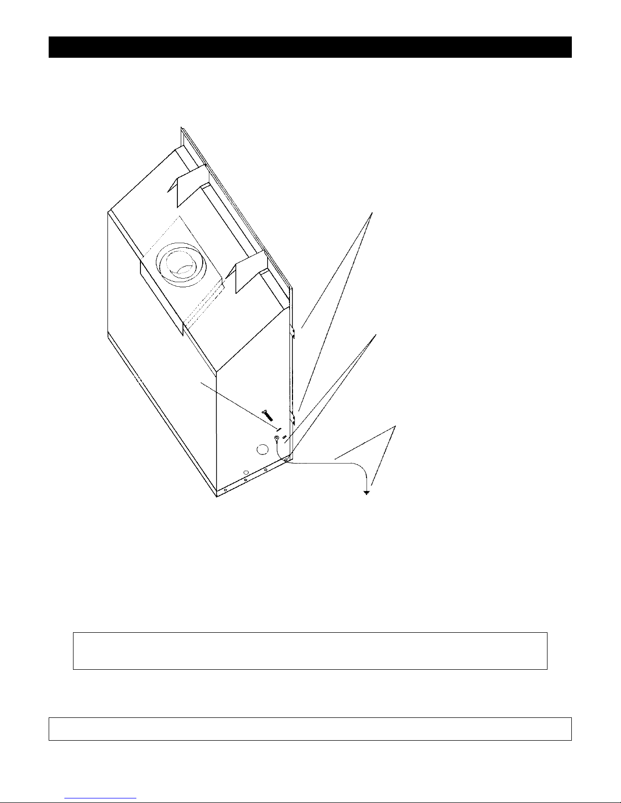
Mobile Home/Manufactured Housing Installation
This Direct Vent System Appliance must be installed in accordance with the manufacturer’s installation instructions and the Manufactured Home
Construction and Safety Standard Title 24 CFR, Part 3280, or the current Standard for Fire Safety Criteria for Manufactured Home Installations, Sites,
and Communities ANSI/NFPA 501A, and with CAN/CSA Z240 MH Mobile Home Standard in Canada.
THE HBZDV4228N, HBZDV4228LP, HBZDV4232N and HBZDV4232LP MAY BE INSTALLED IN MANUFACTURED (MOBILE)
HOMES AFTER FIRST SALE IN THE USA. IN CANADA THE HBZDV4228N, HBZDV4228LP, HBZDV4232N AND HBZDV4232LP
MAY BE INSTALLED IN MANUFACTURED (MOBILE) HOMES.
Please follow the current ANSI/NFPA 70 National Electrical Code in the USA and CAN/CSA C22.1 Canadian National Electrical Code in Canada.
An appliance must be grounded to the steel chassis of the home with 8 ga. copper wire using a serrated or star washer to penetrate paint or protective
coating to insure grounding.
Use carriage bolt at the attachment point (see diagram above) to secure the appliance to the floor.
Warning: Do not compromise the structural integrity of the manufactured home wall, floor or
ceiling, during installation of appliance or venting.
For required venting components see venting installation in appropriate section of this manual.
Certified for installation in a bedroom or bedsitting room. In Canada must be installed with listed milli volt thermostat. In USA see local codes.
APPLIANCE MUST BE SECURED TO STRUCTURE
USING SUPPLIED NAIL TABS AND OR FASTEN TO
FLOOR
USE EXISTING HOLE OR REMOVE
EXISTING SCREW TO MOUNT GROUND
WIRE
(FAN MOUNT HOLE OR OUTER WRAP SCREW)
GROUND WIRE FROM APPLIANCE
TO STEEL CHASSIS OF MOBILE
HOME. USE 8 GA COPPER WIRE.
SERRATED OR
STAR WASHER
5
Installation and Operation
Installation Regulations
This gas appliance must be installed by a qualified installer in
accordance with local building codes, or in the absence of local
codes, with the current CAN/CGA-B149.1 or .2 Installation Code
(in Canada) or the current National Fuel Gas Code Z223.1 when
installed in the United States.
This appliance, when installed, must be electrically connected and
grounded in accordance with local codes, or in the absence of local
codes, with the current CSA C22.1 Canadian Electrical Code or
with the national Electrical Code; ANSI/NFPA 70-1987 when
installed in the United States.
FOR SAFE INSTALLATION AND OPERATION OF
YOUR GAS FIREPLACE PLEASE NOTE THE
FOLLOWING:
1. This appliance gives off high temperatures and should be
located out of heavy traffic areas and away from furniture
and draperies.
2. Children and adults should be alerted to the hazards of the
high surface temperatures of this appliance and should stay
away to avoid burns or ignition of clothing.
3. Children should be carefully supervised when they are in
the same room as your fireplace appliance.
4. Under no circumstances should this appliance be modified.
Any parts that have to be removed for servicing should be
replaced prior to operating this appliance.
5. Installation and repair should be done by a qualified service
person. The appliance should be inspected before use and
at least annually by a professional service person. More frequent cleaning may be required due to excessive lint from
carpeting, bedding material, et cetera. It is imperative that
control compartments, burners and circulating air passageways of the appliance be kept clean.
6. Control compartments, burners and air passages in this
appliance should be kept clean and free of dust and lint.
Make sure that the gas valve and pilot light are turned off
before you attempt to clean this unit.
7. The venting system (chimney) of this appliance should be
inspected at least once a year and if needed, your venting
system should be cleaned.
8. Clothing or other flammable material should not be placed
on or near the appliance. This appliance should not be used
as a drying rack for clothing nor should Christmas stockings or decorations be hung from it.
9. Under no circumstances should any solid fuels (wood,
paper) be used in this appliance.
10. For safe operation, glass doors must be closed.
11. Do not use this heater if any part has been under water.
Immediately call a qualified service technician to inspect the
heater and to replace any part of the control system and any
gas control which has been under water.
12. WARNING: Do not operate appliance with the glass front
removed, cracked or broken. Replacement of glass should
be done by a licensed or qualified service person.
13. Do not operate appliance unless completely installed as per
installation instructions.
14. In the Commonwealth of Massachusetts a CO detector must
be installed in the same room as the appliance.
Never use your gas fireplace as a cooking device.
The Burner/Log Assembly has been engineered and permanently
adjusted for proper flame control.
Periodically remove the logs from the grate assembly and vacuum
any loose particles from the grate and burner areas.
See log Placement on Pages 16-21 to remove logs, vacuum burner
parts and replace logs.
Note: It is normal for your gas fireplace to give off some odor
the first time it is burned. This is due to the curing of the paint
and any undetected oil from the manufacturing process.
Please ensure that your room is well ventilated - open all windows.
It is recommended that you burn your gas fireplace for at least four
(4) hours the first time you use it without the fan on.
Make adequate accessibility clearances for servicing and proper
operation.
This appliance must not be connected to a chimney flue serving a
separate solid fuel burning appliance.
Be sure that the flow of combustion and ventilation air is not
obstructed.
Warning: When purging the gas line, the glass front must be
removed.
Do not alter gas orifice.
Vertical Venting in Cold Climates
In cold climate conditions where temperatures go below -10 degrees
Celsius or 14 degrees Fahrenheit, we recommend that the chase be insulated and where the vent pipe enters into the attic space that the pipe be
wrapped with an insulated mylar sleeve. This will increase the temperature of the vent and help the appliance to vent properly in cold weather
conditions.
It is also important in vertical vented direct vent appliances that the appliance be operated daily during the winter months as this will help stop the
Termination from freezing up. We recommend using a thermostat set at
room temperature to allow the unit to cycle.
NOTE: It is recommended that a Carbon Monoxide (CO)
Detector be installed in or near bedrooms and on all levels of your
home. Place a detector about 15 feet (4.5 meters) outside the room
that houses your gas appliance.
6
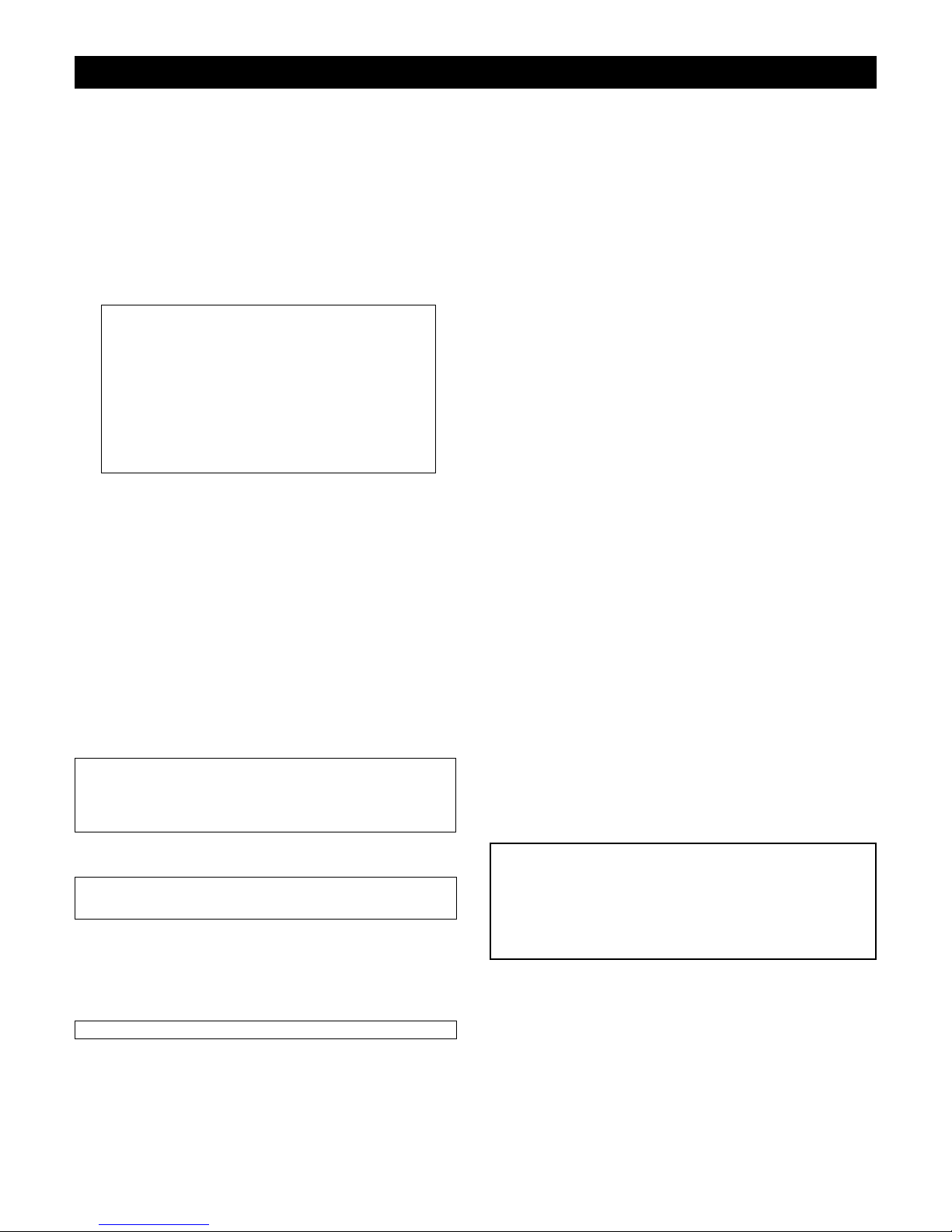
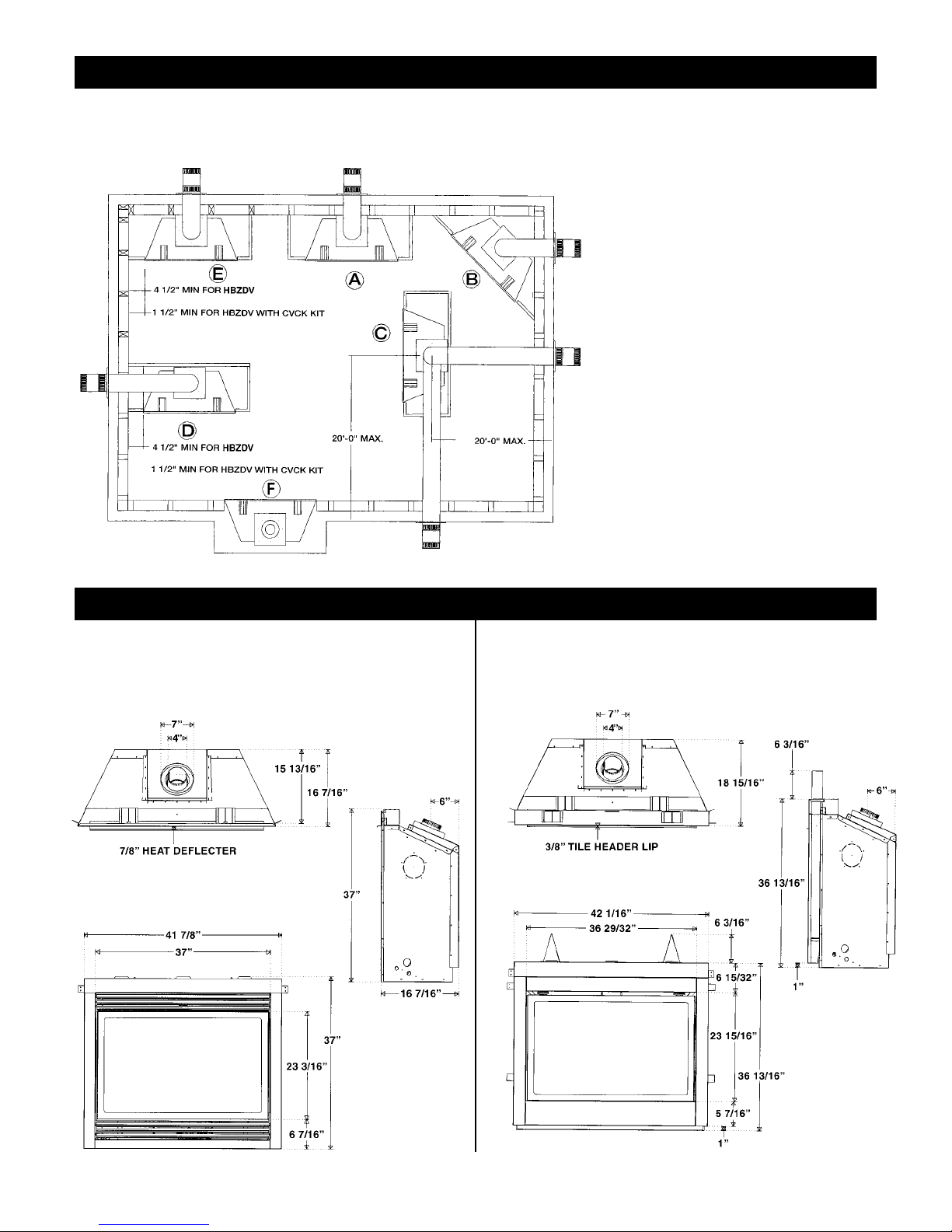
Locating your Appliance
Fireplace Dimensions
(above or below grade)
Installing with Top Vent
Island installation with a top vent is possible as long
as the horizontal portion of the vent system does
not exceed 20 feet (6.1 m).
A - Flat on a wall D - As a room divider
B - Across the corner E - Flat on wall corner
C - As an island F - Exterior wall
HBZDV42 -CVCK (Clean View Circulating Kit)
HBZDV42 louvered
7
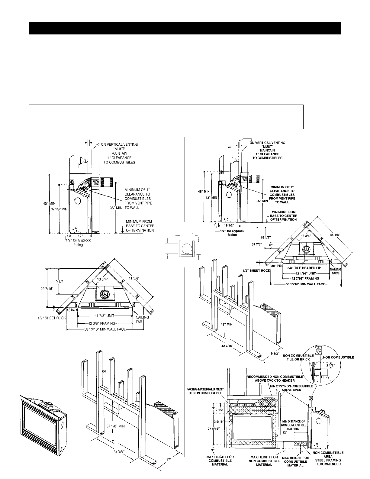
Framing for your Gas Fireplace
Framing Specifications
1. Cold climate installation recommendation: When installing this fireplace
against non insulated exterior wall or chase, it is recommended that the
outer walls be insulated to conform to applicable insulation codes. Drywall
must be installed over insulation to prevent contact of insulation and unit.
2. Choose fireplace location and frame in accordance with the fireplace
framing dimensions specified (See Framing Diagrams). Bend nailing tabs
forward on left and right of unit and place fireplace into framed enclosure.
This allows for 1/2” in front of framing tabs for finishing materials.
HBZDV42 louvered
HBZDV42 WITH CVCK (CLEAN VIEW CIRCULATING KIT)
3. Drywall or other material can extend flush with the appliance on the
bottom, sides and top of fireplace. (louvered models only)
4. When installing horizontal with a 90 degree bend maintain a minimum of
two and a half (2.5”) inches above the bend in enclosures.
5.
For HBZDV with louvers combustible floor can raise 1” above the
bottom of the fireplace. For HBZDV with CVCK (Clean view
Circulating Kit) floor or hearth can raise 7” above the bottom of the
fireplace with portions being combustible and non combustible. See
drawing Below.
It is recommended for Propane Horizontal Installations that the venting should be a minimum of one foot vertical off the
flue before the elbow on any horizontal runs of one foot or greater. This allows for cleaner combustion and greatly reduces
carboning and cleaning of glass. (Does not apply to Back Flue Models).
TOP VIEW
11"
11"
821⁄32" DIA.
8
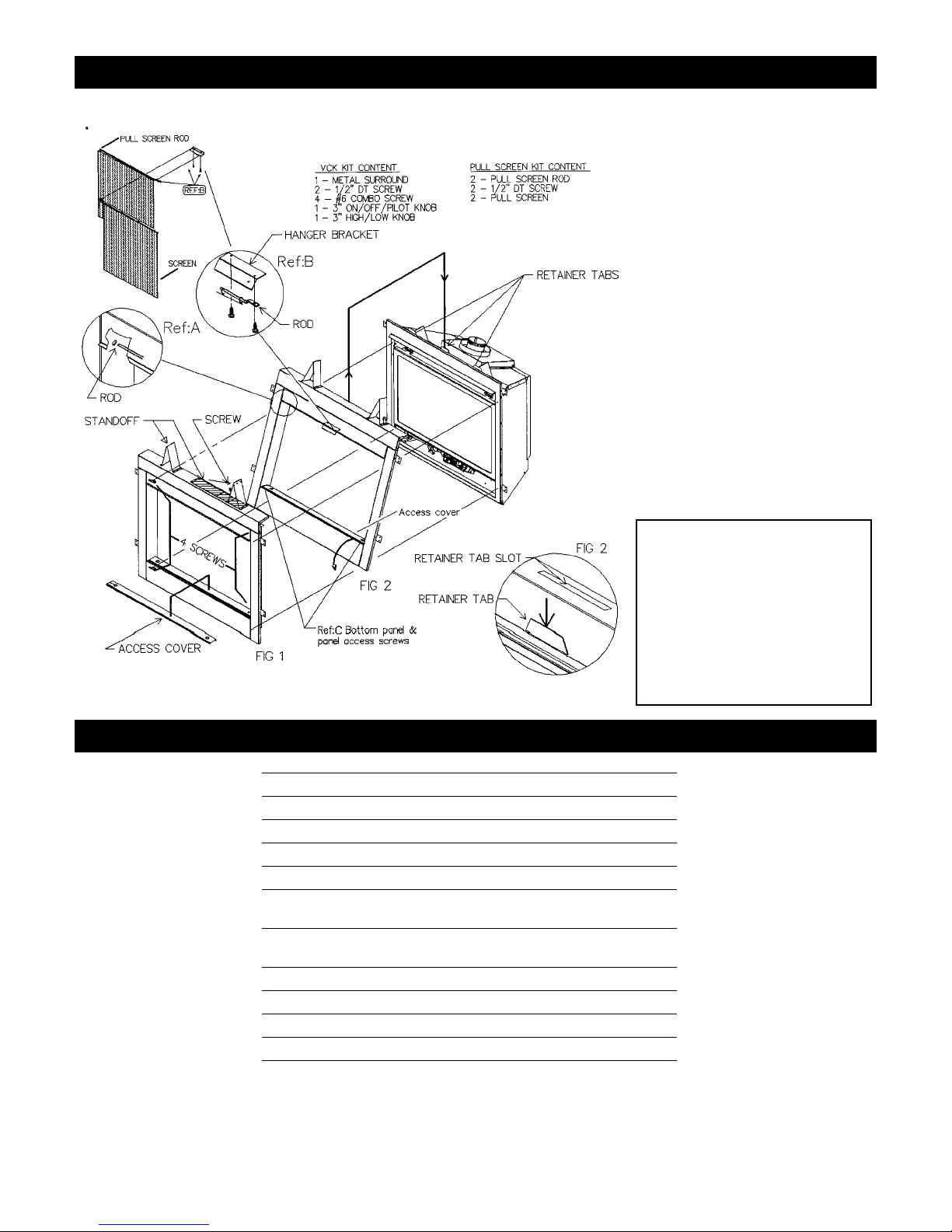
HOW TO INSTALL CLEAN VIEW KIT (CVCK)
Clearance to Combustibles
Clearance to Combustibles
Back (from Standoffs) 0 inches/0 mm
Side (from standoffs) 0 inches/0 mm
Floor 0 inches/0 mm
Ceiling (from bottom of fireplace) 60 inches/150 cm
Top (from standoffs) 0 inches/0 mm
Top of 90 degree bend in Minimum
Enclosure of 45 to 46 inches 5 inches/128 mm / Kingsman Vent Systems
Top of 90 degree bend in
Enclosure over 46 inches 21/2 inches/64 mm / Kingsman Vent Systems
Top of Horizontal Pipe 11/2 inches/38 mm / Kingsman Vent Systems
Side & Bottom of Horizontal Pipe 1 inch/25.5mm / Kingsman Vent Systems
Vertical Vent Pipe 1 inch/25.5mm / Kingsman Vent Systems
Vertical Vent Pipe 11/4 inch/32mm / Simpson Duravent Systems
(NOTE -Floor) if installing the appliance directly on carpeting or other
combustible materials other than wood flooring, the appliance shall be
installed on a metal or wood panel, the full width and depth of the appliance.
Carpet may extend 1 inch above the floor of appliance.
For units with CVCK (Clear View Circulating Kit) see framing with CVCK
to establish floor heights
CAUTION:
When using CVCK
DO NOT INSTALL
a Louver assembly
1. Install optional Fan Kit (See Fan Instruction)
2. Fold two standoffs up into position & mount
with supplied Screws. (Fig. 1)
3. Hang CVCK on top of fireplace retainer tabs
and rotate down into position. (Fig. 2)
4. Using four supplied #6 screws fasten CVCK kit
to the inside frame of unit.
5. Kit is supplied with 2 valve extension knobs
align notches and slide onto valve.
6. *Do not brick or tile beyond inside area of
CVCK kit to allow for removal of door.
7. Install optional pull screen system: First slide
curtain onto rods and slide round end of rod
into side post Ref: A, using 1/2” DTscrews
mount flattened end of rod to bottom side of
rod hanger bracket Ref: B, repeat this step for
opposite side.
Note:Additional Access for gasline
installation and Fan Electrical
installation.When CVCK kit is
installed in framing remove 2
screws from the right and left side
of bottom panel Ref: C. Once
screws are removed, bottom panel
can be rotated forward for access
to gas valve and fan system.
9
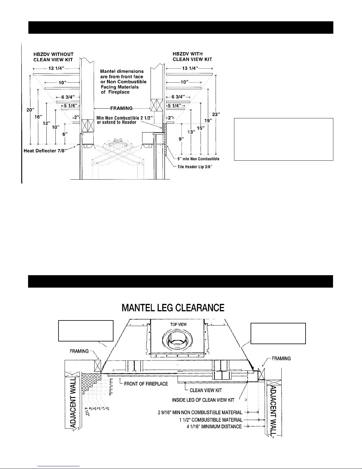
Mantels
Depending on the depth of the fireplace mantel, it may be installed higher or lower from the top of the fireplace opening. See drawings for proper
installation height of your combustible mantel. Non-combustible mantels may be installed at any height above the fireplace opening.
Non combustible materials such as brick, tile, etc. can extend up to or over the front face of the fireplace (NO PORTION OF GRILLAREA OR
DOOR AREAS CAN BE COVERED) except where designer clean view kit is used.
Combustible material can extend flush to unit up to the top, bottom and sides of fireplace to stand-offs.
For COMBUSTIBLE materials extending in front of fireplace consult (Mantel and Mantel Leg Drawings).
Surrounds
If installing wide or slim line surrounds, the finish materials must be flush with the front facing of the fireplace. See page 6, the floor should be built
up 1” in front of the fireplace in order for the surrounds to sit flush to the floor.
Note: When using paint or lacquer to finish the mantel, such paint or lacquer must be heat resistant (250˚F) to prevent discoloration.
Warning: Combustible objects must not be
placed on a non-combustible mantel unless
the non-combustible mantel meets the
minimum height and width requirements for
a combustible mantel.
Mantel Leg Clearances
Mantels & Surrounds
HBZDV with
Louvers
HBZDV with
Clean View Kit
10
Gas Line Installation
This gas appliance should be installed by a qualified installer in accordance with local
building codes and with current CAN/CGA - B149.1 or .2 installation codes for Gas
Burning appliances and equipment in Canada and the National Fuel Gas Code ANSI
Z223 in the U.S.A.
1. The gas pipeline can be brought in through either the right or the left side of the appliance. Aknockout is provided at either location to allow for the gas pipe installation and
testing of any gas connection.
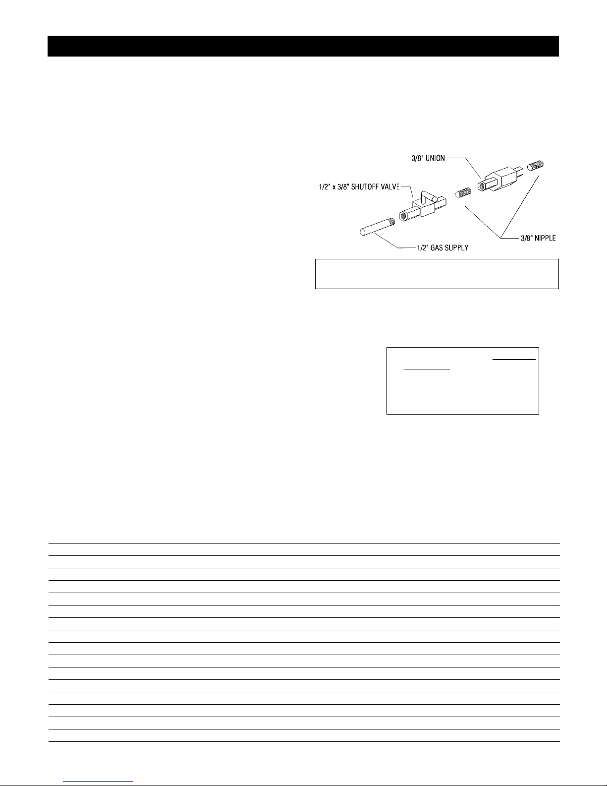
2. The gas control inlet is 3/8” NPT. Typical installation layout for rigid pipe is shown at
right.
3. When using copper or flex connector, use only approved fittings. Always provide a
union so that gas line can be easily disconnected for burner or fan servicing. See gas
specification for pressure details and ratings.
4. When a vertical section of gas pipe is required for the installation, a condensation trap is
needed. See CAN/CGA-B149.1 or .2 for code details.
5. For natural gas, a minimum of 3/8” iron pipe with gas minimum pressure of 4.5” w.c.
must be used for supply from the gas meter. Consult with the local gas utility if any questions arise concerning pipe sizes.
6. A 1/8” NPT plugged tappings are accessible for test gauge connection both on the inlet
and outlet of the gas valve.
7. Turn the gas supply ON and check for leaks. DO NOT USE OPEN FLAME FOR THIS
PURPOSE. Use an approved leak testing solution.
8. The appliance and its individual shutoff valve must be disconnected from the gas supply
piping system during any pressure testing of that system at test pressures in excess of 1/2
PSIG (3.5 KPa).
9. The appliance must be isolated from the gas supply piping system by closing its individual shutoff valve during any pressure testing of the gas supply piping system at test pressures equal to or less than 1/2 PSIG (3.5 KPa).
Note: The gas line connection may be made of 1/2” rigid pipe or an
approved flex connector. Since some municipalities have additional local
codes, it is always best to consult your local authorities and the current
CAN/CGA - B149.1 or .2 installation code in Canada or the National Fuel
Gas code ANSI Z223.1 in the U.S.A.
Gas Specifications
Top Flue Top Flue
Models HBZDV4224N HBZDV4224LP HBZDV4228N HBZDV4228LP HBZDV4232N HBZDV4232LP
Fuel Natural Propane Natural Propane Natural Propane
Gas Control Millivolt adjustable Millivolt adjustable Millivolt adjustable Millivolt adjustable Millivolt adjustable Millivolt adjustable
Maximum 24,000 BTU High 22,000 BTU High 28,000 BTU High 26,000 BTU High 30,500 BTU High 29,200 BTU High
Input 14,000 BTU Low 15,000 BTU Low 20,000 BTU Low 19,000 BTU Low 20,600 BTU Low 22,200 BTU Low
Maximum n/a n/a 21,000 BTU 19,500 BTU 22,900 BTU 21,900 BTU
Output
Orifice Size #42 #53 #37 #52 #36 #51
(0 - 4500 ft)
Air Shutter .125” – 1/8” Fully Open .218” – 7/32” Fully Open .187” – 3/16” .312” – 5/16”
Gas Inlet Size S.I.T. 820 Nova, 3/8” NPT
Gas Supply Pressure Minimum Normal Maximum
Natural Gas 5.5” 7” 9”
Liquid Propane 11” 11” 12”
Manifold Pressure Natural Gas Liquid Propane
Manifold Pressure High 3.5 IN. W.C./.87 KPa 10 IN. W.C./2.61 KPa
Manifold Pressure Low 1.6 IN. W.C./.40 KPa 6.3 IN. W.C./1.57 KPa
Important: Always check for gas leaks with a soap and water
solution. Do not use open flame for leak testing.
For the state of Massachusetts a T-handle gas
shut-of
f valve
must be used on a gas
appliance. This T-handle gas shut-off valve
must be listed and approved by the state of
Massachusetts. This is in reference to the state
of Massachusetts state code CMR238.
 Loading...