

Page 1
Installation Instructions
Listed Certified for USA. and Canada
Model Numbers HBZDV4224, HBZDV4228, HBZDV4232
Stock #’s: HBZDV4224N, HBZDV4224LP
are Certified to:ANSI Z21.50a-2000, CSA 2.22a-2000,
CGA 2.17-M91
, CSA P.4.1-02
Stock #’s: HBZDV4228N, HBZDV4228LP, HBZDV4232N and HBZDV4232LP
are Certified to:ANSI Z21.88b-2003, CSA-2.33b-2003, CGA 2.17-M91, CSA P.4.1-02
KINGSMAN INDUSTRIES
A Division of R-Co. Inc.
2340 Logan Avenue
Winnipeg, Manitoba, Canada R2R 2V3
Ph: (204) 632-1962
Printed in Canada 06/05/30 Part # 42HB-MAN
This appliance may be installed in an aftermarket permanently located, manufactured home (USA only)
or mobile home, where not prohibited by local codes.
This appliance is only for use with the type of gas indicated on the rating plate. This appliance is not
convertible for use with other gases, unless a certified kit is used.
Read this complete manual before beginning installation.
These instructions must be kept with the unit for future reference.
FOR Y OUR SAFETY
Warning: Improper installation, adjustment, alteration, service or maintenance
can cause property damage, personal injury or loss of life. Refer to this manual.
Installation and service must be performed by a qualified installer, service
agency or the gas supplier.
Do not store or use gasoline or other flammable vapors and liquids in the
vicinity of this or any other appliance.
W
hat To Do If You Smell Gas
Do not try to light any appliance.
Extinguish any open flame.
Do not touch any electrical switch.
Do not use any phone in your building.
Immediately call your gas supplier from a neighbour’s phone.
If you can not reach your gas supplier, call the fire department.
WARNING: If the information in these instructions are not followed exactly, a fire
or explosion may result causing property damage, personal injury or loss of life.
“Zero Clearance”
Direct Vent Gas Fireplace
Page 2

2
Why does my fireplace or stove give off odor?
It is normal for your fireplace to give off some odor. This is due to the curing of the paint, adhesives,
silicones and any undetected oil from the manufacturing process as well as the finishing materials used
with the installations (e.g. marble, tile and the adhesives used to adhere this product to the walls can
react with heat and cause odors).
It is recommended that you burn your gas fireplace or stove for a minimum of four hours at a time with
the fan off after the curing of the paint has been completed. These odors can last upward to 40 hours
of burn time, keep burning at a minimum of four hours per use until odors dissipate.
About curing of the paint
Your stove or fireplace has been painted with the highest quality silicone stove paint. This paint dries
quickly in 15-20 minutes when first applied at the factory. However, due to the high temperature silicone components, the paint will cure when heat is applied to the appliance as it is first used.
The following information applies to the curing process to get the paint fully hard and durable.
Fire the appliance four successive times for 10 minutes each firing and a 5 minute cool down between
each. Be aware during log and firebox paint curing that a white deposit may be developing on the
inside of the glass doors. It is important to remove this white deposit from the glass doors with an
appropriate cleaner to prevent build-up (such as Windex or a commercial fireplace glass cleaner).
• Babies, small children, pregnant women and pets should leave the area during the cure phase.
• Ventilate well, open doors and windows.
• Do not touch during curing.
Noise coming from the fireplace?
• Noise caused by metal expanding and contracting as it heats up and cools down, similar to the
sound produced by a furnace or heating duct. This noise does not affect the operation or longevity of your fireplace.
PRE-INSTALLATION QUESTIONS and ANSWERS
Page 3

Mobile Home/Manufactured Housing Installation . . . . . . . .4
Installation and operation . . . . . . . . . . . . . . . . . . . . . . . . . . . .5
Locating your appliance . . . . . . . . . . . . . . . . . . . . . . . . . . . . .6
Fireplace Dimensions . . . . . . . . . . . . . . . . . . . . . . . . . . . . . . .6
Framing your gas fireplace . . . . . . . . . . . . . . . . . . . . . . . . . . .7
Installing Clean View Kit (CVCK) . . . . . . . . . . . . . . . . . . . . .8
Clearances to Combustibles, Mantels and Surrounds . . .8 & 9
Gas Line Installation . . . . . . . . . . . . . . . . . . . . . . . . . . . . . . .10
Fan kit installation . . . . . . . . . . . . . . . . . . . . . . . . . . . . . . . . .11
Removing burner system/Access Cover . . . . . . . . . . . . . . . .12
Millivolt system, lighting, & burner control . . . . . . . . . . . . .13
Brick Installation . . . . . . . . . . . . . . . . . . . . . . . . . . . . . . . . . .14
Door and glass information . . . . . . . . . . . . . . . . . . . . . . . . . .15
Log Reference Chart . . . . . . . . . . . . . . . . . . . . . . . . . . . . . . .15
Log Placement Guide . . . . . . . . . . . . . . . . . . . . . . . . . . .16-21
Vent termination . . . . . . . . . . . . . . . . . . . . . . . . . . . . . . . . . .22
Venting graph . . . . . . . . . . . . . . . . . . . . . . . . . . . . . . . . . . . .23
General vent installation information . . . . . . . . . . . . . . . . . .24
Installation of side wall venting . . . . . . . . . . . . . . . . . . . . . .24
Venting vertical . . . . . . . . . . . . . . . . . . . . . . . . . . . . . . . . . . .25
Conversion kit . . . . . . . . . . . . . . . . . . . . . . . . . . . . . . . . . . . .26
Kingsman Fireplace part numbers . . . . . . . . . . . . . . . . . . . .28
Kingsman Log Sets Required . . . . . . . . . . . . . . . . . . . . . . . .28
Kingsman Fireplace Accessories Options . . . . . . . . . . . . . . .28
Kingsman Fireplace Designer Doors . . . . . . . . . . . . . . . . . .28
Kingsman Burner Assembly and Valve system parts . . . . . .28
Kingsman Miscellaneous parts and Conversion Kits . . . . . .29
Kingsman Fireplace Venting . . . . . . . . . . . . . . . . . . . . . . . . .30
Trouble shooting the gas control system . . . . . . . . . . . . . . . .30
Kingsman Industries Gas Fireplace – Limited Warranty . . .31
Table of Contents
Page 4
4
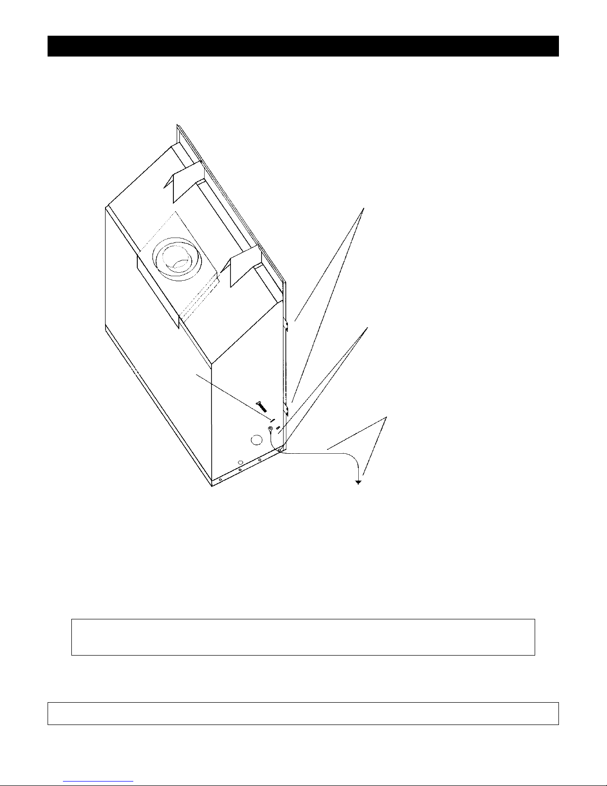
Mobile Home/Manufactured Housing Installation
This Direct Vent System Appliance must be installed in accordance with the manufacturer’s installation instructions and the Manufactured Home
Construction and Safety Standard Title 24 CFR, Part 3280, or the current Standard for Fire Safety Criteria for Manufactured Home Installations, Sites,
and Communities ANSI/NFPA 501A, and with CAN/CSA Z240 MH Mobile Home Standard in Canada.
THE HBZDV4228N, HBZDV4228LP, HBZDV4232N and HBZDV4232LP MAY BE INSTALLED IN MANUFACTURED (MOBILE)
HOMES AFTER FIRST SALE IN THE USA. IN CANADA THE HBZDV4228N, HBZDV4228LP, HBZDV4232N AND HBZDV4232LP
MAY BE INSTALLED IN MANUFACTURED (MOBILE) HOMES.
Please follow the current ANSI/NFPA 70 National Electrical Code in the USA and CAN/CSA C22.1 Canadian National Electrical Code in Canada.
An appliance must be grounded to the steel chassis of the home with 8 ga. copper wire using a serrated or star washer to penetrate paint or protective
coating to insure grounding.
Use carriage bolt at the attachment point (see diagram above) to secure the appliance to the floor.
Warning: Do not compromise the structural integrity of the manufactured home wall, floor or
ceiling, during installation of appliance or venting.
For required venting components see venting installation in appropriate section of this manual.
Certified for installation in a bedroom or bedsitting room. In Canada must be installed with listed milli volt thermostat. In USA see local codes.
APPLIANCE MUST BE SECURED TO STRUCTURE
USING SUPPLIED NAIL TABS AND OR FASTEN TO
FLOOR
USE EXISTING HOLE OR REMOVE
EXISTING SCREW TO MOUNT GROUND
WIRE
(FAN MOUNT HOLE OR OUTER WRAP SCREW)
GROUND WIRE FROM APPLIANCE
TO STEEL CHASSIS OF MOBILE
HOME. USE 8 GA COPPER WIRE.
SERRATED OR
STAR WASHER
Page 5
5
Installation and Operation
Installation Regulations
This gas appliance must be installed by a qualified installer in
accordance with local building codes, or in the absence of local
codes, with the current CAN/CGA-B149.1 or .2 Installation Code
(in Canada) or the current National Fuel Gas Code Z223.1 when
installed in the United States.
This appliance, when installed, must be electrically connected and
grounded in accordance with local codes, or in the absence of local
codes, with the current CSA C22.1 Canadian Electrical Code or
with the national Electrical Code; ANSI/NFPA 70-1987 when
installed in the United States.
FOR SAFE INSTALLATION AND OPERATION OF
YOUR GAS FIREPLACE PLEASE NOTE THE
FOLLOWING:
1. This appliance gives off high temperatures and should be
located out of heavy traffic areas and away from furniture
and draperies.
2. Children and adults should be alerted to the hazards of the
high surface temperatures of this appliance and should stay
away to avoid burns or ignition of clothing.
3. Children should be carefully supervised when they are in
the same room as your fireplace appliance.
4. Under no circumstances should this appliance be modified.
Any parts that have to be removed for servicing should be
replaced prior to operating this appliance.
5. Installation and repair should be done by a qualified service
person. The appliance should be inspected before use and
at least annually by a professional service person. More frequent cleaning may be required due to excessive lint from
carpeting, bedding material, et cetera. It is imperative that
control compartments, burners and circulating air passageways of the appliance be kept clean.
6. Control compartments, burners and air passages in this
appliance should be kept clean and free of dust and lint.
Make sure that the gas valve and pilot light are turned off
before you attempt to clean this unit.
7. The venting system (chimney) of this appliance should be
inspected at least once a year and if needed, your venting
system should be cleaned.
8. Clothing or other flammable material should not be placed
on or near the appliance. This appliance should not be used
as a drying rack for clothing nor should Christmas stockings or decorations be hung from it.
9. Under no circumstances should any solid fuels (wood,
paper) be used in this appliance.
10. For safe operation, glass doors must be closed.
11. Do not use this heater if any part has been under water.
Immediately call a qualified service technician to inspect the
heater and to replace any part of the control system and any
gas control which has been under water.
12. WARNING: Do not operate appliance with the glass front
removed, cracked or broken. Replacement of glass should
be done by a licensed or qualified service person.
13. Do not operate appliance unless completely installed as per
installation instructions.
14. In the Commonwealth of Massachusetts a CO detector must
be installed in the same room as the appliance.
Never use your gas fireplace as a cooking device.
The Burner/Log Assembly has been engineered and permanently
adjusted for proper flame control.
Periodically remove the logs from the grate assembly and vacuum
any loose particles from the grate and burner areas.
See log Placement on Pages 16-21 to remove logs, vacuum burner
parts and replace logs.
Note: It is normal for your gas fireplace to give off some odor
the first time it is burned. This is due to the curing of the paint
and any undetected oil from the manufacturing process.
Please ensure that your room is well ventilated - open all windows.
It is recommended that you burn your gas fireplace for at least four
(4) hours the first time you use it without the fan on.
Make adequate accessibility clearances for servicing and proper
operation.
This appliance must not be connected to a chimney flue serving a
separate solid fuel burning appliance.
Be sure that the flow of combustion and ventilation air is not
obstructed.
Warning: When purging the gas line, the glass front must be
removed.
Do not alter gas orifice.
Vertical Venting in Cold Climates
In cold climate conditions where temperatures go below -10 degrees
Celsius or 14 degrees Fahrenheit, we recommend that the chase be insulated and where the vent pipe enters into the attic space that the pipe be
wrapped with an insulated mylar sleeve. This will increase the temperature of the vent and help the appliance to vent properly in cold weather
conditions.
It is also important in vertical vented direct vent appliances that the appliance be operated daily during the winter months as this will help stop the
Termination from freezing up. We recommend using a thermostat set at
room temperature to allow the unit to cycle.
NOTE: It is recommended that a Carbon Monoxide (CO)
Detector be installed in or near bedrooms and on all levels of your
home. Place a detector about 15 feet (4.5 meters) outside the room
that houses your gas appliance.
Page 6
6
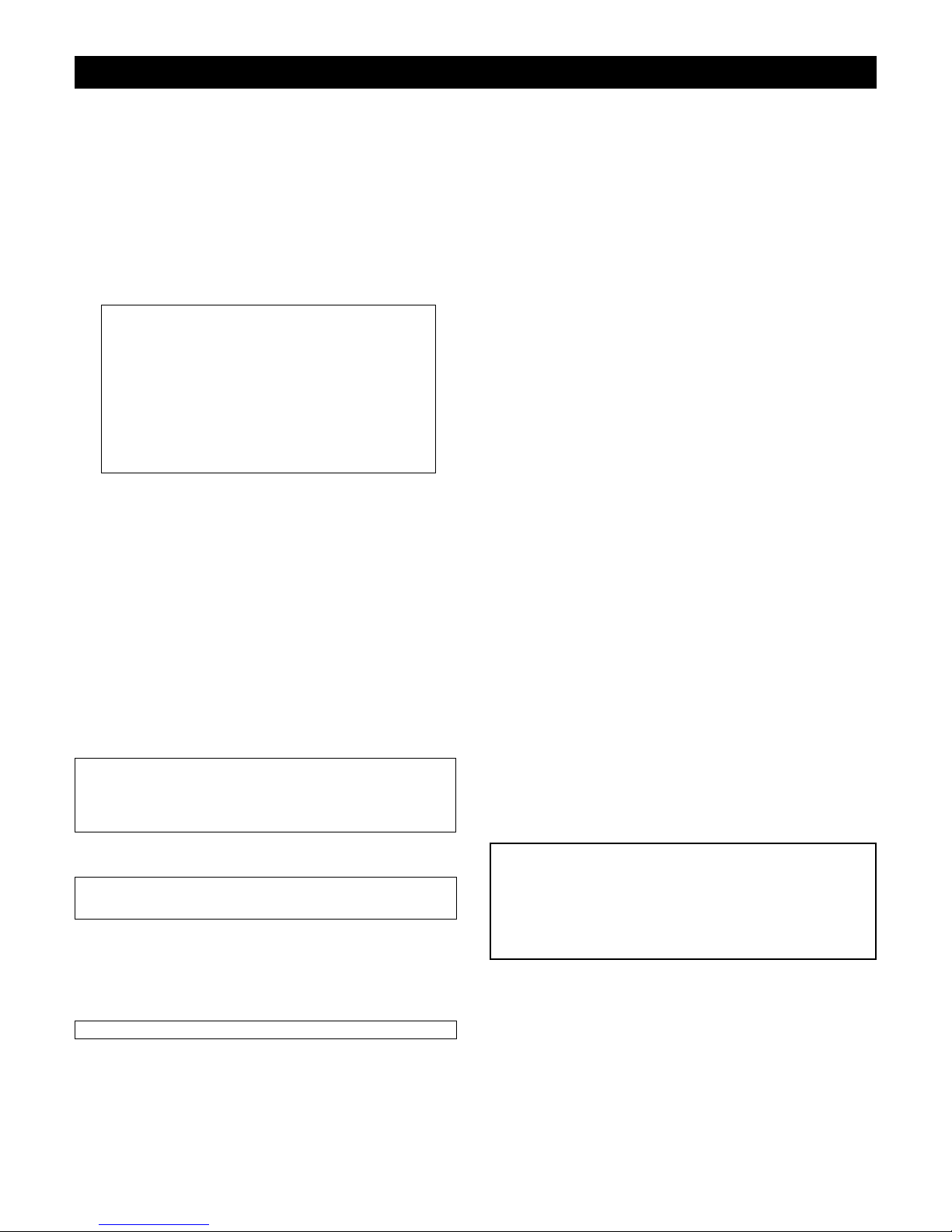
Locating your Appliance
Fireplace Dimensions
(above or below grade)
Installing with Top Vent
Island installation with a top vent is possible as long
as the horizontal portion of the vent system does
not exceed 20 feet (6.1 m).
A - Flat on a wall D - As a room divider
B - Across the corner E - Flat on wall corner
C - As an island F - Exterior wall
HBZDV42 -CVCK (Clean View Circulating Kit)
HBZDV42 louvered
Page 7
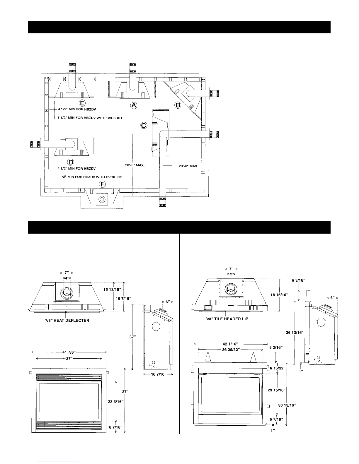
7
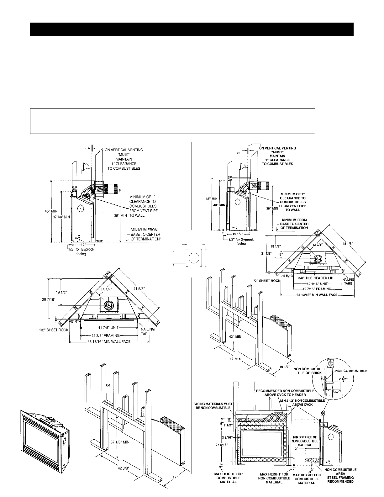
Framing for your Gas Fireplace
Framing Specifications
1. Cold climate installation recommendation: When installing this fireplace
against non insulated exterior wall or chase, it is recommended that the
outer walls be insulated to conform to applicable insulation codes. Drywall
must be installed over insulation to prevent contact of insulation and unit.
2. Choose fireplace location and frame in accordance with the fireplace
framing dimensions specified (See Framing Diagrams). Bend nailing tabs
forward on left and right of unit and place fireplace into framed enclosure.
This allows for 1/2” in front of framing tabs for finishing materials.
HBZDV42 louvered
HBZDV42 WITH CVCK (CLEAN VIEW CIRCULATING KIT)
3. Drywall or other material can extend flush with the appliance on the
bottom, sides and top of fireplace. (louvered models only)
4. When installing horizontal with a 90 degree bend maintain a minimum of
two and a half (2.5”) inches above the bend in enclosures.
5.
For HBZDV with louvers combustible floor can raise 1” above the
bottom of the fireplace. For HBZDV with CVCK (Clean view
Circulating Kit) floor or hearth can raise 7” above the bottom of the
fireplace with portions being combustible and non combustible. See
drawing Below.
It is recommended for Propane Horizontal Installations that the venting should be a minimum of one foot vertical off the
flue before the elbow on any horizontal runs of one foot or greater. This allows for cleaner combustion and greatly reduces
carboning and cleaning of glass. (Does not apply to Back Flue Models).
TOP VIEW
11"
11"
821⁄32" DIA.
Page 8
8
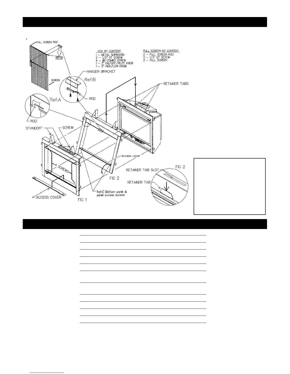
HOW TO INSTALL CLEAN VIEW KIT (CVCK)
Clearance to Combustibles
Clearance to Combustibles
Back (from Standoffs) 0 inches/0 mm
Side (from standoffs) 0 inches/0 mm
Floor 0 inches/0 mm
Ceiling (from bottom of fireplace) 60 inches/150 cm
Top (from standoffs) 0 inches/0 mm
Top of 90 degree bend in Minimum
Enclosure of 45 to 46 inches 5 inches/128 mm / Kingsman Vent Systems
Top of 90 degree bend in
Enclosure over 46 inches 21/2 inches/64 mm / Kingsman Vent Systems
Top of Horizontal Pipe 11/2 inches/38 mm / Kingsman Vent Systems
Side & Bottom of Horizontal Pipe 1 inch/25.5mm / Kingsman Vent Systems
Vertical Vent Pipe 1 inch/25.5mm / Kingsman Vent Systems
Vertical Vent Pipe 11/4 inch/32mm / Simpson Duravent Systems
(NOTE -Floor) if installing the appliance directly on carpeting or other
combustible materials other than wood flooring, the appliance shall be
installed on a metal or wood panel, the full width and depth of the appliance.
Carpet may extend 1 inch above the floor of appliance.
For units with CVCK (Clear View Circulating Kit) see framing with CVCK
to establish floor heights
CAUTION:
When using CVCK
DO NOT INSTALL
a Louver assembly
1. Install optional Fan Kit (See Fan Instruction)
2. Fold two standoffs up into position & mount
with supplied Screws. (Fig. 1)
3. Hang CVCK on top of fireplace retainer tabs
and rotate down into position. (Fig. 2)
4. Using four supplied #6 screws fasten CVCK kit
to the inside frame of unit.
5. Kit is supplied with 2 valve extension knobs
align notches and slide onto valve.
6. *Do not brick or tile beyond inside area of
CVCK kit to allow for removal of door.
7. Install optional pull screen system: First slide
curtain onto rods and slide round end of rod
into side post Ref: A, using 1/2” DTscrews
mount flattened end of rod to bottom side of
rod hanger bracket Ref: B, repeat this step for
opposite side.
Note:Additional Access for gasline
installation and Fan Electrical
installation.When CVCK kit is
installed in framing remove 2
screws from the right and left side
of bottom panel Ref: C. Once
screws are removed, bottom panel
can be rotated forward for access
to gas valve and fan system.
Page 9
9
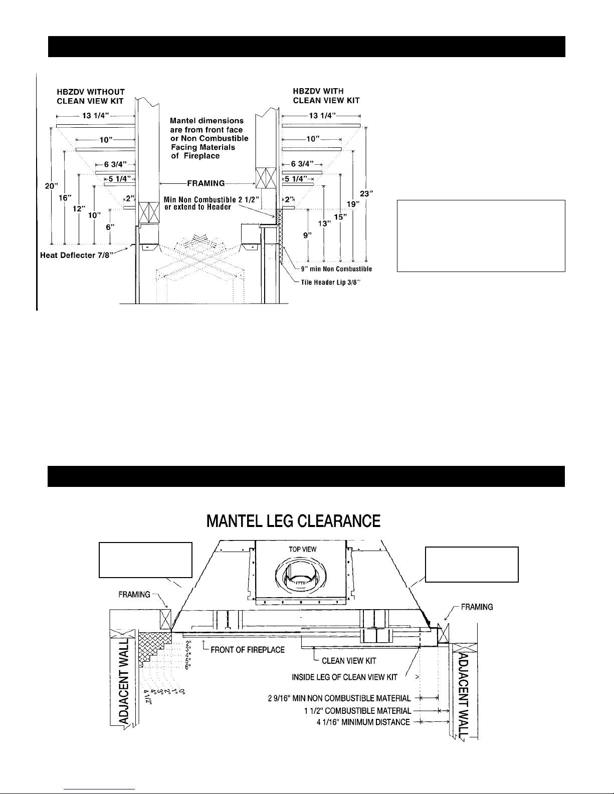
Mantels
Depending on the depth of the fireplace mantel, it may be installed higher or lower from the top of the fireplace opening. See drawings for proper
installation height of your combustible mantel. Non-combustible mantels may be installed at any height above the fireplace opening.
Non combustible materials such as brick, tile, etc. can extend up to or over the front face of the fireplace (NO PORTION OF GRILLAREA OR
DOOR AREAS CAN BE COVERED) except where designer clean view kit is used.
Combustible material can extend flush to unit up to the top, bottom and sides of fireplace to stand-offs.
For COMBUSTIBLE materials extending in front of fireplace consult (Mantel and Mantel Leg Drawings).
Surrounds
If installing wide or slim line surrounds, the finish materials must be flush with the front facing of the fireplace. See page 6, the floor should be built
up 1” in front of the fireplace in order for the surrounds to sit flush to the floor.
Note: When using paint or lacquer to finish the mantel, such paint or lacquer must be heat resistant (250˚F) to prevent discoloration.
Warning: Combustible objects must not be
placed on a non-combustible mantel unless
the non-combustible mantel meets the
minimum height and width requirements for
a combustible mantel.
Mantel Leg Clearances
Mantels & Surrounds
HBZDV with
Louvers
HBZDV with
Clean View Kit
Page 10
10
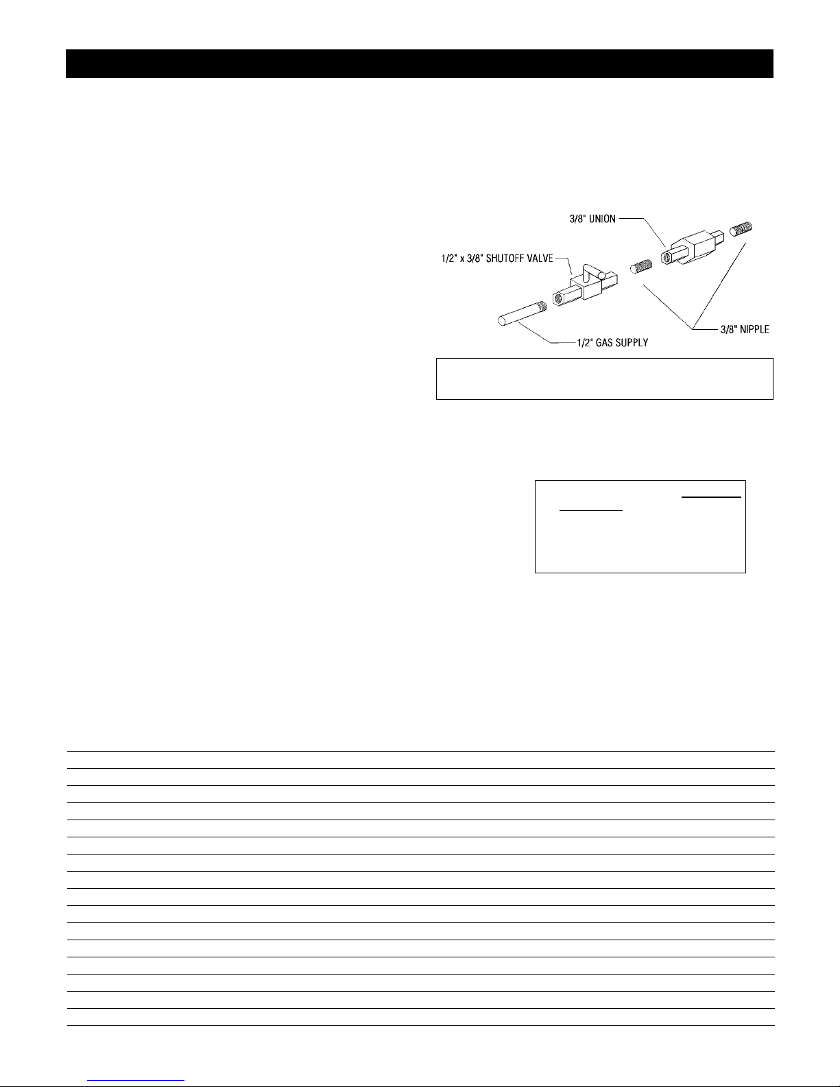
Gas Line Installation
This gas appliance should be installed by a qualified installer in accordance with local
building codes and with current CAN/CGA - B149.1 or .2 installation codes for Gas
Burning appliances and equipment in Canada and the National Fuel Gas Code ANSI
Z223 in the U.S.A.
1. The gas pipeline can be brought in through either the right or the left side of the appliance. Aknockout is provided at either location to allow for the gas pipe installation and
testing of any gas connection.
2. The gas control inlet is 3/8” NPT. Typical installation layout for rigid pipe is shown at
right.
3. When using copper or flex connector, use only approved fittings. Always provide a
union so that gas line can be easily disconnected for burner or fan servicing. See gas
specification for pressure details and ratings.
4. When a vertical section of gas pipe is required for the installation, a condensation trap is
needed. See CAN/CGA-B149.1 or .2 for code details.
5. For natural gas, a minimum of 3/8” iron pipe with gas minimum pressure of 4.5” w.c.
must be used for supply from the gas meter. Consult with the local gas utility if any questions arise concerning pipe sizes.
6. A 1/8” NPT plugged tappings are accessible for test gauge connection both on the inlet
and outlet of the gas valve.
7. Turn the gas supply ON and check for leaks. DO NOT USE OPEN FLAME FOR THIS
PURPOSE. Use an approved leak testing solution.
8. The appliance and its individual shutoff valve must be disconnected from the gas supply
piping system during any pressure testing of that system at test pressures in excess of 1/2
PSIG (3.5 KPa).
9. The appliance must be isolated from the gas supply piping system by closing its individual shutoff valve during any pressure testing of the gas supply piping system at test pressures equal to or less than 1/2 PSIG (3.5 KPa).
Note: The gas line connection may be made of 1/2” rigid pipe or an
approved flex connector. Since some municipalities have additional local
codes, it is always best to consult your local authorities and the current
CAN/CGA - B149.1 or .2 installation code in Canada or the National Fuel
Gas code ANSI Z223.1 in the U.S.A.
Gas Specifications
Top Flue Top Flue
Models HBZDV4224N HBZDV4224LP HBZDV4228N HBZDV4228LP HBZDV4232N HBZDV4232LP
Fuel Natural Propane Natural Propane Natural Propane
Gas Control Millivolt adjustable Millivolt adjustable Millivolt adjustable Millivolt adjustable Millivolt adjustable Millivolt adjustable
Maximum 24,000 BTU High 22,000 BTU High 28,000 BTU High 26,000 BTU High 30,500 BTU High 29,200 BTU High
Input 14,000 BTU Low 15,000 BTU Low 20,000 BTU Low 19,000 BTU Low 20,600 BTU Low 22,200 BTU Low
Maximum n/a n/a 21,000 BTU 19,500 BTU 22,900 BTU 21,900 BTU
Output
Orifice Size #42 #53 #37 #52 #36 #51
(0 - 4500 ft)
Air Shutter .125” – 1/8” Fully Open .218” – 7/32” Fully Open .187” – 3/16” .312” – 5/16”
Gas Inlet Size S.I.T. 820 Nova, 3/8” NPT
Gas Supply Pressure Minimum Normal Maximum
Natural Gas 5.5” 7” 9”
Liquid Propane 11” 11” 12”
Manifold Pressure Natural Gas Liquid Propane
Manifold Pressure High 3.5 IN. W.C./.87 KPa 10 IN. W.C./2.61 KPa
Manifold Pressure Low 1.6 IN. W.C./.40 KPa 6.3 IN. W.C./1.57 KPa
Important: Always check for gas leaks with a soap and water
solution. Do not use open flame for leak testing.
For the state of Massachusetts a T-handle gas
shut-of
f valve
must be used on a gas
appliance. This T-handle gas shut-off valve
must be listed and approved by the state of
Massachusetts. This is in reference to the state
of Massachusetts state code CMR238.
Page 11

11
Fan Installation for HBZDV 36/42/47
Fan Installation instructions for HBZDV36/42/47
with or without CVCK (Clean View Circulating Kit)
1. Slide fan housing into unit and place over 2 Fan Retainer tabs. Tabs are
pre punched and bent up. Rubber grommets at the base of the fan should
fit snugly over the tabs. *Note: When installing fan, lay the fan on its
back and slide into the Fireplace lengthwise. Once inside the fan can be
stood upright and slid behind the valve for placement.
2. Note: For Fan Disc installation HBZDV units have been installed with a
sliding track system. Install the Thermodisc provided with the Fan Kit.
Place thermodisc into sliding assembly, Fig 1, and attach 2 leads exiting
right side of fan housing into thermodisc. Now slide disc assembly into
thermodisc track, Fig 2. Place swivel handle of disc assembly on track to
lock into position. To service disc simply pull swivel handle slide towards
you while rotating handle to access disc.
3. Wire Junction Box to 120v and wall mounted variable speed control.
Install a duplex outlet to junction box and plug fan into outlet.
4. Turn the wall switch on (clockwise). Turn fireplace on. Once the sensor
in unit reaches operating temperature (approximately 10 to 15 minutes)
the fan will turn on. The fan can be switched off if desired by turning the
wall switch fully counter clockwise.
5. To set the minimum fan speed. Remove the variable switch from the wall
mount. Turn the variable speed wall controller to its minimum setting
(fully counterwise). Use the set screw on the side of variable speed controller to increase or decrease the minimum fan speed (lowering minimum fan speed will decrease sound level created by fan)
Reinstall switch into wall mount and cover with face plate.
Parts List:
1 ea. fan comes with 4 ft cord. Two 14’ leads (female ends)
1 ea variable speed control (wall mount type)
1 ea thermodisc
1 thermodisc mount assembly
Electrical Services
All optional fan kits are equipped with a 120V, 60Hz, .4amp blower.
Note: All electric connections are to be made in accordance with CSA
Standard C22.1 - Canadian Electrical Code part I or with the National
Electrical Code, ANSI/NFPA 70 (latest edition) and/or in accordance
with local codes.
WARNING: Electrical Grounding Instructions. This appliance
is equipped with a three-pronged (grounding) plug for your
protection against shock hazard and should be plugged directly
into a properly grounded three-prong receptacle. Do not cut or
remove the grounding prong from this plug.
Caution: Label all wires prior to disconnection when servicing
controls. Wiring errors can cause improper and dangerous
operation.
Verify proper operation after servicing.
Note: INSTALL FAN KIT BEFORE INSTALLING OPTIONAL
CVCK (Clean View Circulating Kit).
If CVCK has been installed into Framing additional access is provid-
ed by removing screws from bottom panel of CVCK. See
INSTALLING CLEAN VIEW KIT (CVCK). Page 8 Ref: C
CAUTION – DO NOT ATTACH 120V FAN ASSEMBLY TO MILLIVOLT GAS VALVE SYSTEM
Note: To service fan with CVCK kit installed see Removing Burner System
in manual.
Page 12

12
Removing Burner System / Access Cover
If Fireplace has been installed with optional CVCK (Clean View
Circulating Kit) to service fan system or burner system controls, the
access cover and burner system will have to be removed
Access cover removal
1. Remove door, logs, brick panels, false bottom, burner grate and
burner from firebox.
2. Lift false bottom up (on applicable units only) from alignment pins
and remove. Burner grate (on applicable units only) is fastened by 2
screws one right and left of grate, remove screws and take out grate.
Remove burner by loosening burner retainer tab screws and slide
burner left off orifice. Access cover is now exposed for removal.
3. Remove 10 screws holding access cover in place. Push down on
one corner of access cover to break seal of cover, once loose cover
can be slid under firebox bottom to expose gas connection.
Removing Burner System
1. Disconnect gas line connection at burner system through access
cover opening.
2. Remove extension knobs and wiring from face of gas valve.
3. Undo screws holding back log holder (on applicable units only) and
remove. Remove screws from perimeter of burner system pan, lift
pan at one back corner and rotate pan up from back of firebox.
Make sure when tilting up and removing burner system, that all fan
and valve control wiring is disconnected. To re-install access cover /
burner system remove old Mil Pac sealant and apply new sealant.
After new sealant is applied reverse removal procedure to re-install
parts.
* Caution high temperature sealant has been applied to access cover
and burner system pan. New sealant will have to be applied when
re-installing access cover and burner stem to maintain the integrity
of sealed combustion chamber. Mil Pac part #840099 or Kingsman
part # 1000-150MP sealant can be purchased from your Kingsman
retailer or distributor.
*Caution before, starting removal of parts turn off gas supply.
Disconnect 110 volts to fan system and disconnect 110 volts to
electronic ignition burner system if applicable.
*Caution all work should be performed by a qualified and
certified technician.
Page 13

13
Millivolt System, Lighting, & Burner Control
Pilot Burner
Adjustment
1. Remove pilot adjustment cap.
2. Adjust pilot screw to provide
proper sized flame.
3. Replace pilot adjustment cap.
4. Leak Test.
Caution: Do Not Wire 120 Volt Power T o Millivolt Switches Or Thermostats.
THERMOCOUPLE
OR GENERATOR
Recommended Maximum Lead Length (Double
Wire) When Using Wall Switch or Thermostat
Wire Size Max. Length
14 GA. 100 FT.
16 GA. 64 FT.
18 GA. 40 FT.
20 GA. 25 FT.
22 GA. 16 FT.
Page 14

14
1. PLACE REAR BRICK PANELAGAINST
REAR OF FIREPLACE.
2. LOOSEN SCREWS HOLDING BRICK
CLIPS IN POSITION. ROTATE CLIPS
UP OUT OF THE WAY. PLACE BOTTOM OF SIDE BRICK OVER FRONT
LIP OF FIREPLACE AND ROTATE
PANEL INTO POSITION. ROTATE
BRICK CLIPS DOWN AND TIGHTEN
SCREWS.
1. REMOVE GLASS DOOR FROM THE
UNIT BY UNLATCHING THE 2 LATCHES ON TOP OF THE UNIT.
2. PLACE REAR BRICK PANEL UP
AGAINST THE REAR OF THE FIREBOX.
3. LOOSEN SCREWS HOLDING BRICK
CLIPS IN POSITION, MOVE CLIPS UP
OUT OF THE WAY AND PLACE SIDE
BRICKS UP TO REAR BRICK AND
FLUSH AGAINST SIDE WALL OF
FIREBOX. POSITION CLIPS OVER
BRICK AND TIGHTEN SCREWS.
4. REPLACE FALSE BOTTOM
5. INSTALL LOGSET AS PER INSTRUC-
TIONS.
6. REATTACH DOOR.
Brick Installation
INSTALLING BRICK PANELS FOR
MODEL HBZDV4224 AND HBZDV4228
INSTALLING BRICK PANELS FOR MODEL HBZDV4232
Page 15

15
Appliance/Log Reference Chart/Log Placement
The following is a list of models and appropriate log sets that can be used with each model. It is important that the appropriate log set is used
with the correct model in order for the appliance to work properly.
Appliance LOGC42 LOGC43 LOGC44 LOGC60
HBZDV4224N or LP
✔✔✔
HBZDV4228N or LP
✔✔✔
HBZDV4232N or LP
✔
Door and Glass Information
Glass Cleaning
It will be necessary to clean the glass periodically. During start-up,
condensation, which is normal, forms on the inside of the glass and
causes dust, lint etc. to cling to the glass surface. Also, initial paint
curing can deposit a slight film on the glass. It is therefore recommended that initially the glass be cleaned two or three times with
non-abrasive
common household glass cleansers and warm water. After
that, the glass should be cleaned two or three times a season depending
on the circumstances.
Cautions and Warnings
• Do not clean when the glass is hot.
• The use of substitute glass will void all product warranties.
• Care must be taken to avoid breakage of the glass.
• Do not operate this fireplace without the glass front or with a broken
glass front.
• Do not strike or abuse glass.
Glass Replacement
REPLACEMENT GLASS FOR BOTH DIRECT
VENT UNITS
Model Series HBZDV4224N and
HBZDV4224LP can use either tempered glass or
Robax ceramic or coated Neaoceram glass.
Must be 5mm thick.
Only Robax ceramic or coated Neaoceram glass
may be used for replacement for model
HBZDV4228N,HBZDV4228LP, HBZDV4232N
and HBZDV4232LP. Must be minimum 5mm
thick.
To replace glass, clean all materials from door
frame. Scrape off old silicone down to metal.
Using a high heat silicone temperature-resistant
to 500°F (260°C) apply a continuous bead of
approximately 1/32” to all four sides of frame
and insert glass with new gasket. Frame should
be on flat surface, with a small amount of weight
pressing glass into silicone. Let dry approximately 15 to 20 minutes. The door can be re-installed
by reversing Steps 1 & 2. Use caution when
removing broken glass, wear gloves.
Removal of the Glass Door
1. Remove the door by unlatching the 2 top latches. Simply place 2
fingers in the grooves, pull towards you and lift upwards slightly.
2. Once the top of the door is unlatched, simply pull outwards and lift
upwards to unlatch the bottom.
3. When re-installing the door place the bottom of the door in first and
secure with Top Latch assembly to the door.
Spring Replacement:
*Over time, spring may need to be replaced if tension is lost.
1. To remove the top latch, remove the 2 hex screws that secure it in
place. They are located in the firebox.
2. Once all the screws are removed the latches will slide out of place.
3. There is 1 lock nut per latch. When replacing a spring, tighten the
lock nut until 2 threads are beyond the locknut. This is critical for
proper tension.
Page 16

16
FIGURE A - Log set Ember kit and Crushed rock
FIGURE B - Rear log holder.
Step (1) Units are equipped with screws or latches. To remove glass
door, either remove screws or unfasten latches and lift door off bottom
door retainer.
Step (2) Remove logs from carton and inspect each log.
Step (3) Verify to see that the ember plates (2 pcs) are between front
and back burner.
Step (4) Break glowing embers into thumbnail size. Place glowing
embers on to the surface of the front burner, to the surface of the ember
plates and over crossover to the same height as ember plates. Height on
front burner 1/2” to 3/4”. Height on ember plates 3/4” to 1”. Do not
cover back air openings on ember plates.
Step (5
) Place front log over burner, against decorative grate. Be
sure that front log is tight up against the decorative grate.
Ember
plate
Air
Opening
Log Assembly for HBZDV4224/HBZDV4228
LOGC42 - LOG C43 LOG PLACEMENT GUIDELINES
(4-PIECE LOG SET)
Page 17

17
Step (6) Place rear log on to the log retainer 1/2” away from back of fire-
place. (If refractory liner is used, make sure refractory liner is installed
first then back log is to be pushed up against it as tight as possible.)
Step (7) Place right crossover log across front and back logs using
the log placement pin as a guide.
Step (8) Place left crossover log across front and back logs using the
log placement pin as a guide.
Step (9) Place decorative moon rock on bottom of fireplace to simu-
late ash.
DO NOT PUT ANY ROCK ON BURNERS!
Step (10) Purge lines and test pilot operation.
Step (11) Replace glass door.
LOG C42 - LOGC43 LOG PLACEMENT (continued) - FOR MODELS HBZDV4224HBZDV4228
Page 18

18
LOGC44 PLACEMENT GUIDELINES - FOR MODELS HBZDV4224/HBZDV4228
FIGURE A - Log set Ember kit and Crushed rock
FIGURE B - Rear log holder. If using LOGC44, bend rear
tabs 90° down.
Step (1) Position rear log over rear log holder and lower into position.
Be sure that the log does not sit on rear burner, but behind and lower
than burner.
Step
(2) Locate flat surface on Log (2) and place directly onto left
ember plate, push log fully to the right until it touches the crossing-
tube.
1
1
4
5
6
3
27
8
2
Tabs
Page 19

19
Step (3) Locate flat surface on Log (3) and place directly on to right
Ember plate, push log fully to the left until it touches Log (2)
Step (4) Remove Ember material from plastic bag, tear off dime and
nickel sized pieces and place directly onto front burner tube and
crossover tube. (NOTE: Do not place embers onto rear burner tube)
Step (5) Position Log (4) into grooved areas of Logs (1) and (2).
Step (6) Position Log (5) into grooved area of Logs (1) and (3).
3
4
5
LOGC44 PLACEMENT GUIDELINES - FOR MODELS HBZDV4224/HBZDV4228
Page 20

20
Step (7) Position Log (6) up against the the 2nd grate post from the
right, and position upper section of Log (6) into grooved area of Log (5).
Step (8) Slide Log (7) between Log (1) and Log (2)
Step (9) Position Log (8) up against the 3rd grate post from the right,
and position upper section of Log (8) against Logs (2) and (7).
Step (10) Place crushed rocks onto firebox bottom.
(NOTE: Do not place crushed rock onto burner tubes)
6
7
8
LOGC44 PLACEMENT GUIDELINES - FOR MODELS HBZDV4224/HBZDV4228
Page 21

2121
Instructions for installing Log Set C-60
for Models HBZDV3632, HBZDV4232, and HBZDV4732
STEP 1: Log 1 is to be positioned onto Pin 1 with locating hole on bottom
of log. The rear right of Log 1 will be placed against stop. (Do not place
log on top of stop.)
STEP 2: Locate the two holes on bottom of Log 2 and position these down
onto the locating Pins 2 and 3.
STEP 3: Place log 3 behind the rear burner tube as shown in the
photograph.
STEP 4: (Note hole on Log 4, bottom of main knot and flat area near end of log.)
Raise Log 3 approx. 2 inches and position Log 4 under the top knot of Log 3. Position
the hole of Log 4 onto locating lobe of Log 1, lower Log 3 down into place as shown.
Place flat area of Log 4 onto left rear burner log mount and push back against tab.
STEP 5: Place Log 5 against grate bars and position Log 6 along side of
Log 5 and onto Log 1 as shown in the photograph.
STEP 6: Place the narrow end of Log 7 onto Log 4. The left front of Log
7 should touch the firebox wall or brick panel.
STEP 7: Place Log 8 onto Log 3. The right front of Log 8 should touch
the firebox wall or brick panel. Verify that Logs 7 and 8 do not extend into
the glass front or enter into the flame path.
STEP 8: Place a small amount of glowing ember material onto the
front burner tube ends. (Too much ember material causes a blue flame.)
(When placing embers onto burner, leave an air space between the log
and the embers; this will help produce a yellow flame in these areas.)
Place rocks onto false bottom only. Do not place rocks onto burner tubes.
LOG 1 LOG 5
LOG 2 LOG 6
LOG 3 LOG 7
LOG 4 LOG 8
❶
❷
❸
❶
❷
❸
❶
❷
❹
❸
❶
❷
❹
❺
❻
❸
❶
❷
❹
❺
❻
❽
❼
❸
❶
❷
❹
❺
❻
❽
❼
PIN 2
PIN 3
PIN 1
STOP
R
R R
R
E
E
E
R
LOBE
Page 22

22
Vent Termination
NOTE: Clearances are to the edge of terminal plate, add 6-3/4” to
clearances to arrive at center line.
NOTE: Local Codes or Regulations may require different
clearances.
Termination
It is imperative that the vent termination be located observing the
minimum clearances as shown. There must not be any obstruction such
as bushes, garden sheds, fences, decks or utility buildings within 24”
from the front of the termination plate.
Do not locate termination where excessive snow or ice build-up may
occur. Be sure to check vent termination area after snow falls and clear
to prevent accidental blockage of venting system. When using snow
blowers, make sure snow is not directed towards vent termination area.
General Venting Information
The gas fireplace is approved to be vented either through the side wall
or vertically through the roof.
This appliance is approved with Kingsman flex vent system and also
approved for use with Simpson Duravent Direct Vent System (model
DV-GS series), AmeriVent Direct Vent Pipe System and Selkirk Direct
Temp.
Kingsman flex vent system can be used with Simpson Duravent Direct
Vent termination’s (model DV-GS series).
When using Simpson Duravent, AmeriVent Direct Vent pipe, or Selkirk
Direct Temp a Kingsman/Duravent adapter must be used.
ONLY VENTING COMPONENTS SPECIFICALLY APPROVED
AND LABELED FOR THIS FIREPLACE MAY BE USED.
Venting terminal shall not be recessed into a wall or siding. If finishing
the outside wall with vinyl or wood siding it is recommended that a
Siding Shield be installed, Part Number ZDVSSLR.
1 - In accordance with the current CSA B149.1, Natural Gas and Propane Code.
2 - In accordance with the current ANSI Z223.1/NFPA 54, National Fuel Gas Code.
3 - Avent shall not terminate directly above a sidewalk or paved driveway that is locat-
ed between two single family dwellings and serves both dwellings.
4 - Permitted only if veranda, porch, deck, or balcony is fully open on a minimum of
two sides beneath the floor.
5 - Clearance in accordance with local installation codes and the requirements of the
gas supplier.
Minimum clearance to combustibles on venting is 1” with the
following exceptions: Top of horizontal 1
1
/2”. Top of 90 degree
elbow in enclosures under 45” to 46” is 5”.Top of 90 degree
elbow in an enclosure over 46” is 2
1
/2”. See pages 7 & 8.
Vent Terminal
Air Supply
Area Where Terminal Not Permitted.
A - Clearance above grade, veranda, porch, deck, or balcony 12 inches
(30cm) minimum.
1-2
B - Clearance to window or door that may be opened. 12 inches (30cm) minimum
for appliances 100 000 Btuh (30 kW) and lower, in Canada. 9 inches
2
(23cm) for appliances 50 000 Btuh and lower, in USA.
C - Clearance to permanently closed window minimum 12 inches (30cm)
recommended to prevent condensation on window, in Canada. 9
inches
2
(23cm) for appliances 50 000 Btuh and lower, in USA.
D - Vertical clearance to ventilated soffit located above the termination
within a horizontal distance of 2 feet (60cm) from the center line of the
termination. 18 inches (46cm) minimum.
5
E - Clearance to unventilated soffit 12 inches (30cm) minimum.
F - Clearance under veranda, porch, deck or balcony 12 inches
1
(30cm)
minimum.
4US5
G - Clearance from a perpendicular inside wall or outer corner to the
edge of the vent terminal plate is 3” (minimum).
H - Clearance to each side of center line extended above meter/regula-
tor assembly 3 feet (91cm) within a height 15 feet (4.5m) above the
meter/regulator assembly.
I - Clearance to service regulator vent outlet 3 feet (91cm) minimum.
1 US5
J - Clearance to non-mechanical air supply inlet to building or the com-
bustion air inlet to any other appliance: In Canada, 6 inches (15cm)
for appliances ≤10,000 Btuh (3kW), 12 inches
1
(30cm) minimum for
appliances >10,000 Btuh(3kW) and ≤100,000 Btuh (30kW), 36 inch-
es (91cm) for appliances >100,000 Btuh (30kW). In the USA, 6 inches
2
(15cm) for appliances ≤10,000 Btuh (3kW), 9 inches (23cm) for
appliances >10,000 Btuh (3kW) and ≤50,000 Btuh (15kW), 12 inch-
es (30cm) for appliances >50,000 Btuh (15kW).
K - Clearance to a mechanical air supply inlet 6 feet (1.8m) mini-
mum.
1
,in Canada. In USA, 3 feet (91cm) above if within 10 feet
2
(3m) horizontally.
L - Clearance above paved sidewalk or a paved driveway located on
public property 7 feet (2.1m) minimum.
3
M - Clearance above highest point of exit on roof 18 inches (45cm).
N - Clearance to perpendicular wall 24 inches (60 cm).
(Recommended to prevent re-circulation of exhaust products. For additional
requirements check local codes.)
V
Page 23

23
Venting Routes And Components
Since it is very important that the vent system maintain its balance
between the combustion air intake and the flue gas exhaust, certain limitations as to vent configurations apply and must be strictly adhered to.
The table showing the relationship between vertical and horizontal side
wall venting will help to determine the various vent lengths.
The maximum horizontal run with the 90 degree bend at the fireplace
flue outlet is 4 ft/122cm (Figure #1). The maximum horizontal run is
20 ft/6.1 m when the vertical run is 7 ft/2.1m (Figure #2). Note: 1/4”
vertical rise is required for every 12” of horizontal run.
The maximum number of 45 degree bends per side wall installation is
two (2) in the horizontal run and then you must reduce the length of the
horizontal by 18 inches for each 45 degree bend.
The maximum vertical run is 40 ft/12.2 meters.
Special Note: For each 45 degree bend installed in the horizontal
run, the length of the horizontal run must be reduced by 18”
(45cm). This does not apply if the 45 degree bends are installed on
the vertical part of the vent system.
Example: If according to the table, the length of the horizontal run is
10 feet, and two 45 degree bends are required, the horizontal run length
must be reduced to 7 feet.
2 additional 90° bends or equals are allowed. The horizontal run must
be reduced by 36” per each 90° bend, or 18” per each 45° bend.
How To Use The Horizontal Vent Table
1. Determine the height of the system and the number of bends
required.
2. Having determined the vertical distance determine the maximum
horizontal section allowed.
3. Vent table has been established for 90˚ horizontal/vertical runs.
With use of flex pipe distance not having 90˚ bends will not fall into
vent table standards. See Fig. B.
Horizontal Venting Table From Bottom of Fireplace
for venting to a maximum of 40 ft. (12.2 meters)
Total Vertical Max Total Horizontal
Feet Meters Feet Meters
4 1.2 5 1.5
5 1.5 8 1.2
6 1.8 12 3.7
7 2.1 20 6.1
8 2.4 20 6.1
9 2.7 20 6.1
10 3.0 20 6.1
11 3.4 20 6.1
12 3.7 20 6.1
13 4.0 20 6.1
14 4.3 20 6.1
15 4.6 20 6.1
16 4.9 20 6.1
17 5.2 20 6.1
18 5.5 20 6.1
19 5.8 20 6.1
20 6.1 20 6.1
25 7.5 15 4.6
30 9 10 3.0
40 12.2 0 0
Example A:
If the vertical dimension from
the floor of the fireplace is 6ft,
the horizontal run to the wall
flange of the vent termination
must not exceed 12ft.
NOTE:The final location of
the fireplace must be such
that the horizontal vent
dimensions fall within those
stated on the graph. The
Maximum Vertical vent run
is 40ft. (12.2 meters).
Important: Always locate the fireplace in such a way that a minimum of off-
sets and/or horizontal runs are required. 1/4” vertical rise is required for every
12” horizontal run.
Important: Minimum clearance between vent pipes and
combustible materials is 1 inch
(25mm).
12 ft.
6 ft.
37"
MINIMUM
SUPPORT STRAP ON
90° BEND
MAX. HORIZONTAL
FIGURE A
FIGURE B
TOTAL VERTICAL
It is recommended for Propane Horizontal Installations that the
venting should be a minimum of one foot vertical off the flue
before the elbow on any horizontal runs of one foot or greater.
This allows for cleaner combustion and greatly reduces carboning
and cleaning of glass. (Does not apply to Back Flue Models).
20 FEET
Page 24

24
General Vent Installation Information
This gas appliance is approved to be vented either through the side wall or vertically
through the roof. Only Kingsman venting kits and components specifically
approved and LABELED for this stove may be used. This appliance is also approved
for use with Simpson-Duravent Direct Vent system, Model DV-GS Series, Ameri-Vent
Direct Vent Pipe System, and Selkirk Direct Temp.
SIMPSON DURAVENT, AMERIVENT OR SELKIRK DIRECT TEMP
When using Simpson Duravent, AmeriVent pipe, or Selkirk Direct Temp a Duravent
adapter must be used (part # ZDVDF Afor fireplaces). Follow installation instructions
provided by Simpson Duravent for installation of pipe and adhere to the clearance to
combustibles provided in this manual. Apply a bead of Mill Pac high temp sealant to all
joints of pipes, adapters and termination as recommended.
Flex Pipe Venting
Flex pipe is shipped in unexpanded length. When installing pipe expand the lengths.
Pipe can be expanded to twice their lengths e.g. 4ft. to 8ft. Fully extend pipe and cut off
remaining pipe.
Do not use more than 2 couplers to extend short pipes. Single sections are preferred in
an installation attaching at the fireplace and termination.
Place the spring spaces provided approximately every two feet to stabilize 4” flex in the
center of 7” flex. When forming bends place spring in bend or before and after. (See Fig. 1).
Horizontal runs require support metal straps every 2 feet. In off set installation support
straps should be used to stabilize pipe.
Expand 4” and 7” flex pipe to the point that the 7” protrudes approximately 2 to 3 inches past outer wall and the 4” flex protrudes approximately 2 to 3 inches past the 7” flex.
See Fig. 1. Attach the 4” pipe to the termination first and secure with sealant and screws
then attach the 7” flex to the termination with caulking and screws. Termination may
then be moved back to the outer wall and attached to home screwing into the framing.
Silicone around termination to waterproof. If siding shield is going to be used attach this
using same attaching hole as the top of termination after termination has been caulked
for water proofing.
Use Hi Temp Sealant
Apply a bead of mill pac high temp sealant to all joints and use four screws to secure
each pipe at fireplace, termination and any joint if joining any sections of pipe.
Installation Of Side Wall Venting
1. The minimum distance from the bottom of fireplace to centre of vent is 36 inch
(85 cm) (See Figure 1). Cut a hole through the wall allowing for a 11” x 11”
(inside diameter) in combustible walls for wall thimble or an 8” diameter hole in a
non-combustible wall (See Figure 2).
2. Note clearance to combustibles are as stated on pages 7 & 8.
3. Select the approximate vent length, precise measurements are not needed as your
flex pipe can be expanded to twice its shipped length for ease of installation.
4. To install wall thimble centre over 11” x 11” (inch) framing from both sides of
wall and secure. Route flex vent pipe through wall thimble (See Figure 1).
5. Before joining pipes, apply a bead of high temperature sealant (Mill Pac) to end of
pipe. First attach the four inch (4”) flue pipe to the vent termination with sealant,
and secure with the four screws provided. At this time make sure the spacer
springs are attached to the (4”) flex pipe as required. Then attach the seven inch
(7”) pipe by the same method.
6. Mount vent termination and seal to wall using caulking around the wall thimble to
weather proof. After installing the vent termination, double check to make sure the
pipe extends properly through wall thimble and into vent termination.
7. Before joining pipes to fireplace flue, apply a bead of high temperature sealant
(Mill Pac) to end of pipe. First attach the four inch (4”) flue pipe to fireplace with
sealant, and secure with the four screws provided. At this time verify that the
spacer springs are attached properly to the (4”) flex pipe as required. Then attach
the seven inch (7”) pipe by the same method.
8. Support horizontal pipes every two (2) feet (61 cm) with metal strap bands. Recheck fireplace to make sure it is levelled and properly positioned and secured.
9. Support vertical pipes to maintain a minimum of 1” or greater clearance to combustibles with metal strapping bands.
10. If finishing the outside wall with vinyl or wood siding it is recommended that a
Siding Shield be installed, Part Number ZDVSSLR.
Note: Vent Termination must not be recessed into wall or siding.
NOTE:It is critical to the proper and safe operation of
this fireplace that on all connections the inner liner and the
outer casing are both caulked with liberal amounts of
sealant. Do not use any kind of tape or silicone other than
that recommended in this manual. Mill Pac Sealant
FRAMING DIMENSION
Combustible Wall
Cut a 11” hole through exterior wall and frame as shown
below.
Non combustible Wall
Cut or drill 8” or 204mm diameter hole.
FIGURE 1
FIGURE 2
MINIMUM OF
1.0" TO
COMBUSTIBLES
36.0"
MINIMUM
COMBUSTIBLE AIR INLET
FLUE GAS OUTLET
37.125"
17.0"
FRAMING DETAIL
11.0"
11.0"
8" DIA
36.0" TO CENTERS
MINIMUM
THROUGH COMBUSTIBLE
WALL
THROUGH NON-COMBUSTIBLE
WALL
Note: W all Thimbles cover com-
bustible wall up to 11” thick.
OPTIONAL
CLAMPS
FIGURE 1
MAX. DISTANCE BETWEEN SPACERS 2 FEET
SPRING SPACERS
OPTIONAL
CLAMPS
SEAL WITH HIGH TEMP. SEALANT
SEAL WITH HIGH TEMP. SEALANT
Page 25

25
Using Flex Bends
4. Avoid cutting joists by offsetting the flex pipe. See Fig. 2.
5. When using 45˚ bends a bend support is required directly above the highest
bend.
6. When installing a bend in a joist area a minimum of 2
1
/2” clearance to combustible to the top of bend must be maintained, sides and bottom of pipe, a
1” clearance to combustibles must be maintained. If running horizontal
through an area a 1
1
/2” minimum clearance to the top of the horizontal pipe
must be maintained.
7. Maximum vertical height of system should not exceed 40 feet.
8. Use roof support and 7” rigid pipe at roof level. Flex not permitted within
roof support.
9. When penetrating the roof a rigid 7” galvanized pipe must be used. Attach
the 7” flex to the 7” rigid with high temperature sealant, secure with four
screws assuring the flex and rigid pipe are secured. 4” flex pipe must be
secured the same way with 4 screws but must penetrate the 4” flex and 4”
section of termination. Attach 7” rigid pipe to 7” termination with sealant
and screw with 4 sheet metal screws. (See Fig. 3).
10. Vertical termination clearance is 18” (inches) above the roof, measured
from highest point of exit on the roof line.
11. Support vertical pipes to maintain minimum of one inch or greater clearances to combustibles.
FIG. 1
FIG. 2
Venting Straight Up Through Roof
1. An Attic Insulation Shield must be installed where the vent passes from a
lower living space into an attic space where the chimney is not enclosed. It
is designed to keep insulation materials away from the chimney. See Fig. 1.
2. When installing the Attic Insulation Shield where the chimney passes from
a living space to an attic space, install the shield from below and nail in
place using 1” spiral nails.
3. A fire stop must be installed on the bottom side of the joists when passing
through a ceiling or floor. If an attic insulation shield is to be used, a fire
stop is not required.
FIG. 3
Roof Flashing
Ensure that you have the proper roof flashing by checking your roof
pitch using a level and two rulers, or by using a roof pitch card.
See figure below.
Slide a Roof Flashing suitable to your roof slope over the vent. Place
the edge of the flashing plate that will be on the higher part of the roof
slope under the shingles. Both the sides and the lower edge lay on top
of the shingles.
NOTE:At the top edge of the flashing plate, lift the shingles and
nail the plate to the roof deck, then cement the shingles to the plate
with a suitable waterproof mastic.
Ensure that the chimney is plumb. Square up the flashing plate and nail
in place to the roof deck. Use 12 nails with neoprene washers or cover
the heads with a suitable waterproof mastic.
Wrap the storm collar around the vent above the flashing. Secure the
ends together loosely with nut and bolt supplied. Slide the collar down
the vent until it comes in contact with the flashing. Tighten the bolt and
seal the Storm Collar to the vent with a suitable waterproof non-combustible mastic.
The flashing and storm collar should be painted to match the roof
shingles. This will extend its life and improve the appearance. Clean,
prime and paint with suitable painting products.
1.5” Top of Horizontal Vent
2.5” Minimum Top of 90° Elbow
All other existing pipes 1” clearances to combustibles.
Support Straps required to maintain rise in venting.
OPTIONAL
Page 26

26
SECTION A
Step 1: Remove the 2 ember plates from the burner.
This step may not be required, depending on
the type of burner assembly.
Step 2: Loosen the 2 screws holding the burner in
place.
Step 3: Slide the burner to the left to expose the orifice.
Step 5: Remove the 2 screws that hold the pilot to
the bracket.
Step 6: Remove the 2 screws that attach the pilot
bracket to the firebox bottom.
Step 7: Remove the pilot bracket to expose the pilot
assembly.
Step 8: Remove the pilot tube and nut from the pilot
assembly using a 10mm wrench, slide the
tube and nut down. You may have to tap the
pilot hood lightly to release the pilot orifice.
Place new pilot orifice into the pilot assembly and reinstall the pilot tube and nut.
Tighten with wrench.
Reinstall pilot br
acket at this time.
Step 9: Remove main orifice using a 1/2” wrench
and replace with new conversion orifice.
Step 10: Adjust the primary air setting to the correct
setting as specified in the manual or label
plate. To adjust the air setting, loosen the
screw on the side of the tube and rotate to
the correct opening using a drill bit or tape
measure. Retighten screw.
Reinstall burner at this time rev
ersing STEPS
3, 2 and 1.
Step 11: Follow instructions supplied with the conver-
sion HI LOW to convert the valve from one
type of fuel to the other.
Step 12: Check for gas leaks around the pilot burner
tube and face of valve.
Step 13: Attach conversion label to label plate on bot-
tom of unit, writing information as needed.
CONVERSION KIT INSTRUCTIONS
Step 4: Before going any further you need to verify
which pilot system is in use:
– If there is a spring clip below the pilot
hood, proceed to the other side of page,
Section B, Step 5.
PLEASE CONFIRM THAT STEP 4 IS UNDERSTOOD
BEFORE PROCEEDING WITH CONVERSION.
“Warning”
This conversion kit shall be installed by a qualified service agency in accordance with the manufacturer’s
instructions and all applicable codes and requirements
of the authority having jurisdiction. If the information
in these instructions is not followed exactly, a fire,
explosion or production of carbon monoxide may
result causing property damage, personal injury or loss
of life. The qualified service agency is responsible for
the proper installation of this kit. The installation is not
proper and complete until the operation of the converted appliance is checked as specified in the manufacturer’s instructions supplied with the kit”
Page 27

27
SSSSeeeeccccttttiiiioooonnnn BB
BB
IIIInnnnssssttttaaaallllllllaaaattttiiiioooonnnn IIIInnnnssssttttrrrruuuuccccttttiiiioooonnnnss
ss
GAS CONVERSION KIT FOR TOP
CONVERTIBLE PILOT
SERIES 019065X
SIT Group
Instructions for converting SIT 190 series pilot burner injection from NG to LPG and from NG to LPG Only.
This information should be considered as supplemental to the Appliance Manufacturer’s Instructions.
WARNING!
The installation of this conversion kit must only be undertaken by a qualified
and certified gas appliance installer.
1
Shut off the gas supply to the appliance.
2
Allow the pilot burner to cool to room temperature.
WARNING: Touching a hot pilot burner can result in injury.
3
The pilot hood is held in place by spring pressure.
Remove the hood by pulling it directly up from the pilot bracket (1).
4
Insert a 5/32” or 4mm Allen wrench into the hexagonal key-way of the
injector (2), and rotate it counter clockwise until it is free of the injector
journal (3).
5
Verify that the new injector is proper for the application. The injector size
is stamped on the side of the injector near the top. LPG injectors have a
groove machined around their circumference near the top, while NG
injectors do not have a groove (5).
Refer to the Appliance Manufacturers instruction sheet for the proper
injector size.
6
Insert the Allen wrench into the end of the injector. Then, insert into injector journal, and rotate the injector clockwise until a torque of 9 in-lbs. is
achieved.
7
Replace the pilot hood by aligning the tab on the base of the hood with
the slot in the side of the pilot journal, and push the hood down, directly
onto the pilot bracket (4). The hood must sit squarely on the bracket for
proper operation. Check to insure that the hood is properly seated onto
the pilot bracket.
8
Proceed to Section A, Step 9.
WARNING!
This conversion kit must only be applied as part of a conversion kit supplied by the
appliance Manufacturer for the specific appliance, and type of gas being converted.
INSTALLER NOTICE. These instructions must be left with appliance.
Page 28

28
Fireplace Part Numbers
HBZDV4224N FIREPLACE DECORATIVE RATED NG,
TEMPERED GLASS, 24,000 BTU WITH GLOWING
EMBER BED, BEDROOM APPROVED
HBZDV4224LP FIREPLACE DECORATIVE RATED LP, TEMPERED
GLASS, 22,000 BTU WITH GLOWING EMBER
BED, BEDROOM APPROVED
HBZDV4228N FIREPLACE HEATER RATED NG, CERAMIC
GLASS, 28,000 BTU WITH GLOWING EMBER BED
BRA-MHA
HBZDV4228LP FIREPLACE HEATER RATED LP, CERAMIC
GLASS, 26,000 BTU WITH GLOWING EMBER BED
BRA-MHA
HBZDV4232N FIREPLACE HEATER RATED NG, CERAMIC
GLASS, 30,500 BTU AT 75% EFFICIENT.
APPROVED FOR BEDROOM AND MOBILE
HOME.
HBZDV4232LP FIREPLACE HEATER RATED LP, CERAMIC
GLASS, 29,200 BTU AT 75% EFFICIENT.
APPROVED FOR BEDROOM AND MOBILE
HOME.
FIREPLACE REQUIREMENTS
Grills or CVCK (clean view circulating kit)(Required
for each unit)
HB42CVCK CVCK(clean view circulating kit) no grill required
HB42GBA Grill Kit - Classic Builder Antique Brass
HB42GBC Grill Kit - Classic Builder Chrome
HB42GBP Grill Kit - Classic Builder Polish Brass
HB42GBL Grill Kit - Black
HB42PBL Panel Grill Kit - Black
LOG SETS: (Required for each unit)
LOGC42 Log Set - 4 pce. - Classic Oak (ZDV3320,
HB3624/28, HB4224/28 Series)
LOGC43 Log Set - 4 pce. - Traditional Oak (ZDV3320,
HB3624/28, HB4224/28 Series)
LOGC44 Log Set - 8 pce. - Burnt Oak (ZDV3320,
HB3624/28, 4224/28 Series) Not for use in
back flue models.
LOGC60 Log Set - 7 pce. - Burnt Oak (HBZDV3632,
HBZDV4232, HBZDV4732 Series)
Fireplace Surrounds
HB42SAB Surround - Antique Brass
(Coverage New Style 37 5/8” H x 45 1/8” W)
HB42SBL Surround - Black
(Coverage New Style 37 5/8” H x 45 1/8” W)
HB42SCR Surround - Chrome
(Coverage New Style 37 5/8” H x 45 1/8” W)
HB42SPB Surround - Polish Brass
(Coverage New Style 37 5/8” H x 45 1/8” W)
HB42SLAB Surround Slim Line - Antique Brass
(Coverage 37 3/8” H x 43 3/8” W)
HB42SLCR Surround Slim Line - Chrome
(Coverage 37 3/8” H x 43 3/8” W)
HB42SLPB Surround Slim Line - Polish Brass
(Coverage 37 3/8” H x 43 3/8” W)
HB42SLBL Surround Slim Line - Gun Metal Black
(Coverage 37 3/8” H x 43 3/8” W)
Overlays
HB42ADTH Arch Door Frame - Top Half Black
HB42ADDX Arch Door Frame - Deluxe Black
HB42ADDA Arch Door Frame - Double Arch Black
HB42ADDD Arch Door Frame - Double Door Arch Black
Parts List
Accessories
Z36FK Fan Kit w/Variable Speed Wall Mount Control
(Temperature Sensing)
Z1MT Thermostat Millivolt Wall Mount
Z80PT Thermostat Programmable Digital Millivolt
Wall Mount (1F80-40)
Z1RC Remote Control Millivolt (On/Off with LED)
(Model I)
ZART Remote Control Thermostst Millivolt (Model K)
RMCBN Remote Control - Basic - Natural Gas
(On/Off, Hi/Lo Flame Adjustment)
RMCBP Remote Control - Basic - Liquid Propane
(On/Off, Hi/Lo Flame Adjustment)
DCHS Remote Control Heatshield
HB42RLT Refractory Liner Traditional
HB42RLH Refractory Liner Herring Bone
Designer Doors for 42” Fireplaces - Operative
HB42DDA1BL Designer Door Arch - Series 1 - Black
HB42DDTA1A Trim - Antique for Designer Arch - Series 1
HB42DDTA1C Trim - Chrome for Designer Arch - Series 1
HB42DDTA1P Trim - Polish Brass for Designer Arch - Series 1
HB42DDS1BL Designer Door Straight - Series 1 - Black
HB42DDTS1A Trim - Antique for Designer Straight - Series 1
HB42DDTS1C Trim - Chrome for Designer Straight - Series 1
HB42DDTS1P Trim - Polish for Designer Straight - Series 1
Child Safety Screens
HB42CSS Child Safety Screen - 42” HBZDV Fireplaces
HB42PSK Pull Screen Kit for CVCK
Replacement Burner Assembly
4224HB-BNGSI BURNER ASSEMBLY - NATURAL GAS C/W
VALVE SYSTEM (HBZDV4224N)
4224HB-BLPSI BURNER ASSEMBLY - LIQUID PROPANE C/W
VALVE SYSTEM (HBZDV4224LP)
4228HB-BNGSI BURNER ASSEMBLY - NATURAL GAS C/W
VALVE SYSTEM (HBZDV4228N)
4228HB-BLPSI BURNER ASSEMBLY - LIQUID PROPANE
C/W VALVE SYSTEM (HBZDV4228LP)
4232HB-BNGSI BURNER ASSEMBLY - NATURAL GAS C/W
VALVE SYSTEM (HBZDV4232N)
4232HB-BLPSI BURNER ASSEMBLY - LIQUID PROPANE
C/W VALVE SYSTEM (HBZDV4232LP)
Valve System Parts - New Top convertible SIT
1000-P136WR Thermopile GOAI-524
1001-P069SI Electrode Sparker 915.069 TC SIT
1001-P216SI Thermocouple 290.216 TC SIT
1001-P165SI Orifice Pilot NG 977.165 TC SIT
1001-P167SI Orifice Pilot LP977.167 TC SIT
1001-P508SI HTCable 16
1001-P633SI Valve Nova LP Hi/Lo 0820633
1001-P634SI Valve Nova NG Hi/Lo 0820634
1001-P713SI Pilot Burner LP199.713 TC SIT
1001-P714SI Pilot Burner NG 199.714 TC SIT
Page 29

29
Miscellaneous Parts
1000-150GE #SILICONE GE RED IS806 #736
1000-150MP #HI-TEMP MILL PAC SEALANT 840099
1000-214 #PIEZO-IGNITOR 1244-17 MARK 21
1000-215 #PALNUT (18MMXI.5MM)BLK (1364.03)
1000-218 #SWITCH IVORY (1451/001)
1000-227 #COVER IVORY (86001/001)
1000-255 #ORIFICE BRASS - (State Size)
1000-EMBER #MOON ROCK
2000-080 #THERMODISC 2450 (For Blower)
2000-081 #BLOWER MOTOR QLN65/2400
1000-085 #CONTROL VARIABLE SPEED KBWC-13BV
1000-306 THERMALCORD - ADHESIVE BACK FOR
DOOR FRAME
42HB-310 CERAMIC GLASS - FOR ALLHBZDV4200
42HB-311 TEMPERED GLASS - FOR HBZDV4224 MODEL
36HB-123 UPPER DOOR SPRING
Conversion Kit (Sit Valve Only)
4224HB-CKLP LP Conversion Kit for HBZDV4224
4224HB-CKNG NG Conversion Kit for HBZDV4224
4228HB-CKLP LP Conversion Kit for HBZDV4228
4228HB-CKNG NG Conversion Kit for HBZDV4228
4232HB-CKLP LP Conversion Kit for HBZDV4232
4232HB-CKNG NG Conversion Kit for HBZDV4232
Page 30

30
Trouble Shooting The Gas Control System
WARNING: BEFORE DOING ANY GAS CONTROL SERVICE WORK, REMOVE THE GLASS FRONT.
NOTE: Before troubleshooting the gas control system,be sure external gas shut off is in the “On” position.
Problem Possible Causes Corrective Action
Spark igniter will not light. Defective or misaligned electrode Check for spark at electrode and pilot: if no spark and electrode wire is
at pilot. properly connected, replace igniter.
Defective igniter Using a match, light pilot. If pilot lights, turn off pilot and push the red
(push-button) button again. If pilot will not light - check gap at electrode and pilot
should be 1/8” to 1/4” to have a strong spark.
Pilot will not stay lit after carefully Defective thermocouple Check pilot flame. Must impinge on generator and thermocouple.
following lighting instructions. (flame switch where applicable) Clean and/or adjust pilot for maximum flame impingement on
generator and thermocouple. Replace thermocouple if pilot will not
hold. (Hand tight 1/8 turn on replacement)
Defective valve magnet. Replace valve, if pilot won’t hold after the thermocouple is replaced.
Pilot burning, no gas to burner, Wall switch or wires Check wall switch and wires for proper connections. Jumper wire
Valve knob “ON”, Wall defective. across terminals at wall switch. If burner comes on, replace defective
Switch “ON” wall switch. If okay, jumper wires, across wall switch wires at valve.
If burner comes on, wires are faulty or connections are bad.
Generator may not be generating Check generator with millivolt meter. Take reading at generator termisufficient voltage. nals of gas valve. Should read 325 millivolts minimum while holding
valve knob depressed in pilot position and wall switch “off” Replace
faulty generator if reading is below specified minimum.
Plugged burner orifice. Check burner orifice for stoppage and remove.
Defective automatic valve Remove wall switch wires from gas valve. Install jumper wires from
operator. top bottom terminals of gas valve. Turn valve on “ON”. If main burner
does not light, replace valve.
Frequent Pilot outage problem. Pilot flame may be too low or Clean and/or adjust pilot flame for maximum flame impingement
blowing (high) causing the pilot on generator and thermocouple.
safety to drop out.
Flame lifts off burner and goes out Inner 4” liner has come off flue Attach 4” liner to flue or termination using
in less than 30 seconds or termination, flame is starving screws, silicone and clamps as stated in manual
for oxygen
Flame lifts off burner on Improper installation of firebrick. Be sure to postion firebrick against firebox walls and
one side while the rest of Firebrick is likely leaning. be sure to use brick clips attached to the inner side
the flame remains lit. of firebox.
Kingsman Fireplace Venting
Catalog
Number Description
ZDVHSK Horizontal Vent Starter Kit - 3 FT Length
Horizontal Vent Termination, W all Thimble,
36” Flex Pipe, Mill Pac, screws/washers, springs.
ZDVHSK5 Horizontal Vent Starter Kit - 5 FT Length
Horizontal Vent Termination, W all Thimble,
60” Flex Pipe, Mill Pac, screws/washers, springs.
FDVVT40 Vertical Vent Termination converts from
15’-40’to 15’and under
FDVHT Horizontal Vent Termination
FDVHSQ Horizontal Square Termination
ZDVST Horizontal Snorkel Termination
(34” Tall, 24” Center to Center)
FDVHSCU Safety Cage for Horizontal Termination
ZDVAIS Attic Insulation Shield
ZDVVOS Offset Support
ZDVFS Firestop Spacer
ZDVRS Roof Support
ZDVWT Wall Thimble (Horizontal Venting)
ZDVSSLR Siding Shield - Large Return
ZDV48GP Galvanized Pipe 7” Dia. x 48” (Vertical Installations)
ZDVAAF Flashing 7” c/w Storm Collar (1/12 to 7/12)
ZDVAF2 Flashing 7” c/w Storm Collar (8/12 to 12/12)
ZDVAF3 Flashing 7” c/w Storm Collar Flat
ZDV7SC Storm Collar 7”
ZDVFK5 Flex Kit (4” & 7” Dia.) x 2.5’(Unexpanded) 5’Expanded
ZDVFK8 Flex Kit (4” & 7” Dia.) x 4’(Unexpanded) 8’Expanded
ZDVFK20 Flex Kit (4” & 7” Dia.) x 10’(Unexpanded) 20’Expanded
*Kits are complete with spring stand-offs, silicone.
ZDV4FC Flex Connector 4” Diameter
ZDV7FC Flex Connector 7” Diameter
ZDV4SS Spring 4” Standoff Spacer
ZDVDFA Simpson Dura-Vent Fireplace Adapter
(for ZDV33/36/42/47, ZDV6000, MDV30/38 & HB models)
ZDVHSKSQ Horizontal Square Termination Vent Starter Kit -
3 FT Length
Horizontal Vent Termination, W all Thimble,
W all Thimble, 36” Flex Pipe, Mill Pac
FDVHSQ Horizontal Square V ent Termination
Page 31

BASIC ONE YEAR WARRANTY
During the first year after installation, we will provide a replacement for any component part of your unit found to be defective in materials
or workmanship, including labour costs. Repair work requires prior approval by Kingsman, labour costs are based on a predetermined rate
schedule and any repair work must be done through an authorized Kingsman dealer.
LIMITED LIFETIME WARRANTY
The heat exchanger, combustion chamber and burner of every Kingsman product excluding the Outdoor Firepit are warranted against
materials or workmanship during the period the product is owned by the original owner. The part to be replaced must be returned to our
distributor in exchange for the replacement part. Any labor, material, freight and/or handling charges associated with any repair
or replacement pursuant to this Limited Lifetime Warranty will not be covered by this warranty.
GENERAL TERMS
In lieu of providing a replacement part, we may, at our option, provide the distributor's component purchase price from us or a credit equal
to the distributors component purchase price from us toward the purchase of any new unit which we distribute. If a credit is given
in lieu of a replacement part, the rating plate from the unit being replaced must be submitted on a warranty claim, and the unit being
replaced must be made available to our distributor for disposition.
In establishing the date of installation for any purpose, including determination of the starting date for the term of this Limited Lifetime
Warranty, reasonable proof of the original installation date must be presented*, other wise the effective date will be based upon the date of
manufacture plus thirty (30) days.
We will not be responsible for and you, the user, will pay for: (a) damages caused by accident, abuse, negligence, misuse, riot, fire, flood,
or Acts of God (b) damages caused by operating the unit where there is a corrosive atmosphere containing chlorine, fluorine, or any other
damaging chemicals (other than in a normal residential environment) (c) damages caused by any unauthorized alteration or repair
of the unit affecting its stability or performance (d) damages caused by improper matching or application of the unit or the unit's components
(e) damages caused by failing to provide proper maintenance and service to the unit (f) any expenses incurred for erecting, disconnecting
or dismantling the unit (g) parts or supplies used in connection with service or maintenance (h) damage repairs, inoperation or inefficiency
resulting from faulty installation or application (i) electricity or fuel costs or any increase in electricity or fuel cost whatsoever including
additional or unusual use of supplemental electric heat.
We shall not be liable for any incidental, consequential, or special damages or expenses in connection with any use or failure of this unit.
We have not made and do not make any representation or warranty of fitness for a particular use or purpose, and there is no implied condition
of fitness for a particular use or purpose. We make no express warranties except as stated in this Limited Lifetime Warranty. No one is authorized
to change this Limited Lifetime Warranty or to create for us any other obligation or liability in connections with this unit. Any implied
warranties shall last for one year after the original installation. Some states and provinces do not allow the exclusion or limitation of incidental
or consequential damages or do not allow limitations on how long an implied warranty or condition lasts, so the above limitations or exclusions may not apply to you. The provisions of this limited warranty are in additions to and not a modification of or subtraction from any statutory warranties and other rights and remedies provided by law.
Save this certificate. It gives you specific legal rights, and you may also have other rights which may vary from state to state and province to province.
In the event your unit needs servicing, contact your dealer or contractor who installed or serviced your unit. When requesting service,
please have the model and serial number from each unit readily available. If your dealer needs assistance, the distributor is available for support
and we, in turn support the distributor's efforts.
Fill in the installation date and model and serial numbers of the unit in the space provided below and retain this limited warranty for your files.
Model No. Serial No. Date installed
Dealer or Contractor Name:
*
To receive advantage of your warranty, you must retain the original records that can establish the installation date of your unit.
LIMITED LIFETIME WARRANTY
This Limited Lifetime Warranty applies only while the unit remains at the site of the original
installation and only if the unit is installed inside the continental United States, Alaska, Hawaii,
and Canada. The warranty applies only if the unit is installed and operated in accordance
with the printed instructions and in compliance with applicable installation and building codes
and good trade practices.
The Ultimate in Design, Engineering & Quality
 Loading...