

Kingsman GLVF24MAN, GLVF24MAP, GLVF24MVN, GLVF24MVP Owner's Operation And Installation Manual
Page 1
INSTALLER: Leave this manual with the appliance.
CONSUMER: Retain this manual for future reference.
2340 Logan Ave., Winnipeg, MB, Canada, Phone: (204) 632-1962 Printed in Canada June 26, 2015 Part # 24GL-MAN
This appliance must be
installed by a licensed
plumber or gas fitter in
the Commonwealth of
Massachusetts and meet
the requirements of 527
CMR 30 and 248 CMR.
⚠ -WARNING-
FOR USE ONLY WITH
A LISTED GAS-FIRED
UNVENTED
DECORATIVE ROOM
HEATER
NOT TO EXCEED
40,000 BTU/H.
DO NOT BUILD A WOOD
FIRE.
⚠ -WARNING-
Carefully review the instructions
supplied with the decorative
type unvented room heater for
the minimum fireplace size
requirement.
DO NOT INSTALL AN
APPLIANCE IN
THIS FIREBOX UNLESS THIS
FIREBOX
MEETS THE MINIMUM
DIMENSIONS REQUIRED
FOR THE INSTALLATION.
⚠ -WARNING-
WARNING: If the information in this manual is not followed
exactly, a fire or explosion may result causing property
damage, personal injury or loss of life.
– Do not store or use gasoline or other flammable vapors and liquids in the vicinity
of this or any other appliance.
– WHAT TO DO IF YOU SMELL GAS
• Do not try to light any appliance.
• Do not touch any electrical switch; do not use any phone in your building.
• Immediately call your gas supplier from a neighbor’s phone. Follow the gas
supplier’s instructions.
• If you cannot reach your gas supplier, call the fire department.
– Installation and service must be performed by a qualified installer, service
agency, or the gas supplier.
⚠ -WARNING-
Improper installation,
adjustment, alteration, service,
or maintenance can cause injury
or property damage. Refer to
this manual for correct
installation and operational
procedures. For assistance or
additional information consult a
qualified installer, service
agency, or the gas supplier.
⚠ -WARNING-
This Firebox is to be used only
with certain vent-free gas log
heaters (refer to table). Do not
burn wood or other materials in
this firebox.
⚠ -WARNING-
This is an unvented gas-fired heater. It uses air (oxygen) from the room in which
installed. Provisions for adequate combustion and ventilation must be provided.
See Safety Information & Warnings section.
⚠ -WARNING-
If the information in this
manual is not followed
exactly, a fire or
explosion may result
causing property
damage, personal injury
or loss of life.
VENTED & VENT-FREE GAS LOG
Owner’s Operation and Installation Manual
GLVF24MAN, GLVF24MAP, GLVF24MVN, GLVF24MVP
Vent Free: Certified to: ANSI Z21.11.2-2013
Vented: Certified for USA and Canada: ANSI Z21.60-2012 CSA 2.26-2012
Page 2

2
Page 3

Pre-installation Questions and Answers
Operating Instructions
1. Be sure to read and understand all the instructions in this manual before operation of appliance.
2. Ensure all wiring is correct and properly enclosed to prevent possible shock.
3. Check for gas leaks.
4. Make sure the glass door is properly installed before operation. Never operate the appliance with the glass door
removed.
5. Make sure venting and termination cap are installed and unobstructed.
6. If brick or porcelain liners are used, ensure they are installed.
7. Verify that the pilot can be seen when lighting the appliance. If not, the log or rock placement is incorrect.
8. If the unit is turned off, you must wait a minimum of 60 seconds before re-lighting it.
3
About curing of the paint
Your stove or fireplace has been painted with the highest quality silicone stove paint. This paint dries quickly in 15-20
minutes when first applied at the factory. However, due to the high temperature silicone components, the paint will cure
when heat is applied to the appliance as it is first used. The following information applies to the curing process to get the
paint fully hard and durable.
Fire the appliance four successive times for 10 minutes each firing and a 5 minute cool down between each. Be aware
during log and firebox paint curing that a white deposit may be developing on the inside of the glass doors. It is important
to remove this white deposit from the glass doors using a fireplace glass cleaner.
Babies, small children, pregnant women and pets should leave the area during the cure phase.
Ventilate well, open doors and windows.
Do not touch during curing.
Why does my fireplace or stove give off odour?
It is normal for your fireplace to give off some odour. This is due to the curing of the paint, adhesives, silicones and any
undetected oil from the manufacturing process as well as the finishing materials used with the installations (e.g. marble,
tile and the adhesives used to adhere this product to the walls can react with heat and cause odours).
It is recommended that you burn your gas fireplace or stove for a minimum of four hours at a time with the fan off (if a fan
is present) after the curing of the paint has been completed. These odours can last upward to 40 hours of burn time; keep
burning at a minimum of four hours per use until odours dissipate.
Noise coming from the fireplace?
Noise is caused by the expansion and contraction of metal as the appliance heats up and cools down. This is normal and
is similar to the sounds produced by a furnace or heating duct. This noise does not affect the operation or longevity of
your fireplace.
Page 4

Table of Contents
Section
Page
Warning…………………………………………………………………………………………………………..
2
Pre-installation Questions and Answers / Operating Instructions………………………………………….
3
Table of Contents……………………………………………………………………………………………….
4
Gas Specifications………………………………………………………………………………………………
4
Safety Information / Warnings…………………………………………………………………………………
5-6
Air for Combustion and Ventilation……………………………………………………………………………
7-10
Installing………………………………………………………………………………………………………….
12
Installing Gas Line………………………………………………………………………………………………
13-14
Installing Burner System………………………………………………………………………………………..
15
Installing Log Grate……………………………………………………………………………………………..
16
LOGF18 Placement Guidelines………………………………………………………………………………..
17-18
LOGF24 Placement Guidelines………………………………………………………………………………..
19-20
LOGF30 Log Installation………………………………………………………………………………………..
21
LOGF30 Placement Guidelines………………………………………………………………………………..
2-23
Millivolt System, Lighting, and Burner Control……………………………………………………………….
24
Parts List GLVF24MVN / GLVF24MVP……………………………………………………………………….
25
Parts List GLVF24MAN / GLVF24MAP……………………………………………………………………….
26
Troubleshooting…………………………………………………………………………………………………
27-28
Limited Lifetime Warranty………………………………………………………………………………………
29
Gas Specifications
Vent Free – Vented Gas Log Sets (Burner and Log Set are sold separately)
Burner
Model
Log
Size
Fuel
Type
BTU
Input
Manifold
Pressure
Orifice
Size
Primary
Air
Rate
Screw
Min/Max
Inlet Press.
GLVF24MAN
24”
Natural Gas
25,500 - 38,250
1.5”-4.4”
32
0.218
182
5.5/10”
GLVF24MAP
24”
Liquid
Propane
29,000 – 38,000
7” - 10”
49
Full Open
250
11/13”
GLVF24MVN
24”
Natural Gas
25,500 - 38,250
1.6” - 3.5”
32
0.218
N/A
5.5/10”
GLVF24MVP
24”
Liquid
Propane
29,000 – 38,000
6.3” - 10”
49
Full Open
N/A
11/13”
4
Log Set required for each burner (above)
LOGF18 Log Set – Fibre Split Oak 18”
LOGF24 Log Set – Fibre Split Oak 24”
LOGF30 Log Set – Fibre Split Oak 30”
Page 5

SAFETY INFORMATION ⚠ WARNINGS
Important: Read this owner’s manual carefully and
completely before trying to assemble, operate, or
service this logset. Improper use of this logset can
cause serious injury or death from burns, fire,
explosion, electrical shock, and carbon monoxide
poisoning.
Early signs of carbon monoxide poisoning resemble
the flu, with headaches, dizziness, and / or nausea. If
you have these signs, the heater may not be working
properly.
Get fresh air at once! Turn off gas appliance. Have
appliance serviced. Some people (such as pregnant
women, persons with heart or lung disease, persons
with anemia and those at high altitudes) are more
affected by carbon monoxide than others. Make
certain you read and understand all warnings.
1. Solid fuels shall not be burned in a fireplace where
a decorative appliance is installed.
2. The appliance and its appliance main gas valve
must be disconnected from the gas supply piping
system during any pressure testing of that system
at test pressures in excess of 1/2 psi (3.5 kPa).The
appliance must be isolated from the gas piping
system by closing its equipment shut-off valve
during any pressure testing of the gas supply piping
system at test pressures equal to or less than 1/2
psi (3.5 kPa).
3. Due to high temperatures, the appliance should be
located out of traffic and away from furniture and
draperies.
4. Children and adults should be alerted to the
hazards of the high surface temperature and
should stay away to avoid burns or clothing ignition.
5. Young children should be carefully supervised
when they are in the same room with the appliance.
6. Do not place clothing or other flammable material
on or near the appliance.
7. Any safety screen or guard removed for servicing
an appliance must be replaced prior to operating
the heater.
8. Installation and repair should be done by a qualified
service person. The appliance should be inspected
before use and at least annually by a professional
service person. More frequent cleaning may be
required due to excessive lint from carpeting,
bedding material, etc. It is imperative that control
compartments, burners and circulating air
passageways of the appliance be kept clean.
9. “WARNING: Any change to this heater or its
controls can be dangerous.”
10. This appliance is intended for supplemental
heating.
11. Toddlers, young children and others may be
susceptible to accidental contact burns. A physical
barrier is recommended if there are at risk
individuals in the house. To restrict access to a
fireplace or stove, install an adjustable safety gate
to keep toddlers, young children and other at risk
individuals out of the room and away from hot
surfaces.
12. Under no circumstances should any solid fuels
(wood, paper) be used in this appliance.
13. Under no circumstances should this appliance be
modified. Any parts that have to be removed for
servicing should be replaced prior to operating this
appliance.
14. Any safety screen, guard, or barrier removed for
servicing an appliance must be replaced prior to
operating the appliance.
15. Installation and repair should be done by a qualified
service person. The appliance should be inspected
before use and at least annually by a professional
service person. More frequent cleaning may be
required due to excessive lint from carpeting,
bedding material, et cetera. It is imperative that
control compartments, burners and circulating air
passageways of the appliance be kept clean. Make
sure that the gas valve and pilot light are turned off
before you attempt to clean this unit.
16. Clothing or other flammable material should not be
placed on or near the appliance. This appliance
should not be used as a drying rack for clothing nor
should Christmas stockings or decorations be hung
from it.
17. Do not use this heater if any part has been under
water. Immediately call a qualified service
technician to inspect the heater and to replace any
part of the control system and any gas control
which has been under water.
18. Do not operate appliance unless completely
installed as per installation instructions.
19. Failure to position the parts in accordance with
these diagrams or failure to use only parts
specifically approved with this appliance may result
in property damage or personal injury.
20. WARNING: Do not operate appliance with the
glass front removed, cracked or broken.
Replacement of the glass should be done by a
licensed or qualified service person.
5
Page 6

21. The appliance area must be kept clear and free
from combustible materials, gasoline, and other
flammable vapors and liquids.
22. The front of the fireplace gives off high
temperatures that could ignite combustible material
which is kept close to the front of the unit.
23. Ensure that power to the Fireplace is turned off
before servicing.
24. Do not operate this Fireplace without the glass front
or with a broken glass.
25. Improper installation, adjustment, alteration, service
or maintenance can cause injury or property
damage. Refer to the owner’s information manual
provided with this appliance. For assistance or
additional information consult a qualified installer,
service agency, or the gas supplier.
26. Operation of this appliance when not connected to
a properly installed and maintained venting system
or tampering with the blocked vent shutoff system
can result in carbon monoxide (CO) poisoning and
possible death.
27. This appliance is equipped with a three-prong
(grounding) plug for your protection against shock
hazard and should be plugged directly into a
properly grounded three-prong receptacle. Do not
cut or remove the grounding prong from this plug.
28. This heater shall not be installed in a room or
space unless the required volume of indoor
combustion air is provided by the method described
in the National Fuel Gas Code, ANSI Z223.1/NFPA
54, the International Fuel Gas Code, or applicable
local codes.
29. WARNING: This appliance is for installation only in
a solid-fuel burning masonry or UL 127 factory-built
fireplace or in a listed ventless firebox enclosure. It
has been design certified for these installations.
Exception: DO NOT install this appliance in a
factory-built fireplace that includes instructions
stating it has not been tested or should not be used
with unvented gas logs.
30. WARNING: Do not allow fans to blow directly into
the fireplace. Avoid any drafts that alter burner
flame patterns.
31. WARNING: Do not use a blower insert, heat
exchanger insert or other accessory not approved
for use with this heater.
32. A fireplace screen must be in place when the
appliance is operating and, unless other provisions
for combustion air are provided, the screen shall
have an opening(s) for introduction of combustion
air.
33. Solid-fuels shall not be burned in a fireplace in
which an unvented room heater is installed.
34. Any outside air ducts and/or ash dumps in the
fireplace shall be permanently closed at time of
appliance installation.
35. State or local codes may only allow operation of
this appliance in a vented configuration. Check
your state or local codes.
⚠ WARNING: Do not attempt to access or
change the setting of the fuel selection
means.
Access to and adjustment of the fuel
selection means must only be performed by a
qualified service person when connecting this
appliance to a specified fuel supply at the
time of installation.
Change of the selector setting to other than
the fuel type specified at the time of
installation could damage this appliance and
render it inoperable.
The installer shall replace the access cover
before completing the installation and
operating this appliance.
WARNING:
This appliance is equipped for (natural or propane)
gas. Field conversion is not permitted.
6
Page 7
AIR FOR COMBUSTION AND VENTILATION
7
Today’s homes are built more energy efficient than ever. New materials, increased insulation, and new construction methods
help reduce heat loss in homes. Home owners weather strip and caulk around windows and doors to keep the cold air out
and the warm air in. During heating months, home owners want their homes as airtight as possible.
While it is good to make your home energy
WARNING
This firebox shall not be installed in a confined space
unless provisions are provided for adequate combustion
and ventilation air. Read the following instructions to
insure proper fresh air for this and other fuel-burning
appliances in your home.
PROVIDING ADEQUATE VENTILATION
The following are excerpts from National Fuel Gas Code. NFPA 54/ANSI Z223.1, Section 5.3, Air for Combustion and
Ventilation:
All spaces in homes fall into one of the three following ventilation classifications:
1. Unusually Tight Construction, 2. Unconfined Space, 3. Confined Space.
efficient, your home needs to breathe. Fresh air must enter
your home. All fuel-burning appliances need fresh air for
proper combustion and ventilation.
Exhaust fans, fireboxes, clothes dryers, and fuel burning
appliances draw air from the house to operate. You must
provide adequate fresh air for these appliances. This will
insure proper venting of vented fuel-burning appliances.
The information on pages 14 through 16 will help you classify your space and provide adequate ventilation.
Unusually Tight Construction
The air that leaks around doors and windows may provide enough fresh air for combustion and ventilation. However, in
building of usually tight construction, you must provide additional fresh air.
Unusually tight construction is defined as construction where:
a. walls and ceilings exposed to the outside atmosphere have a continuous water vapor retarder with a rating of one
perm (6 x 10-11 per pasec-m2) or less with openings gasketed or sealed and
b. weather stripping has been added on openable windows and doors and
c. caulking or sealants are applied to areas such as joints around window and door frames, between sole plates and
floors, between wall-ceiling joints, between wall panels, at penetrations for plumbing, electrical, and gas lines, and
at other openings.
If your home meets all of the three criteria above, you must provide additional fresh air.
See Ventilation Air From Outdoors.
Confined and Unconfined Space
The National Fuel Gas Code (ANSI Z223.1, 1992 Section 5.3) defines a confined space as a space whose volume is less than
50 cubic feet per 1,000 btu per hour (4.8 m3 per kw) of the aggregate input rating of all appliances installed in that space.
Rooms communicating directly with the space in which the appliances are installed*, through openings not furnished with
doors, are considered a part of the unconfined space.
*Adjoining rooms are communicating only if there are doorless passageways or ventilation grills between them.
DETERMINING AIR FLOW FOR FIREBOX LOCATION
Determining if You Have a Confined or Unconfined Space
Use the work sheet on the next page to determine if you have a confined or unconfined space.
Space: Includes the room in which you will install firebox plus any adjoining rooms with doorless
passageways or ventilation grills between the rooms.
Page 8

AIR FOR COMBUSTION AND VENTILATION Cont.
1. Determine the volume of the space (length x width x height).
Length x Width x Height = ______________ cu. ft. (volume of space)
Example: Space size 22ft. (length) x 18 ft. (width) x 8 ft. (ceiling height) = 3168 cu. ft. (volume of space)
If additional ventilation to adjoining room is supplied with grills or openings, add the volume of these rooms to the total
volume of the space.
2. Divide the space volume by 50 cubic feet to determine the maximum Btu/Hr the space can support.
______________ (volume of space) ÷ 50 cu. ft. = 63.3 or 63,300 (maximum Btu/Hr the space can support)
3. Add the Btu/Hr of all fuel burning appliances in the space.
Vent-free firebox __________________ Btu/Hr
Gas water heater* __________________ Btu/Hr
Gas furnace __________________ Btu/Hr
Vented gas heater __________________ Btu/Hr
Gas firebox logs __________________ Btu/Hr
Other gas appliances* + __________________ Btu/Hr
Total = __________________ Btu/Hr
Example: Gas water heater 40,000 Btu/Hr
Vent-free firebox with log heater + 39,000 Btu/Hr
8
Total = 79,000Btu/Hr
* Do not include direct-vent gas appliances. Direct-vent draws combustion air from the outdoors and vents to the
outdoors.
4. Compare the maximum Btu/Hr the space can support with the actual amount of Btu/Hr used.
__________________ Btu/Hr (maximum the space can support)
__________________ Btu/Hr (actual amount of Btu/Hr used)
Example: 63,300 Btu/Hr (maximum the space can support)
79,000 Btu/Hr (actual amount of Btu/Hr used)
The space in the above example is a confined space because the actual Btu/Hr used is more than the maximum Btu/Hr the
space can support. You must provide additional fresh air. Your options are a follows:
A. Rework work sheet, adding the space of an adjoining room. If the extra space provides and unconfined space, remove
door to adjoining room or add ventilation grills between rooms, See Ventilation Air from Inside Building.
B. Vent room directly to the outdoors. See ventilation Air
from Outdoors.
WARNING
C. Install a lower Btu/Hr firebox, if lower Btu/Hr size
makes room unconfined.
If the actual Btu/Hr used is less than the maximum Btu/Hr
the space can support, the space is an unconfined fined
space. You will need no additional fresh air ventilation.
If the area in which the firebox and gas log heater may be
operated is smaller than that defined as an unconfined
space, provide adequate combustion and ventilation air by
one of the methods described in the National Fuel Gas
Code, ANSI Z223.1, 1992, Section 5.3.
Page 9
AIR FOR COMBUSTION AND VENTILATION Cont.
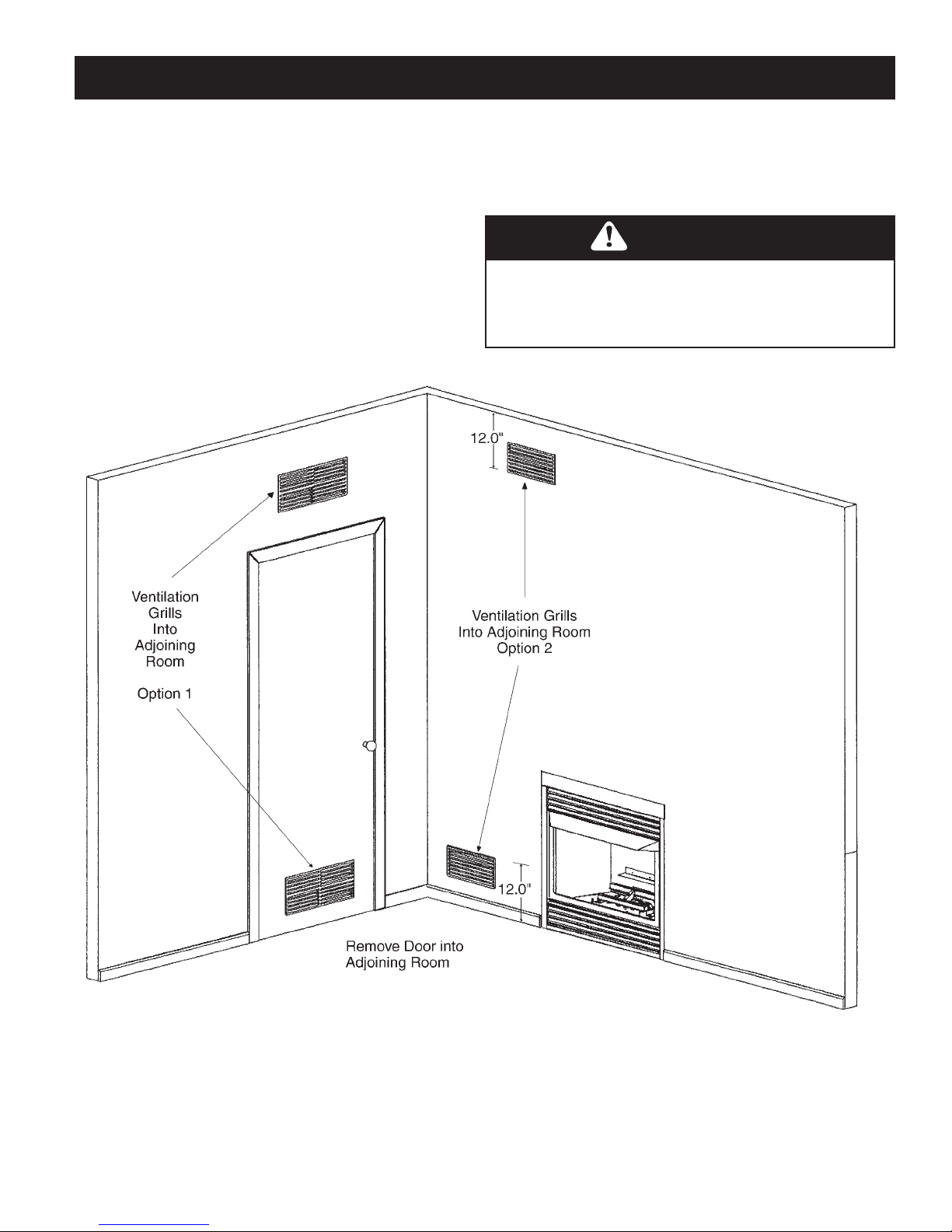
VENTILATION AIR FROM INSIDE BUILDING
This fresh air would come from an adjoining unconfined space. When ventilating to an adjoining unconfined space, you
must provide two permanent openings: one within 12” of the ceiling and one within 12” of the floor on the wall connecting
the two spaces. You can also remove door into adjoining
room. Follow the National Fuel Gas Code NFPA 54/ANSI
Z223.1, Section 5.3, Air for Combustion and Ventilation for
required size of ventilation grills or ducts.
FIGURE 5 - Ventilation Air from Inside Building
WARNING
Rework worksheet, adding the space of the adjoining
unconfined space. The combined spaces must have
enough fresh air to supply all appliances in both spaces.
9
Page 10

AIR FOR COMBUSTION AND VENTILATION Cont.
Ventilation Air From Outdoors
Provide extra fresh air by using ventilation grills or ducts. You must provide two permanent openings: one within 12” of the
ceiling and one within 12” of the floor. Connect these items directly to the outdoors or spaces open to the outdoors. These
spaces include attics and crawl spaces.
IMPORTANT: Do not provide openings for inlet or outlet air into attic if attic has a thermostat-controlled power vent.
Heated air entering the attic will activate the power vent.
FIGURE 6 - Ventilation Air from Outdoors
10
Page 11

INSTALLING – Clearances
11
INSTALLATION
CLEARANCES (VENT
FREE APPLICATION
ONLY)
Minimum noncombustible material above
fireplace opening must be no less than
shown in the figures above.
Noncombustible materials (slate, marble,
tile, etc.) must be at least 1/2” thick, if
sheet metal is used, you must have a noncombustible material behind it.
IMPORTANT: If these minimum clearances are not possible or if local codes do
not permit vent-free operation, you must
operate the heater with the damper open.
Fr ont width Back Width Height Depth
For 18” LOGS 22" 19" 18-3/4" 12-1/2"
For 24” LOGS 29” 22 1/2” 18 3/4” 12 1/2”
For 30” LOGS 38” 28” 18 3/4” 13 1/2”
Minimum Firebox
Width
Minimum Firebox
Depth
FIGURE 6 – Installation Clearances
Minimum Fireplace Dimensions
FIGURE 7 – Mantel Clearances.
Page 12

INSTALLING
12
INSTALLATION OF GLVF24 INTO
EXISTING FIREPLACE
If installing in Canada or as a vented logset:
NOTE: When used as a vented heater, appliance must be
installed only in a solid fuel burning fireplace with a working
flue and constructed of non-combustible material. See chart
below for minimum permanent flue opening you must
provide. The damper must be secured so the minimum flue
opening will be maintained at all times. This can be done
by removing the damper or welding the damper open.
Chimney Height Minimum Permanent Flue Opening
(feet) (square inches)
6’ - 15’ 39 square inches
15’ - 30’ 29 square inches
Area of Various Standard Round Flues
Diameter (inside) Area (square inches)
5” 20 square inches
6” 29 square inches
7” 39 square inches
8” 51 square inches
WARNING
Before installing in a solid fuel burning fireplace, the
chimney flue and firebox must be cleaned of soot,
creosote, ashes, and loose paint by a qualified chimney
cleaner. Creosote may ignite when heated to a high
temperature. Have chimney flue inspected for damage.
If flue system is damaged, you may close the damper if
using as a vent-free system. If you are using the burner
as a vented burner and the flue system is damaged, do
not install the unit.
WARNING
Seal any fresh air vents or ash cleanout doors located
on the floor or wall of fireplace. If this is not done,
drafting may result causing pilot outage or sooting. Use
a heat-resistant sealant. Do not seal chimney flue
damper.
FIGURE 8 – Installing GLVF24 into existing fireplace.
Page 13

INSTALLING – Gas Line
13
INSTALLING GAS LINE
Early signs of carbon monoxide poisoning resemble the flu,
with headaches, dizziness, and / or nausea. If you have these
signs, the heater may not be working properly. Get fresh air at
once! Turn off gas appliance. Have appliance serviced. Some
people (such as pregnant women, persons with heart or lung
disease, persons with anemia and those at high altitudes) are
more affected by carbon monoxide than others. Make
certain you read and understand all warnings. Place Burner
Base / Grate Assembly in center of firebox and connect
flexible gas line to incoming black iron pipe gas line.
Do not connect appliance before pressure testing gas piping.
Damage to gas valve may result and an unsafe condition may
be caused.
Prepare incoming black iron gas line with Teflon tape or pipe
joint compound (check with local codes about the use of
Teflon tape). Compounds used on threaded joints of gas piping
shall be resistant to the action of Liquefied Petroleum (LP or
Propane) and should be applied lightly to ensure excess sealant
does not enter the gas line.
Complete your gas installation by connecting incoming gas line
to regulator. Secure all joints tightly with wrench but do not
over-tighten. If a flexible gas line is used, take care not to kink
connector. The burner pressure is controlled by the
(cont’d. on next page )
DANGER
CARBON MONOXIDE POISONING
MAY LEAD TO DEATH!
WARNING
Any changes to this heater or its controls can be
dangerous.
NOTICE
Installation and repair should be done by a qualified
service person well trained in the installation of such
appliances. You will also need a building permit from
your local Building Commissioner before installing this
appliance, otherwise your insurance company may not
cover this appliance.
FIGURE 9, 9a – Gas line and manual shutoff valve
Page 14

INSTALLING – Gas Line Cont.
14
CAUTION
Any safety screen or guard removed for servicing an
appliance must be replaced prior to operating the heater.
regulator. Check pressure at the pressure test point, which is
located on the side of the gas control near the pilot outlet.
Make sure that the pressure tap is completely closed after
checking gas pressure. The pressure should be checked with
the appliance burning and the control set on high.
IMPORTANT: Loosen the pipe adapter on the flex tube
before installing to the system piping.
NOTICE
A qualified gas appliance installer must connect the
fireplace to the gas supply. Consult all local codes.
CAUTION
Use new black pipe only. Internally tinned copper
tubing can be used in some areas when permitted by
local codes. Only use pipe of 1/2” or greater diameter
to allow full gas volume to heater. Excessive pressure
loss will occur if the pipe is too small.
A manual shutoff valve, union and plugged
pressure tap pointer must be installed upstream of the
heater.
A sediment trap must be installed upstream of the heater
to prevent moisture and contaminants from passing
through the pipe to the heater controls and burners. Failure
to do so could prevent the heater from operating
reliably.
1
⁄8” NPT
CHECK GAS TYPE: The gas supply must be the same as
stated on the heater’s rating plate. If the gas supply is
different, Do Not Install the heater. Contact your dealer for
the correct model.
CAUTION
All gas piping and connections must be tested for leaks
after installation is completed. To test, turn gas valve on,
then apply a soap and water solution to all connections
and joints. If bubbles appear, leak can be detected and
corrected. Never use an open flame for leak testing.
Never operate any appliance if a leak is detected!
For the state of Massachusetts a T-handle gas shut-off
valve must be used on a gas appliance. This T-handle gas
shut-off valve must be listed and approved by the state of
Massachusetts. This is in reference to the state of
Massachusetts state code CMR238.
Page 15

INSTALLING – Burner System
15
CLEANING AND SERVICING OF BURNER / ODS PILOT
It is recommended to annually inspect and clean the unit to prevent malfunction and / or sooting. This operation should
be performed by your dealer or a qualified technician.
Remove log set, handling carefully by holding gently at each
end. (Refer to Log Placement section.) Gloves are
recommended to prevent skin irritation from ceramic.
Annual Cleaning / Inspection
• Do not use cleaning fluids to clean logs or any part of the
heater.
• Use a soft bristle brush or a vacuum with brush attachment.
• Vacuum loose particles and dust from burner ports, valve
and blower compartments.
• Vacuum any accumulation of lint from primary mixing
tube.
• Inspect ODS pilot for operation, accumulation of lint at the
air inlet holes.
• Verify flame pattern and log placement for proper
operation.
• Verify that all ports ignite and cross over smoothly from rear
to front burner.
WARNING
Turn off heater and allow to cool before cleaning. Only
a qualified service technician should service and repair
appliance.
WARNING
Failure to keep primary air openings clear, may result in
sooting and property damage.
CAUTION
Never use a wire, needle, or similar object to clean
ODS / Pilot. This can damage ODS / Pilot.
FIGURE 10 – ODS Pilot, both manual and Millivolt pilot flames shown
FIGURE 11 – Standing Pilot
Page 16

INSTALLING – Log Grate
16
ATTACHING LOG GRATE TO
FIREPLACE BASE
WARNING
1. Position log grate into fireplace and mark screw locations
on each side of mounting bracket.
2. Remove grate assembly, drill 2 holes at the marked
locations.
3. Attach grate assembly to fireplace base. (Screws not
provided.)
4. Connect to gas supply.
INSTALLATION OF LOGF24
LOGSET
1. Place main log on locating pins on burner grate bottom.
2. Place crossover log on locating pins on top of rear main
log.
3. Position front log flat surface up to main log.
➃
➁
You must secure this heater to fireplace base, or heater
will move when you adjust controls. Moving heater
may cause a gas leak and may result in property damage or personal injury.
WARNING
Failure to position the parts in accordance with the
diagrams or failure to use only parts specifically
approved with this heater may result in property
damage or personal injury.
➀
Kingsman Replacement Log Listing
Reference Part
Number Number Description
1 24F-A Front Main Log A, LOGF24
➂
FIGURE 12 – Log Placement
2 24F-B Rear Main Log B, LOGF24
3 24F-C Front Log C, LOGF24
4 24F-D Crossover Log D, LOGF24
WARNING
The positioning of the logs is critical for the safe and clean operation of this heater. Sooting and other problems can
occur if the logs are not properly and firmly positioned in the heater. Never add additional logs or embellishments such
as pine cones,vermiculite, volcanic rock or rock wool to the heater.
Page 17

Step (3) Locate hole on the underside of Log D. Place log over front
17
burner and locator pin then lower into position (as illustrated).
Log Locator pin
Step (1) Remove logs from carton and inspect each log.
Burner
Burner
Assembly base
Log Locator pin
LOGF18 PLACEMENT GUIDELINES
Rear Log Holder
Step (4) Using Log B, place flat surface of the log onto burner assembly base.
Push log up to Log C & D.
Step (2) Locate hole on the underside of Log C. Place log over front
burner and locator pin then lower into position (as illustrated).
Page 18

Step (5) Place log A onto rear log holder and pull up to log C & D.
LOGF18 PLACEMENT GUIDELINES (continued)
18
Page 19

Rear Log Holder
Step (1) Remove logs from carton and inspect each log.
Burner
Log locator pin
Burner Assembly
base
Step (2) Place front main log A on log locator pins.
Retainer pin
Step (3) Position rear main log B onto rear log holder located on rear of firebox.
Position locking tabs of rear main log B into locking tabs of front main log A.
Step (4) Place crossover log D onto the retainer pins located on the
top of rear main log B.
LOGF24 PLACEMENT GUIDELINES
19
Page 20

Step (5) Place Log C onto front burner.
LOGF24 PLACEMENT GUIDELINES (continued)
20
Page 21

LOGF30 Log Installation
Log Locator
Tab
Log Support
Original Log
Locator Pin
21
1. Align front hole of log support plate with original log locator pin.
2. Slide log support over pin & using two 10-24 DT screws, mount plate to burner grate.
NOTE: Make sure log support is tight against side of burner grate before fastening.
Page 22

Step (4) Place left front log by positioning the slot (located on the
bottom of log) with log retainer tab and lower into position.
Step (5) Place right front log by positioning the slot (located on
bottom of log) with log retainer tab and lower into position.
22
When using the LOGF30 log, you must attach the 30 inch log supports
found in the log set.
Step (1) Align front hole of 30 inch log support plate with original log locator pin.
Step (2) Slide the 30 inch log support over log locator pin. Using two 6-32 x 5/16
screws, mount plate to burner grate. NOTE: Make sure log support is tight
against side of burner grate before fastening.
LOGF30 PLACEMENT GUIDELINES
Grate Bars
30 inch Log support
Log
Locator
tabs
Log locator pin
Rear log holder
Step (3) Place front log by positioning the notches
on the underside of the front log with the grate bars
and pull forward.
Page 23

Step (6) Place rear log onto the rear log holder and pull up to the left and
23
Step (8) Line up right crossover log with locator pins and lower into position.
right front logs.
LOGF30 PLACEMENT GUIDELINES (continued)
Complete LOGF30 Logset.
Step (7) Line up left crossover log with locator pins and lower into position.
Page 24

24
Millivolt System, Lighting, and Burner Control
FOR YOUR SAFETY READ BEFORE LIGHTING
WARNING: If you do not follow these instructions exactly, a fire or explosion may result causing property
damage, personal injury or loss of life.
A This appliance has a pilot which must be lighted by hand. When
lighting the pilot, follow these instructions exactly.
B Smell all around the appliance area for gas. Be sure to smell next
to the floor because some gas is heavier than air and will settle on
the floor.
WHAT TO DO IF YOU SMELL GAS
Do not try to light an appliance.
Do not touch any electrical switch; do not use any phone in your
building.
LIGHTING INSTRUCTIONS
1. Stop! Read the safety information above this label.
2. Set the thermostat to lowest setting.
3. Turn off all electrical power to the appliance.
4. Locate valve under the burner assembly.
5. If the control knob is not already in the off position, i.e. the word
“OFF” in the 9 o’clock position, then push in the gas control knob
slightly and turn clockwise to “OFF”. NOTE: Knob cannot be
turned from “PILOT” to “OFF” unless knob is pushed in slightly. Do
not use force.
6. Wait five [5] minutes to clear out any gas. If you then smell gas.
STOP! Follow “B” in the safety information above on this label. If
you don’t smell gas then go to the next step.
7. Now push in the control knob slightly and turn counter-clockwise
to the “PILOT” position.
8. Push in the control knob all the way and hold it. With the other
hand push in the red igniter button until you hear a click. Now
observe closely the pilot burner located on the rear center-left
hand side of the main burner.
TO TURN OFF THE APPLIANCE
1. Set the thermostat to lowest setting.
2. Turn off all electric power to the appliance if service is to be
performed.
3. Open the control access door.
NOTE: Only one on/off device (manual on/off, remote control, or hard wired thermostat) should be connected to the
appliance at any one time, this is most important when installing an insert or stove as the on/off rocker switch is installed at
the factory.
BEFORE LIGHTING
Immediately call your gas supplier from a neighbour’s phone. Follow the
gas supplier’s instructions.
If you cannot reach your gas supplier, call the fire department.
C Use only your hand to push or turn the gas control knob. Never use
tools. If the knob will not push in or turn by hand, don’t try to repair it.
Call a qualified technician. Force or attempted repair may result in a fire
or explosion.
D Do not use the appliance if any part has been under water. Immediately
call a qualified service technician to inspect the appliance and to
replace any part of the control system which has been under water.
If a flame has appeared then continue to depress the control knob for 20
seconds. If the flame did not appear then continue to depress the red
igniter button every 5 seconds until a flame is established. NOTE: If
after 30 seconds a flame has not yet been established then turn the
control knob back to the off position and repeat steps 5, 6 & 7.
9. Once the pilot has been established hold the control knob in the
depressed position for approximately 25 seconds before releasing. If
the flame goes out then repeat steps 7 and 8.
If the knob does not pop up when released, stop and immediately call
your service technician or gas supplier.
If the pilot will not stay lit after several tries, turn the gas control to
“OFF” and call your service technician.
10. Now turn the control knob to the “ON” position. The burner will not light
unless the wall switch thermostat or remote control is turned “ON” or in
the case of the thermostat there is a call for heat.
11. Close the access door and turn all electrical power back to the
appliance.
12. The pilot must be turned off when the unit is not in use.
4. Push in the gas control knob slightly and turn clockwise to the “OFF”
position. Do not force.
5. Replace control access panel.
Recommended Maximum Lead Length (Double Wire)
When Using Wall Switch or Thermostat
Wire Size Max. Length
14ga 100ft [30.4m]
16ga 64ft [19.5m]
18ga 40ft [12.1m]
20ga 25ft [7.6m]
22ga 15ft [4.5m]
CAUTION: DO NOT WIRE 120V POWER TO
MILLIVOLT SWITCHES OR THERMOSTAT.
*In the U.S.A. Thermostats are not permitted for Vented Gas Fireplaces (ANSI Z21.50b-2009 -Decorative).
To Wall Switch,
Thermostat*, Or
Remote Receiver
Page 25

Parts List GLVF24MVN / GLVF24MVP
No.
GLVF24MVN
GLVF24MVP
Description
1.
4200-132
4200-132
Burner Hold Down
2.
24GL-200A
24GL-200A
Burner Assembly
3.
33VF-113
33VF-113
Oxygen Depletion
Shield
4.
33VF-P8214
33VF-P8214
ODS Pilot
5.
33VF-106
33VF-106
Pilot Bracket
6.
33VF-P316VE
33VF-P316VE
Alt Tubing 3/16”
7.
33VF-P683VE
33VF-P683VE
Connector 3/16”
8.
33VF-P245M
N/A
Regulator
9.
33VF-P603VE
33VF-P603VE
Compression
Sleeve 3/16”
10.
33VF-P613VE
33VF-P613VE
Compression Nut
3/16”
11.
33VF-P316VE
33VF-P316VE
Alt Tubing 3/16”
12.
39ZVFCV105A
39ZVFCV105A
Burner Pan
Assembly
No.
GLVF24MVN
GLVF24MVP
Description
13.
39ZVFCV-113
39ZVFCV-113
Valve Bracket
Spacer
14.
6000-112
6000-112
Valve Bracket
15.
1000-214
1000-214
Piezo-Igniter
16.
1000-255
1000-255
Burner Orifice
17.
1000-253
1000-253
Closed Nipple
18.
2000-213
2000-213
Elbow 1/8”
19.
1000-P203VE
1000-P203VE
Lock Nut 1/8”
20.
6000-P113VE
6000-P113VE
Nipple 1/8” x 11/2”
21.
3100-P466A
3100-P466A
1/8”FIPT x 3/8”
Flare
22.
33VF-P637SI
33VF-P637SI
ODS Valve
23.
3632HBP496C
3632HBP496C
3/8” PT-OD Elbow
24.
350-P375D
350-P375D
3/8” Flex – 9”
2 1 3
4
5
14
15
12
18
13
22
16
17
19
20
21
24
23 8 6
11 7 9-10
25
Page 26

Parts List GLVF24MAN / GLVF24MAP
No.
GLVF24MAN
GLVF24MAP
Description
1.
4200-132
4200-132
Burner Hold Down
2.
24GL-200A
24GL-200A
Burner Assembly
3.
33VF-113
33VF-113
Oxygen Depletion
Shield
4.
33VF-P8213
33VF-P8213
ODS Pilot
5.
33VF-106
33VF-106
Pilot Bracket
6.
33VF-P316VE
33VF-P316VE
Alt Tubing 3/16”
7.
33VF-P603VE
33VF-P603VE
Compression
Sleeve 3/16”
8.
33VF-P613VE
33VF-P613VE
Compression Nut
3/16”
9.
39ZVFCV105A
39ZVFCV105A
Burner Pan
Assembly
10.
39ZVFCV-115
39ZVFCV-115
Valve Bracket
11.
33VF-P295M
33VF-P297M
Regulator
12.
33VF-P112VE
33VF-P112VE
Nipple 3/8” x 11/2”
13.
33VF-P124VE
33VF-P124VE
Street 3⁄8 x 45
14.
1001-P100C
1001-P100C
3/8” 90 FPT
15.
1000-255
1000-255
Burner Orifice
No.
GLVF24MAN
GLVF24MAP
Description
16.
1000-253
1000-253
Closed Nipple
17.
2000-213
2000-213
Elbow 1/8”
18.
6000-P113VE
6000-P113VE
1/8 x 1-1/2 Nipple
19.
1000-P203VE
1000-P203VE
Lock Nut 1/8”
20.
3100-P466A
3100-P466A
1/8”FIPT x 3/8”
Flare
21.
33VF-P522SI
33VF-P522SI
ODS Valve
22.
350-P375D
350-P375D
3/8” Flex – 9”
23.
4000-P963VE
4000-P963VE
3/8 OD 3/8 MPT
2 1 3
4
5
15 9 18
10
11
12
16
19
14
21
23
13
7-8
6
17
20
22
26
Page 27

TROUBLESHOOTING
27
WARNING
NOTE: all troubleshooting items are listed in order of
operation.
Turn off and let cool before servicing. Only a qualified
service person should service and repair heater.
When igniter button is pressed, there is no spark at ODS/Pilot.
Possible Cause
1. Igniter electrode positioned wrong.
2. Igniter electrode is broken.
3. Igniter electrode not connected to igniter cable.
4. Igniter cable pinched or wet.
5. Piezo-igniter nut is loose.
6. Broken igniter cable.
7. Bad piezo-igniter.
Remedy
1. Replace igniter.
2. Replace igniter.
3. Reconnect igniter cable.
4. Free igniter cable if pinched by any metal or tubing.
Keep igniter cable dry.
5. Tighten nut.
6. Replace igniter cable.
7. Replace piezo-igniter.
Appliance produces unwanted odors.
Possible Cause
1. Appliance burning vapors from paint, hair spray,
glues, etc.
2. Gas leak.
Remedy
1. Ventilate room. Stop using odor-causing products
while heater is running
2. Locate and correct all leaks.
Appliance shuts off in use.
Possible Cause
1. Not enough fresh air is available for ODS/pilot
to operate.
2. Low line pressure.
3. ODS/pilot is partially clogged.
Remedy
1. Open window and/or door ventilation.
2. Contact local gas company.
3. Clean ODS/pilot.
Gas odor even when control knob is in OFF position.
Possible Cause
1. Gas leak.
2. Control valve defective.
Remedy
1. Locate and correct all leaks.
2. Replace control valve.
When igniter button is pressed, there is a spark at ODS/pilot,
but no ignition.
Possible Cause
1. Gas supply turned off or manual shutoff valve closed.
2. Control knob not in PILOT position.
3. Control knob not pressed in while in PILOT position.
4. Air in gas lines when installed.
5. ODS/pilot is clogged.
6. Gas regulator setting is not correct.
Remedy
1. Turn on gas supply or open manual shutoff valve.
2. Turn control knob while in PILOT position.
3. Press control knob in while in PILOT position.
4. Continue holding down control knob. Repeat igniting
operation until air is removed.
5. Replace ODS/pilot assembly or get it serviced.
6. Replace gas regulator.
ODS/pilot lights, but flame goes out when control knob is released.
Possible Cause
1. Control knob not fully pressed in.
2. Control knob not pressed in long enough.
3. Manual shutoff valve not fully open
4. Thermocouple connection loose at valve.
Remedy
1. Press control knob in fully.
2. After ODS/pilot lights, keep control knob pressed in
for 30 seconds.
3. Fully open manual shutoff valve.
4. Hand tighten until snug, then tighten 1/4 turn more.
Page 28

TROUBLESHOOTING Cont.
28
5. Pilot flame not touching thermocouple, which allows
thermocouple to cool, causing pilot flame to go out.
Problem could be caused by one or both of the following:
A) Low gas pressure
B) Dirty or partially clogged ODS/pilot.
6. Thermocouple damaged.
7. Control valve damaged.
5. Contact local gas company.
6. Replace thermocouple
7. Replace control valve.
One or both burners do not light after ODS/pilot is lit.
Possible Cause
1. Burner orifice is clogged.
2. Burner orifice diameter is too small.
3. Inlet pressure is too low.
Remedy
1. Clean burner or replace light burner orifice.
2. Replace burner orifice.
3. Contact qualified service person.
Delayed ignition of burner.
Possible Cause
1. Manifold pressure is too low.
2. Burner orifice is clogged.
Remedy
1. Contact local gas company.
2. Clean burner or replace burner orifice.
Burner backfiring during combustion.
Possible Cause
1. Burner orifice is clogged or damaged.
2. Burner is damaged.
3. Gas regulator is defective.
Remedy
1. Clean burner or replace burner orifice.
2. Replace burner.
3. Replace Gas regulator.
Slight smoke or odor during initial operation.
Possible Cause
1. Vapors from paint or curing process of logs.
Remedy
1. Problem will stop after a few hours of operation. Run
the heater with the damper open if you have one or open
a window for the first few hours.
Log appears to smoke (after initial operation).
Possible Cause
Remedy
1. Log heater is intended to be smokeless. Turn off heater
and call qualified service person.
Heater produces a whistling noise when burner is lit.
Possible Cause
1. Turning control knob to HI position when burner is cold.
2. Air in gas line.
3. Dirty or partially clogged burner orifice.
Remedy
1. Turn control knob to LO position and let warm up for a
minute
2. Operate burner until air is removed from line. Have gas
line checked by local gas company.
3. Clean burner or replace burner orifice.
No Gas to pilot.
Possible Cause
1. LP regulator shut down due to inlet pressure being
too high.
Remedy
1. Verify LP tank regulator is installed and set at 11 to 13
inches w.c.
2. Replace LP regulator on heater.
Page 29

Model No.
Serial No.
Date installed
Dealer or Contractor Name:
The Ultimate in Design, Engineering & Quality
29
This Limited Lifetime Warranty applies only while the unit remains at the site of the original installation
and only if the unit is installed inside the continental United States, Alaska, Hawaii, and Canada. The
warranty applies only if the unit is installed and operated in accordance with the printed instructions and
in compliance with applicable installation and building codes and good trade practices.
BASIC ONE YEAR WARRANTY
During the first year after installation, we will provide a replacement for any component part of your unit found to be defective in
materials or workmanship, including labour costs. Repair work requires prior approval by Kingsman, labour costs are based on a
predetermined rate schedule and any repair work must be done through an authorized Kingsman dealer.
(Excluded Components: Accent Light Bulbs, Gasketing and Paint)
LIMITED LIFETIME WARRANTY
The heat exchanger, combustion chamber and burner of every Kingsman product excluding the Outdoor Firepit are warranted against
materials or workmanship during the period the product is owned by the original owner. The part to be replaced must be returned to our
distributor in exchange for the replacement part. Any labor, material, freight and/or handling charges associated with any repair or
replacement pursuant to this Limited Lifetime Warranty will not be covered by this warranty.
GENERAL TERMS
In lieu of providing a replacement part, we may, at our option, provide the distributor's component purchase price from us or a credit
equal to the distributor’s component purchase price from us toward the purchase of any new unit which we distribute. If a credit is given
in lieu of a replacement part, the rating plate from the unit being replaced must be submitted on a warranty claim, and the u nit being
replaced must be made available to our distributor for disposition.
In establishing the date of installation for any purpose, including determination of the starting date for the term of this Limited Lifetime
Warranty, reasonable proof of the original installation date must be presented*, otherwise the effective date will be based upon the date
of manufacture plus thirty (30) days.
We will not be responsible for and you, the user, will pay for: (a) damages caused by accident, abuse, negligence, misuse, ri ot, fire,
flood, or Acts of God (b) damages caused by operating the unit where there is a corrosive atmosphere containing chlorine, fluorine, or
any other damaging chemicals (other than in a normal residential environment) (c) damages caused by any unauthorized alteration or
repair of the unit affecting its stability or performance (d) damages caused by improper matching or application of the unit or the unit's
components (e) damages caused by failing to provide proper maintenance and service to the unit (f) any expenses incurred for
erecting, disconnecting or dismantling the unit (g) parts or supplies used in connection with service or maintenance (h) damage repairs,
inoperation or inefficiency resulting from faulty installation or application (i) electricity or fuel costs or any increase in electricity or fuel
cost whatsoever including additional or unusual use of supplemental electric heat.
We shall not be liable for any incidental, consequential, or special damages or expenses in connection with any use or failur e of this
unit. We have not made and do not make any representation or warranty of fitness for a particular use or purpose, and there is no
implied condition of fitness for a particular use or purpose. We make no express warranties except as stated in this Limited Lifetime
Warranty. No one is authorized to change this Limited Lifetime Warranty or to create for us any other obligation or liability in
connections with this unit. Any implied warranties shall last for one year after the original installation. Some states and provinces do not
allow the exclusion or limitation of incidental or consequential damages or do not allow limitations on how long an implied warranty or
condition lasts, so the above limitations or exclusions may not apply to you. The provisions of this limited warranty are in additions to
and not a modification of or subtraction from any statutory warranties and other rights and remedies provided by law.
Save this certificate. It gives you specific legal rights, and you may also have other rights which may vary from state to state and
province to province.
In the event your unit needs servicing, contact your dealer or contractor who installed or serviced your unit. When requesting service,
please have the model and serial number from each unit readily available. If your dealer needs assistance, the distributor is available
for support and we, in turn support the distributor's efforts.
Fill in the installation date and model and serial numbers of the unit in the space provided below and retain this limited wa rranty for your
files.
*To receive advantage of your warranty, you must retain the original records that can establish the installation date of your unit.
 Loading...