

Kingsman GLMVF40MVN, VFBL4040MVN, MVFBL4040MVP, MVFBR4040MVN, GLMVF40MVP Owner's Operation And Installation Manual
...Page 1
1
Owner’s Operation and Installation Manual
MVF40 certified as a Universal Firebox ANSI Z21.91-2007
Listed Certified for USA
UNVENTED (VENT-FREE) MULTI-SIDED FIREBOX
Enclosure For Gas-Fired Decorative Type Unvented Room Heaters
Vent Free: GLMVF40MVN, GLMVF40MVP
MVFBL4040MVN, MVFBL4040MVP, MVFBR4040MVN, MVFBR4040MVP
Vent-free: Certified to USA standards: ANSI Z21.11.2 - 2007
Warning
If the information in this manual is not followed
exactly, a fire or explosion my result causing property
damage, personal injury, or loss of life.
– Do not store or use gasoline or other flammable vapors and
liquids in the vicinity of this or any other appliance.
– WHAT TO DO IF YOU SMELL GAS
• Do not try to light any appliance.
• Do not touch any electrical switch; do not use any phone in
your building.
• Immediately call your gas supplier from a neighbor’s
phone. Follow the gas supplier’s instructions.
• If you cannot reach your gas supplier, call the fire
department.
– Installation and service must be performed by a qualified
installer, service agency, or the gas supplier.
Warning
Improper installation, adjustment,
alteration, service, or maintenance
can cause injury or property
damage. Refer to this manual for
correct installation and operational
procedures. For assistance or
additional information consult a
qualified installer, service agency, or
the gas supplier.
Warning
This is an unvented gas-fired heater.
It uses air (oxygen) from the room in
which it is installed. Provisions for
adequate combustion and ventilation
air must be provided. Refer to section
Save this manual for future reference • 2340 Logan Ave., Winnipeg, MB, Canada, Phone: (204) 632-1962 • Printed in Canada • PART #40VF-MAN
July 27, 2009
Warning
Carefully review the instructions
supplied with the decorative type
unvented log set room heater for the
minimum size requirement.
DO NOT INSTALL THE APPLIANCE
IN THIS FIREBOX UNLESS THIS
FIREBOX MEETS THE MINIMUM
DIMENSIONS REQUIRED FOR THE
INSTALLATION
Warning
FOR USE ONLY WITH
A LISTED GAS-FIRED UNVENTED
DECORATIVE ROOM HEATER
NOT TO EXCEED
40,000 BTU/H.
DO NOT BUILD A WOOD FIRE
This appliance must be
installed by a licensed
plumber or gas fitter in
the Commonwealth of
Massachusetts and meet
the requirements of 527
CMR 30 and 248 CMR.
INSTALLER: Leave this manual with the appliance.
CONSUMER: Retain this manual for future reference.
Page 2
2
Page 3

3
Why does my fireplace or stove give off odour?
It is normal for your fireplace to give off some odour. This is due to the curing of the paint, adhesives,
silicones and any undetected oil from the manufacturing process as well as the finishing materials used
with the installations (e.g. marble, tile and the adhesives used to adhere this product to the walls can react
with heat and cause odours).
It is recommended that you burn your gas fireplace or stove for a minimum of four hours at a time with
the fan off after the curing of the paint has been completed. These odours can last upward to 40 hours of
burn time, keep burning at a minimum of four hours per use until odours dissipate.
About curing of the paint
Your stove or fireplace has been painted with the highest quality silicone stove paint. This paint dries
quickly in 15-20 minutes when first applied at the factory. However, due to the high temperature silicone
components, the paint will cure when heat is applied to the appliance as it is first used.
The following information applies to the curing process to get the paint fully hard and durable.
Fire the appliance four successive times for 10 minutes each firing and a 5 minute cool down between
each. Be aware during log and firebox paint curing that a white deposit may be developing on the inside
of the glass doors. It is important to remove this white deposit from the glass doors with an appropriate
cleaner to prevent build-up (such as Windex or a commercial fireplace glass cleaner).
• Babies, small children, pregnant women and pets should leave the area during the cure phase.
• Ventilate well, open doors and windows.
• Do not touch during curing.
Noise coming from the fireplace?
• Noise caused by metal expanding and contracting as it heats up and cools down, similar to the sound
produced by a furnace or heating duct. This noise does not affect the operation or longevity of your
fireplace.
• Different types and thicknesses of steel will expand and contract at different rates resulting in
“cracking” and “ticking” sounds throughout the heating and cooling periods.
• You should also be aware that as temperatures change within the unit these sounds will likely reoccur. Again this is normal for steel fireboxes, and is not a defect.
Cleaning the Glass
During the first few fires, a white film may develop on the glass front, as part of the curing process. The
glass should be cleaned after the unit has cooled down or the film can bake on and become very difficult
to remove. Use a non-abrasive cleaner and do not attempt to clean the glass while it is hot.
PRE-INSTALLATION QUESTIONS and ANSWERS
Page 4

4
TABLE OF CONTENTS
SECTION PAGE
Burner System Options . . . . . . . . . . . . . . . . . . . . . . . . . . . . . . . . . . . . . . . . . . . . . . . . . . . . . . . . . . . . . . . . . . . . . . . .5
Safety Information . . . . . . . . . . . . . . . . . . . . . . . . . . . . . . . . . . . . . . . . . . . . . . . . . . . . . . . . . . . . . . . . . . . . . . . . . . . .6
Local Codes . . . . . . . . . . . . . . . . . . . . . . . . . . . . . . . . . . . . . . . . . . . . . . . . . . . . . . . . . . . . . . . . . . . . . . . . . . . . .7
For Your Safety Read Before Lighting . . . . . . . . . . . . . . . . . . . . . . . . . . . . . . . . . . . . . . . . . . . . . . . . . . . . . . . .7
Framing Specifications . . . . . . . . . . . . . . . . . . . . . . . . . . . . . . . . . . . . . . . . . . . . . . . . . . . . . . . . . . . . . . . . . . . . . . . . 8
Framing Parts . . . . . . . . . . . . . . . . . . . . . . . . . . . . . . . . . . . . . . . . . . . . . . . . . . . . . . . . . . . . . . . . . . . . . . . . . . . . .9-10
Dimensions . . . . . . . . . . . . . . . . . . . . . . . . . . . . . . . . . . . . . . . . . . . . . . . . . . . . . . . . . . . . . . . . . . . . . . . . . . . . . . . .11
Installing . . . . . . . . . . . . . . . . . . . . . . . . . . . . . . . . . . . . . . . . . . . . . . . . . . . . . . . . . . . . . . . . . . . . . . . . . . . . . . . . . . 12
Installation Clearances . . . . . . . . . . . . . . . . . . . . . . . . . . . . . . . . . . . . . . . . . . . . . . . . . . . . . . . . . . . . . . . . . . . 13
Installing by Framing Fireplace . . . . . . . . . . . . . . . . . . . . . . . . . . . . . . . . . . . . . . . . . . . . . . . . . . . . . . . . . . . . 14
Peninsula Framing . . . . . . . . . . . . . . . . . . . . . . . . . . . . . . . . . . . . . . . . . . . . . . . . . . . . . . . . . . . . . . . . . . . . . . 16
See-Through Framing . . . . . . . . . . . . . . . . . . . . . . . . . . . . . . . . . . . . . . . . . . . . . . . . . . . . . . . . . . . . . . . . . . .17
Bay Peninsula Framing . . . . . . . . . . . . . . . . . . . . . . . . . . . . . . . . . . . . . . . . . . . . . . . . . . . . . . . . . . . . . . . . . . .18
Corner Framing . . . . . . . . . . . . . . . . . . . . . . . . . . . . . . . . . . . . . . . . . . . . . . . . . . . . . . . . . . . . . . . . . . . . . . . . .19
Universal Firebox . . . . . . . . . . . . . . . . . . . . . . . . . . . . . . . . . . . . . . . . . . . . . . . . . . . . . . . . . . . . . . . . . . . . . . .20
Air for Combustion and Ventilation . . . . . . . . . . . . . . . . . . . . . . . . . . . . . . . . . . . . . . . . . . . . . . . . . . . . . . . . . . . . .21
Providing Adequate Ventilation . . . . . . . . . . . . . . . . . . . . . . . . . . . . . . . . . . . . . . . . . . . . . . . . . . . . . . . . . . . .21
Determining Air Flow for Firebox Location . . . . . . . . . . . . . . . . . . . . . . . . . . . . . . . . . . . . . . . . . . . . . . . . . . .21
Ventilation Air from Inside Building . . . . . . . . . . . . . . . . . . . . . . . . . . . . . . . . . . . . . . . . . . . . . . . . . . . . . . . .23
Ventilation Air from Outdoors . . . . . . . . . . . . . . . . . . . . . . . . . . . . . . . . . . . . . . . . . . . . . . . . . . . . . . . . . . . . .24
Installing Gas Line . . . . . . . . . . . . . . . . . . . . . . . . . . . . . . . . . . . . . . . . . . . . . . . . . . . . . . . . . . . . . . . . . . . . . . . . . . .25
Installing MVFB 4040 Burner System . . . . . . . . . . . . . . . . . . . . . . . . . . . . . . . . . . . . . . . . . . . . . . . . . . . . . . . . . . .26
Cleaning and Servicing of Burner /ODS Pilot . . . . . . . . . . . . . . . . . . . . . . . . . . . . . . . . . . . . . . . . . . . . . . . . .26
Installing MVFB4040 Burner System & LOGF38 . . . . . . . . . . . . . . . . . . . . . . . . . . . . . . . . . . . . . . . . . . . . . . . . . .27
LOGF38 Log Placement for MVFB4040 Burner System . . . . . . . . . . . . . . . . . . . . . . . . . . . . . . . . . . . . . . . . . .28-29
Installing GLMVF40 Burner System . . . . . . . . . . . . . . . . . . . . . . . . . . . . . . . . . . . . . . . . . . . . . . . . . . . . . . . . . . . .30
LOGC31 Log Placement for GLMVF40 Burner Grate . . . . . . . . . . . . . . . . . . . . . . . . . . . . . . . . . . . . . . . . . . . .31-32
Millivolt System, Lighting Instructions & Burner Control . . . . . . . . . . . . . . . . . . . . . . . . . . . . . . . . . . . . . . . . . . . .33
Installing Fan Kit, Screen Door, Shield + Hood . . . . . . . . . . . . . . . . . . . . . . . . . . . . . . . . . . . . . . . . . . . . . . . . .34-35
Illustrated Parts List . . . . . . . . . . . . . . . . . . . . . . . . . . . . . . . . . . . . . . . . . . . . . . . . . . . . . . . . . . . . . . . . . . . . . . .36-38
Accessory and Parts List . . . . . . . . . . . . . . . . . . . . . . . . . . . . . . . . . . . . . . . . . . . . . . . . . . . . . . . . . . . . . . . . . . .39-40
Troubleshooting . . . . . . . . . . . . . . . . . . . . . . . . . . . . . . . . . . . . . . . . . . . . . . . . . . . . . . . . . . . . . . . . . . . . . . . . . .41-42
Warranty . . . . . . . . . . . . . . . . . . . . . . . . . . . . . . . . . . . . . . . . . . . . . . . . . . . . . . . . . . . . . . . . . . . . . . . . . . . . . . . . . . .43
Page 5
5
BURNER SYSTEM OPTIONS
See chart below for required burner system:
TABLE 1 - The MVF40 is also approved as a Universal Vent Free Box. See page 20 for more information.
MVF40 Vent Free Firebox Required burner system: (Select from below to complete the fireplace)
OPTION 2
MVFBL/R 40 Burner Systems - control are hidden and accessed through bottom grill.
LOGF38 Log Set Fibre Five Piece - Required for MVFBL/R 4040 Burner Systems
Burner Model Valve Type Fuel Type BTU – Input Min/Max Inlet Manifold Pressure Orifice Size Primary Air
Left Hand Burner
MVFBL4040MVN Millivolt Natural Gas 26,000-38,000 5.5/10” 1.6-3.5” 32 0.25
MVFBL4040MVP Millivolt Liquid Propane 26,000-34,000 11/13” 6.3-10” 50 Full Open
Right Hand Burner
MVFBR4040MVN Millivolt Natural Gas 26,000-38,000 5.5/10” 1.6-3.5” 32 0.25
MVFBR4040MVP Millivolt Liquid Propane 26,000-34,000 11/13” 6.3-10” 50 Full Open
OPTION 1
GLMVF40 Log Grate Burner System - controls are accessed from firebox on raised grate. Pull screen are recommended.
LOGC31 Log Set 7 Piece required for GLMVF40 Burner Systems.
Burner Model Valve Type Fuel Type BTU – Input Min/Max Inlet Manifold Pressure Orifice Size Primary Air
GLMVF40MVN Millivolt Natural Gas 29,900-38,225 5.5/10” 1.6-3.5” 32 1/8” Open
GLMVF40MVP Millivolt Liquid Propane 24,200-30,500 11/13” 6.3-10” 49 1/2” Open
This appliance is equipped for (Natural or Propane) Gas.
Field conversion is not permitted.
Page 6
SAFETY INFORMATION WARNINGS
6
WARNINGS
Important: Read this owner’s manual carefully and completely
before trying to assemble, operate, or service this firebox.
Improper use of this firebox can cause serious injury or death
from burns, fire, explosion, electrical shock, and carbon monoxide
poisoning.
Early signs of carbon monoxide poisoning resemble the
flu, with headaches, dizziness, and / or nausea. If you have these
signs, the heater may not be working properly. Get fresh air at
once! Turn off gas appliance. Have appliance serviced. Some
people (such as pregnant women, persons with heart or lung
disease, persons with anemia and those at high altitudes) are more
affected by carbon monoxide than others. Make certain you read
and understand all warnings.
1. Use correct gas type for your appliance. Do not convert from
one gas type to another.
2. If this appliance is for use with Propane gas, do not place
propane supply tank(s) inside any structure. Locate propane
supply tank(s) outdoors.
3. If you smell gas:
– Shut off gas supply.
– Do not try to light any appliance.
– Do not touch any electrical switch; do not use any phone in
your building.
– Immediately call your gas supplier from a neighbor’s
phone. Follow the gas supplier’s instructions.
– If you cannot reach your gas supplier, call the fire
department.
4. Do not use this appliance for burning trash or cooking. Never
place matches, paper, garbage, or any other material on top
of logs or logs into flame.
5. Warning: Always operate appliance with front fireplace
screens closed.
6. Make sure any safety screen or guard removed for servicing
is in place before running appliance.
7. Never run appliance in a small, closed room. Open the door
into next room to help ventilate.
8. If appliance shuts off, do not relight until you provide fresh
outside air. If appliance keeps shutting off, have it serviced.
9. Do not run appliance:
– where flammable liquids or vapors are used or stored.
– under dusty conditions.
10. Surface of appliance becomes very hot when operating. Keep
children and adults away from hot surface. Appliance will
remain hot for some time after shutdown. Allow surface to
cool before touching.
11. Do not use this appliance if any part has been submerged
under water. Immediately call a qualified technician to
inspect the appliance and to replace any part of the control
system and gas control which has been under water.
12. The installation must conform with local codes or, in the absence
of local codes, with the National Fuel Gas Code, ANSI Z223.1.
13. Never install the appliance:
– in a bedroom, bathroom, mobile home, or recreational
vehicle.
– where curtains, furniture, clothing, or other flammable
objects are less than forty-two inches (42”) from the front
of the appliance.
– in high traffic areas.
– in windy or drafty areas.
14. Disconnect the appliance and its individual shut off valve
from the gas supply piping system during any pressure
testing of that system at test pressures in excess of 1/2 psig,
(3.5kPa).
15. Isolate the appliance from the gas supply piping system by
closing its individual manual shut off valve during any
pressure testing of the the gas supply piping system at test
pressure equal or less than 1/2 psig,(3.5kPa).
16. Do not use any type of after-market blower that fits inside the
fireplace. Drafts created by these type of blowers may cause
sooting.
17. Turn off appliance and let cool before servicing. Only a
qualified service person should install, service and repair
appliance
DANGER
CARBON MONOXIDE POISONING
MAY LEAD TO DEATH!
NOTE: It is recommended that a Carbon Monoxide (CO)
Detector be installed in or near bedrooms and on all levels of
your home. Place a detector about 15 feet (4.5 meters) outside
the room that houses your gas appliance.
This appliance is equipped for
(Natural or Propane) Gas.
Field conversion is not permitted.
Warning: Failure to position parts in accordance
with these diagrams or failure to use only part
specifically approved with this heater may result in
property damages or personal injury.
Page 7
7
WARNING
If you do not follow these instructions exactly, a fire or
explosion may result causing property damage,
personal injury or loss of life.
18. Inspect the appliance before use and at least annually by a professional service person. Frequent cleaning may be required due to
excessive lint from carpeting, bedding material, etc. It is important that control compartment, burner and circulating air passage of
the appliance be kept open.
19. When operated for the first time, there will be some smell from the appliance. This will diminish and disappear after a few hours of
operation.
20. Warning: Do not allow fans to blow directly into the fireplace. Avoid any drafts that alter flame patterns.
21. Warning: Do not use a blower insert, heat exchanger insert or other accessory not approved for use with this heater.
22. The firebox canopy must not be replaced with a canopy which may be provided with the decorative type UNVENTED room heater.
23. Warning: Do not operate ceiling fans in same room as the vent free appliance.
24. Due to high temperatures, the appliance should be located out of traffic and away from furniture and draperies.
25. Children and adults should be alerted to the hazard of high surface temperature and should stay away to avoid burns or clothing
ignition.
26. Young children should be carefully supervised when they are in the same room with the appliance.
27. Do not place clothing or other flammable material on or near the appliance.
28. Any safety screen or guard removed for servicing an appliance must be replaced prior to operating the heater (see 1.2.3).
29. Installation and repair should be done by a qualified service person. The appliance should be inspected before use and at least
annually by a professional service person. More frequent cleaning may be required due to excessive lint form carpeting, bedding
material, etc. It is imperative that control compartments, burners and circulating air passageways of the appliance be kept clean.
30. “Warning: Any change to this heater or its controls can be dangerous.”
31. Must be installed by a licensed gasfitter in the Commonwealth of Massachusetts. Complies to code 527 CMR
32. Unvented gas fired appliances may be used only for supplemental heat and/or decorative purposes and under no
circumstances shall they provide a primary heat source.
33.
Warning: Failure to keep the primary air opening(s) of the burner(s) clean may result in sooting and property damage.
LOCAL CODES
Install and use fireplace with care. Follow all local codes.
In the absence of local codes, use the latest edition of
The National Fuel Gas Code ANSI Z223.1, also known as
NFPA 54*. Firebox must be electrically grounded in
accordance with the National Electrical Code,
ANSI/NFPA 70 (latest edition).
*Available from:
American National Standards Institute, Inc. National Fire Protection Association, Inc.
1430 Broadway Batterymarch Park
New York, NY 10018 Quincy, MA 02260
FOR YOUR SAFETY READ BEFORE LIGHTING
A. This appliance has a pilot which must be lighted by hand. When lighting the pilot, follow these instructions exactly.
B. Before lighting, smell all around the appliance area for gas. Be sure to smell next to the floor because some gas is
heavier than air and will settle on the floor.
What to do if you smell gas
• Do not try to light any appliance.
• Do not touch any electric switch; do not use any phone in your building.
• Immediately call your gas supplier from a neighbor’s phone. Follow the gas supplier’s instructions.
• If you cannot reach your gas supplier, call the fire department.
C. Use only your hand to push in or turn the gas control knob. Never use tools. If the knob will not push in or turn by hand,
don’t try to repair it, call a qualified service technician or gas supplier. Force or attempted repair may result in a fire or
explosion.
D. Do not use this appliance if any part has been under water. Immediately call a qualified service technician to inspect the
appliance and to replace any part of the control system and any gas control which has been under water.
Page 8
8
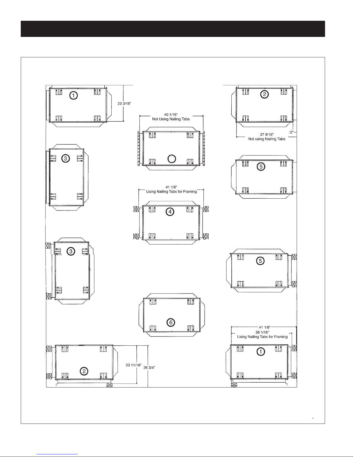
FRAMING SPECIFICATIONS
See Page 9 for required parts for installation.
FIGURE 1
Framing Clearances to Fireplace:
Bottom – 0 / Sides – 0 to standoffs / Top – 0 to standoffs / Adjacent side wall – 2” / Front of fireplace to ceiling – 41”.
Right Corner Top View
Without 2 x 4 Framing
Left Corner Top View
using 2 x 4 Framing
See Thru top View
Without 2 x 4 Framing
See Thru Top View using
2 x 4 Framing
Island Top View
PLACEMENT AND FRAMING
Note: When not using nailing tabs
you may place Heatshield directly
against existing wall and screw
unit to the floor using holes located
in the bottom of unit
Bay Peninsula
without
2 x 4 Framing
Bay Peninsula
Using 2 x 4
Framing
Right Corner Top View
Using 2 x 4 Framing
Peninsula Top View
Using 2 x 4 Framing
Peninsula Top View
Without 2 x 4 Framing
Left Corner Top View
Without 2 x 4 Framing
4
Page 9

9
FRAMING PARTS
REQUIRED PARTS FOR INSTALLATIONS OF MULTI-SIDED FIREPLACE
MVF40 Multi-Sided Vent Free Firebox
Choose Your installation (as shown on Page 8, and see below for required parts.)
1. RIGHT CORNER INSTALLATION
MVF40CK Corner Kit - One Large Side Open, One Small Side Open
Choose Natural Gas or Liquid Propane Burner:
Choose Grill Kits or Panel Kits:
MGCKBP Grill Kit Corner - Classic Polish Brass (Two Sets)
MGCKBA Grill Kit Corner - Classic Antique Brass (Two Sets)
MGCKBC Grill Kit Corner - Classic Chrome (Two Sets)
MGCKBL Grill Kit Corner - Black (Two Sets)
MGCKPB Grill Kit Corner - Polish Brass (Two Sets)
MGCKAB Grill Kit Corner - Antique Brass (Two Sets)
MGCKCR Grill Kit Corner - Chrome (Two Sets)
MVF40PCK Panel Kit for Corner Kit - Black (Two Sets)
2. LEFT CORNER INSTALLATION
MVF40CK Corner Kit - One Large Side Open, One Small Side Open
Choose Natural Gas or Liquid Propane Burner:
Choose Grill Kits or Panel Kits:
MGCKBP Grill Kit Corner - Classic Polish Brass (Two Sets)
MGCKBA Grill Kit Corner - Classic Antique Brass (Two Sets)
MGCKBC Grill Kit Corner - Classic Chrome (Two Sets)
MGCKBL Grill Kit Corner - Black (Two Sets)
MGCKPB Grill Kit Corner - Polish Brass (Two Sets)
MGCKAB Grill Kit Corner - Antique Brass (Two Sets)
MGCKCR Grill Kit Corner - Chrome (Two Sets)
MVF40PCK Panel Kit for Corner Kit - Black (Two Sets)
BURNER SYSTEM & LOG SET (REQUIRED FOR MVF40 FIREBOX)
OPTION 1
GLMVF40MVN Vent Free Multiview Burner System – Millivolt Valve 38,000 BTU/HR Natural Gas
GLMVF40MVP Vent Free Multiview Burner System – Millivolt Valve 35,000 BTU/HR Liquid Propane
LOGC31 Log Set LOGC31 required for GLMVF40 Burner System
OPTION 2
MVFBL4040MVN Vent Free Left Burner System – Millivolt Valve 38,000 BTU/HR Natural Gas
MVFBL4040MVP Vent Free Left Burner System – Millivolt Valve 35,000 BTU/HR Liquid Propane
LOGF38 Log Set required for MVFB40 R/L Burner System
This appliance is equipped for (Natural or Propane) Gas.
Field conversion is not permitted.
BURNER SYSTEM & LOG SET (REQUIRED FOR MVF40 FIREBOX)
OPTION 1
GLMVF40MVN Vent Free Multiview Burner System – Millivolt Valve 38,000 BTU/HR Natural Gas
GLMVF40MVP Vent Free Multiview Burner System – Millivolt Valve 35,000 BTU/HR Liquid Propane
LOGC31 Log Set LOGC31 required for GLMVF40 Burner System
OPTION 2
MVFBR4040MVN Vent Free Right Burner System – Millivolt Valve 25,900/38,225 Natural Gas
MVFBR4040MVP Vent Free Right Burner System – Millivolt Valve 24,200/30,500 Liquid Propane
LOGF38 Log Set required for MVFB40 R/L Burner System
Page 10

10
FRAMING PARTS (continued)
3. BAY PENINSULA INSTALLATION
MVF40BK Bay Peninsula Kit - One Large Side Open, Two Small Sides Open
Choose Natural Gas or Liquid Propane Burner:
Choose Grill Kits or Panel Kits:
MGBKBP Grill Kit Bay Peninsula - Classic Polish Brass (Three Sets)
MGBKBA Grill Kit Bay Peninsula - Classic Antique Brass (Three Sets)
MGBKBC Grill Kit Bay Peninsula - Classic Chrome (Three Sets)
MGBKBL Grill Kit Bay Peninsula - Black (Three Sets)
MGBKPB Grill Kit Bay Peninsula - Polish Brass (Three Sets)
MGBKAB Grill Kit Bay Peninsula - Antique Brass (Three Sets)
MGBKCR Grill Kit Bay Peninsula - Chrome (Three Sets)
MVF40PBK Panel Kit Bay Peninsula Kit - Black (Three Sets)
4. SEE-THROUGH INSTALLATION
MVF40SK See Through Kit - Two Large Sides Open
Choose Natural Gas or Liquid Propane Burner:
Choose Grill Kits or Panel Kits:
MGSKBP Grill Kit See-Through - Classic Polish Brass (Two Sets)
MGSKBA Grill Kit See-Through - Classic Antique Brass (Two Sets)
MGSKBC Grill Kit See-Through - Classic Chrome (Two Sets)
MGSKBL Grill Kit See-Through - Black (Two Sets)
MGSKPB Grill Kit See-Through - Polish Brass (Two Sets)
MGSKAB Grill Kit See-Through - Antique Brass (Two Sets)
MGSKCR Grill Kit See-Through - Chrome (Two Sets)
MVF40PSK Panel Kit See-Through - Black (Two Sets)
BURNER SYSTEM & LOG SET (REQUIRED FOR MVF40 FIREBOX)
OPTION 1
GLMVF40MVN Vent Free Multiview Burner System – Millivolt Valve 38,000 BTU/HR Natural Gas
GLMVF40MVP Vent Free Multiview Burner System – Millivolt Valve 35,000 BTU/HR Liquid Propane
LOGC31 Log Set LOGC31 required for GLMVF40 Burner System
OPTION 2
MVFBR4040MVN Vent Free Right Burner System – Millivolt Valve 25,900/38,225 Natural Gas
MVFBR4040MVP Vent Free Right Burner System – Millivolt Valve 24,200/30,500 Liquid Propane
MVFBL4040MVN Vent Free Left Burner System – Millivolt Valve 38,000 BTU/HR Natural Gas
MVFBL4040MVP Vent Free Left Burner System – Millivolt Valve 35,000 BTU/HR Liquid Propane
LOGF38 Log Set required for MVFB40 R/L Burner System
Page 11

11
5. PENINSULA INSTALLATION
MVF40PK Peninsula Kit - Two Large Sides Open, One Small Side Open
Choose Natural Gas or Liquid Propane Burner:
Choose Grill Kits or Panel Kits:
MGPKBP Grill Kit Peninsula - Classic Polish Brass (Three Sets)
MGPKBA Grill Kit Peninsula - Classic Antique Brass (Three Sets)
MGPKBC Grill Kit Peninsula - Classic Chrome (Three Sets)
MGPKBL Grill Kit Peninsula - Black (Three Sets)
MGPKPB Grill Kit Peninsula - Polish Brass (Three Sets)
MGPKAB Grill Kit Peninsula - Antique Brass (Three Sets)
MGPKCR Grill Kit Peninsula - Chrome (Three Sets)
MVF40PPK Panel Kit Peninsula - Black (Three Sets)
6. ISLAND INSTALLATION
MVF40IK Island Kit - Four Sides Open
Choose Natural Gas or Liquid Propane Burner:
Choose Grill Kits or Panel Kits:
MGIKBP Grill Kit Island - Classic Polish Brass (Four Sets)
MGIKBA Grill Kit Island - Classic Antique Brass (Four Sets)
MGIKBC Grill Kit Island - Classic Chrome (Four Sets)
MGIKBL Grill Kit Island - Black (Four Sets)
MGIKPB Grill Kit Island - Polish Brass (Four Sets)
MGIKAB Grill Kit Island - Antique Brass (Four Sets)
MGIKCR Grill Kit Island - Chrome (Four Sets)
MVF40PIK Panel Kit Island Kit - Black (Four Sets)
Required For all Burners
LOGF38 Log Set - Five Piece Fibre Split Oak - For MVFB40 Burners
LOGC31 Log Set - Seven Piece - For GLMVF40 Burners
*Note that we suggest Left Burner as your first choice, you can choose a Right Burner if a (*) is notated beside part number
FRAMING PARTS (continued)
BURNER SYSTEM & LOG SET (REQUIRED FOR MVF40 FIREBOX)
OPTION 1
GLMVF40MVN Vent Free Multiview Burner System – Millivolt Valve 38,000 BTU/HR Natural Gas
GLMVF40MVP Vent Free Multiview Burner System – Millivolt Valve 35,000 BTU/HR Liquid Propane
LOGC31 Log Set LOGC31 required for GLMVF40 Burner System
OPTION 2
MVFBR4040MVN Vent Free Right Burner System – Millivolt Valve 25,900/38,225 Natural Gas
MVFBR4040MVP Vent Free Right Burner System – Millivolt Valve 24,200/30,500 Liquid Propane
MVFBL4040MVN Vent Free Left Burner System – Millivolt Valve 38,000 BTU/HR Natural Gas
MVFBL4040MVP Vent Free Left Burner System – Millivolt Valve 35,000 BTU/HR Liquid Propane
LOGF38 Log Set required for MVFB40 R/L Burner System
Page 12
12
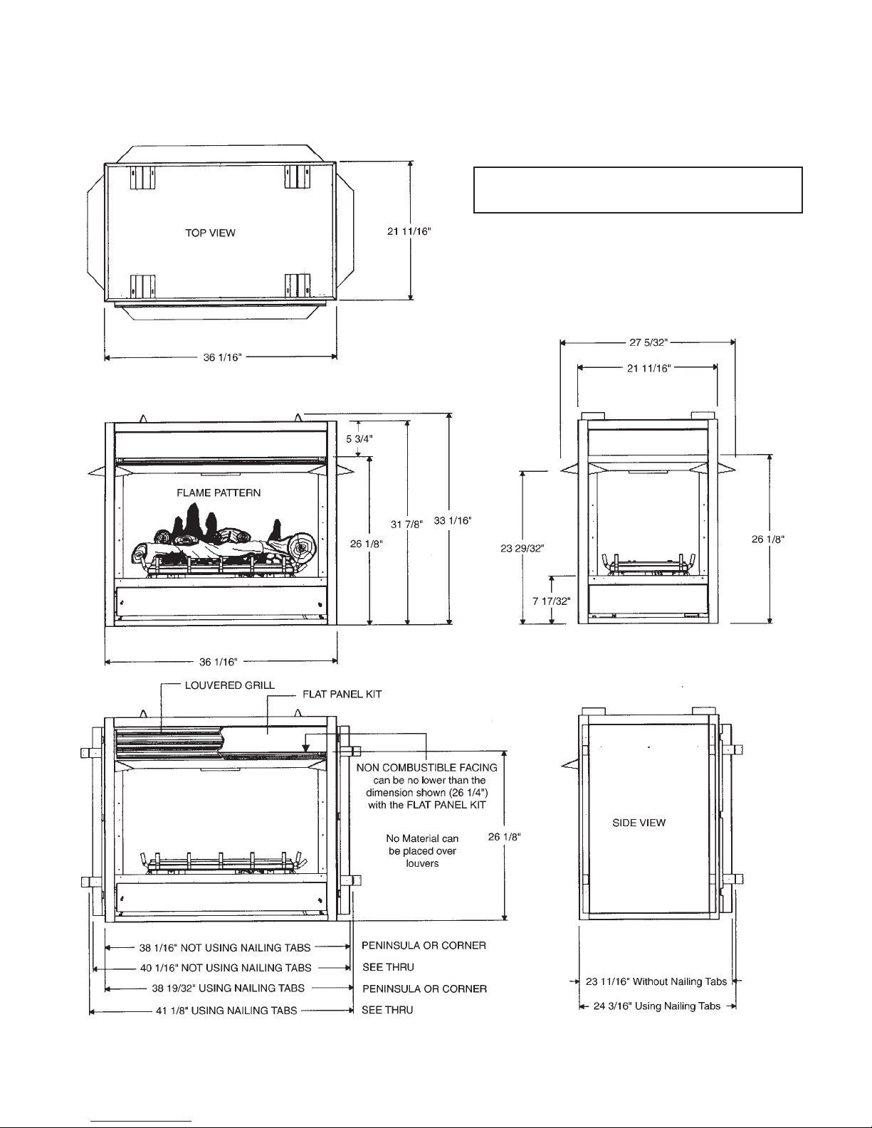
NOTE: Non combustible materials such as tile, marble,
and brick may overlap any facing on the appliance, but
should never cover any necessary openings like
louvered grills.
WARNING: Do not allow any combustible materials
to overlap the firebox front facing.
DIMENSIONS
FIGURE 2
Page 13
13
INSTALLING – Clearances
IMPORTANT: Vent-free gas log heaters add moisture to
the air. Although this is beneficial, installing firebox in
rooms without enough ventilation air may cause mildew to
form from too much moisture. See Air for Combustion and
Ventilation, pages 20 through 23.
IMPORTANT: Make sure the firebox is level.
If firebox is not level, log set will not work properly
.
INSTALLATION CLEARANCES
Carefully follow the instructions below. This will
ensure safe installation.
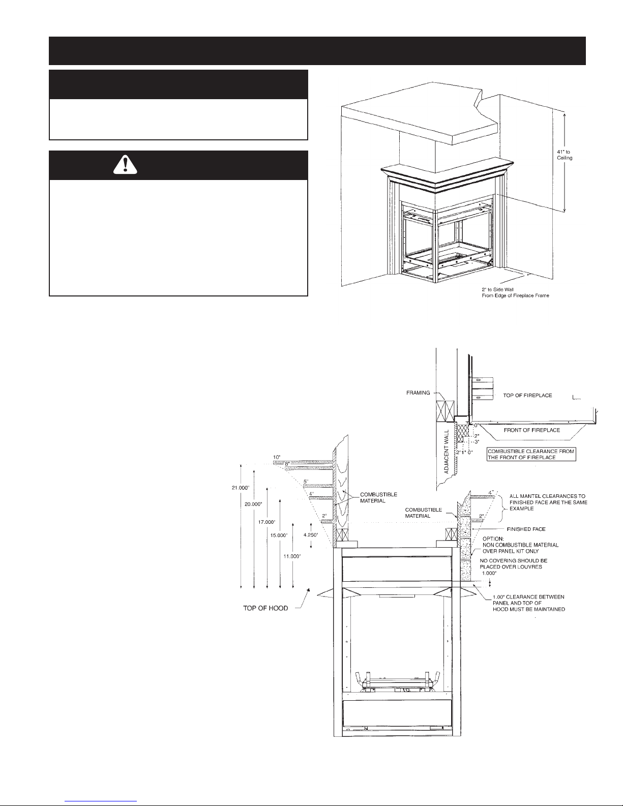
Minimum Wall and Ceiling Clearances
A. Clearances from the firebox to
adjacent wall should not be less than
2 inches. (Ref. Page 8)
B. Clearance from the top of the
fireplace front to the ceiling should
not be less than 41 inches.
C.
Clearance from the bottom of firebox
to the floor is 0 inches. Bottom of unit
must be flush with top of combustible
floor covering.
D. Clearance from side of fireplace to
enclosure is 0 inches.
E. Clearance from top of fireplace
standoffs is 0 inches.
F. Clearance from opens side of fireplace
is 36”.
These fireboxes can be installed as freestanding
units against a wall with the approved, optional
cabinet mantels or as a built-in unit. The
clearances are the same for either installation method.
NOTICE
A qualified service person must install firebox. Follow
all local codes.
WARNING
Never install the firebox
• in a bedroom or bathroom
• in a recreational vehicle
• where curtains, furniture, clothing, or other
flammable objects are less than 36 inches from the
front, top, or sides of the firebox
• in high traffic areas
• in windy or drafty areas
FIGURE 3 – Minimum Clearances - Top and Sides
of Room Heater to Ceiling and Walls.
FIGURE 4 – Mantel Clearances.
Page 14

14
INSTALLING – Framing
INSTALLING BY FRAMING
FIREPLACE
Built-in installation of this firebox involves installing firebox
into a framed-in enclosure. Optional brass trim accessories are
available. The brass trim will extend past sides of firebox.
This will cover the rough edges of the wall opening. If
installing a mantel above the firebox, you must follow the
clearances shown in Figure 4, page 12. Follow the instructions
below to install the firebox in this manner
.
1. Frame in rough opening. The firebox framing should be
constructed of 2 x 4 lumber or heavier. Use dimensions in
Figure 1, 2 ,3 and 4, pages 8, 10 and 11. Adjust framing
so that firebox is flush with finished wall surface.
2.
Install gas piping to firebox location. See Installing Gas
Line on page 24 and Connecting to Gas Supply in log set
owners manual. IMPOR
TANT: If installing blower
accessory see page 31.
3.
Carefully insert firebox into rough opening.
4. Attach firebox to wall studs using nails or wood screws
through holes in nailing flange.
5. If using optional Brass Surround Kit, install the trim after
final finishing and/or painting of wall. See instructions
included with brass trim accessory for attaching Surround.
6. Install and properly test gas log heater. Follow installation
instructions included with the vent-free gas log heater that
is being installed.
IMPORTANT: When finishing your firebox, combustible
materials such as wall board, gypsum board, sheet rock,
drywall, plywood, etc. may be butted up next to the sides and
top of the firebox. Combustible materials should never overlap
the firebox front facing.
IMPORTANT: Non-combustible materials such as brick, tile,
etc. may overlap the front facing, but should never cover any
necessary openings like louvered slots.
CAUTION
Log heaters installed in this firebox create warm air
currents. These currents move heat to wall surfaces next
to firebox. Installing firebox next to vinyl or cloth wall
coverings or operating firebox where impurities in the
air (such as tobacco smoke) exist, may discolor walls.
WARNING
Do not allow any materials to overlap the firebox front
facing.
WARNING
Never modify or cover the louvered slots on the front
of the firebox.
WARNING
Use only non-combustible mortar or adhesives when
overlapping the front facing with non-combustible
facing material.
WARNING
Do not allow non-combustible materials to cover any
necessary openings like louvered slots.
CAUTION
Do not install the firebox on carpet or vinyl.
WARNING
Maintain the minimum clearances. If you can, provide
greater clearances from floor, ceiling, and adjoining wall.
WARNING
Ensure the minimum clearances shown in Figures 3 and
4 on page 12 are maintained. Left and right clearances
are determined when facing the front of the heater
.
Page 15

15
INSTALLING – Mantel Cabinets
NOTICE
A qualified service person must install firebox. Follow
all local codes.
NOTICE
Installation and repair should be done by a qualified
service person well trained in the installation of such
appliances. You will also need a building permit from
your local Building Commissioner before installing this
appliance, otherwise your insurance company may not
cover this appliance.
DANGER
CARBON MONOXIDE POISONING
MAY LEAD TO DEATH!
WARNING
Any changes to this heater or its controls can be
dangerous.
CAUTION
Use new black pipe only. Internally tinned copper
tubing can be used in some areas when permitted by
local codes. Only use pipe of 1/2” or greater diameter
to allow full gas volume to heater. Excessive pressure
loss will occur if the pipe is too small.
A manual shutoff valve, union and plugged
1
⁄8” NPT
pressure tap pointer must be installed upstream of the
heater.
A sediment trap must be installed upstream of the heater
to prevent moisture and contaminants from passing
through the pipe to the heater controls and burners. Failure
to do so could prevent the heater from operating
reliably.
Page 16

16
PENINSULA FRAMING SPECIFICATIONS
FRAMING
Using 2x4s frame to local building codes.
DO NOT install against a vapour barrier or
exposed insulation.
Framing measurements have been adjusted to
accommodate a 1/2” thick finished wall.
FIGURE 5.
Combustible materials may be installed flush
with top and sides of fireplace.
It is not necessary to install a hearth with this
fireplace system. Objects placed in front of
the fireplace should be kept a minimum of
24” away from the front face.
Gas line installation should be performed
only after Fireplace installation. Fireplace
bottom supplies you with two 6”x8”
rectangular holes. The use of these holes
depends on valve and Fireplace location on
riser or upper floor.
NOTE
If the unit is installed in a non conventional manner not using
2x4 framing the nailing tabs may be removed and the heat
shields may be placed directly against a combustible wall or
partition.
When the unit is installed without nailing tabs the unit must
be secured to the floor using the holes located in the bottom
of the fireplace.
FIREPLACE ASSEMBLY
1. Mount Door Cover on one end. Figure #6.
Position Door Cover over opening as shown
in diagram and using 4 self tapping screws
secure onto fireplace. Check to see that door
cover is properly sealed.
2. Hang Heat Shield on top edge of
Fireplace and secure with self tapping
screws. Heat Shield must be centered
allowing a 1/2” clearance both sides of
Fireplace for finishing material.
3. The heat shield is equipped with nailing
tabs if 2x4 framing is used as shown in
diagram Level Fireplace and nail or screw
into place.
When not using 2x4 framing secure Unit
with screws at bottom (SEE ABOVE
NOTE:)
Note: Framing dimension shown is to accept
1/2” Facing Material. The dimension shown may
be reduced depending on the thickness of
facing material up to 1”
Figure 6
Figure 5
Screw Attachment
Points (4)
NOTE: The standoffs are non load bearing. When
installing a cabinet, a maximum weight of 250 lbs
can be installed on the 1/2” drywall lip (located
around the perimeter of the appliance).
Page 17

17
SEE-THROUGH FRAMING SPECIFICATIONS
FRAMING
Using 2x4s frame to local building codes.
DO NOT install against a vapour barrier or exposed insulation.
Framing measurements have been adjusted to accommodate a
1/2” thick finished wall. FIGURE 7.
Combustible materials may be installed flush with top and sides
of fireplace.
It is not necessary to install a hearth with this fireplace system.
Objects placed in front of the fireplace should be kept a minimum
of 24” away from the front face.
Gas line installation should be performed only after Fireplace
installation. Fireplace bottom supplies you with two 6” x 8”
rectangular holes. The use of these holes depends on valve and
Fireplace location on riser or upper floor.
NOTE
If the unit is installed in a non conventional
manner not using 2x4 framing the nailing tabs
may be removed and the Heat Shields may be
placed directly against a combustible wall or
partition.
When the unit is installed without nailing tabs
the unit must be secured to the floor using the
holes located in the bottom of the fireplace.
FIREPLACE ASSEMBLY
1. Mount Door Cover on one end. Figure #8.
Position Door Cover over opening as shown in
diagram and using 4 self tapping screws secure onto
fireplace. Check to see that door cover is properly
sealed.
2. Hang Heat Shield on top edge of Fireplace and
secure with self tapping screws. Heat Shield must be
centered allowing a 1/2” clearance both sides of
Fireplace for finishing material.
3. The Heat Shield is equipped with nailing tabs if
2x4 framing is used as shown in diagram. Level
Fireplace and nail or screw into place.
When not using 2x4 framing secure Unit with screws
at bottom (SEE ABOVE NOTE:)
Figure 7
Figure 8
Page 18

18
BAY PENINSULA FRAMING SPECIFICATIONS
FRAMING
Using 2x4s frame to local building codes.
DO NOT install against a vapour barrier or
exposed insulation.
Framing measurements have been adjusted to
accommodate a 1/2” thick finished wall.
FIGURE 9.
Combustible materials may be installed flush with
top and sides of fireplace.
It is not necessary to install a hearth with this
fireplace system. Objects placed in front of the
fireplace should be kept a minimum of 24” away
from the front face.
Fireplace bottom supplies you with two 6” x 8”
holes. The use of these holes depends on valve and
Fireplace location on riser or upper floor.
NOTE
If the unit is installed in a non conventional manner
not using 2x4 framing the nailing tabs may be
removed and the Heat Shields may be placed
directly against a combustible wall or partition.
When the unit is installed without nailing tabs the
unit must be secured to the floor using the holes
located in the bottom of the fireplace.
FIREPLACE ASSEMBLY
1. To mount Door Cover, Figure #10. Position Door Cover
over opening as shown in diagram and using 6 self tapping
screws secure onto fireplace. Check to see that door cover is
properly sealed.
2. Hang Heat Shield on top edge of Fireplace and secure with
self tapping screws. Heat Shield must be centered allowing a
1/2” clearance both sides of Fireplace for finishing material.
3. The Heat Shield is equipped with nailing tabs if 2x4
framing is used as shown in diagram. Level Fireplace and nail
or screw into place.
When not using 2x4 framing secure Unit with screws at
bottom (SEE ABOVE NOTE:)
NOTE: Use 8-18 x 3/4 DT screws for bottom of door cover.
NOTE: Holes for mounting sides of Heat Shield are not
pre-punched.
Note: Framing dimension shown is to
accept 1/2” facing material. The dimension
shown may be reduced depending on the
thickness of facing material up to 1”
Bay Peninsula Fireplace Shown
Figure 10
Figure 9
NOTE: The standoffs are non load bearing. When
installing a cabinet, a maximum weight of 250 lbs
can be installed on the 1/2” drywall lip (located
around the perimeter of the appliance).
Page 19

19
CORNER FRAMING SPECIFICATIONS
FRAMING
Using 2x4s frame to local building codes.
DO NOT install against a vapour barrier or exposed insulation.
Framing measurements have been adjusted to accommodate a
1/2” thick finished wall. FIGURE 11.
Combustible materials may be installed flush with top and sides
of fireplace.
It is not necessary to install a hearth with this fireplace system.
Objects placed in front of the fireplace should be kept a
minimum of 24” away from the front face.
Fireplace bottom supplies you with two 6” x 8” rectangular
holes. The use of these holes depends on valve and Fireplace
location on riser or upper floor.
NOTE
If the unit is installed in a non conventional
manner not using 2x4 framing the nailing tabs
may be removed and the Heat shields may be
placed directly against a combustible wall or
partition.
When the unit is installed without nailing tabs the
unit must be secured to the floor using the holes
located in the bottom of the fireplace.
FIREPLACE ASSEMBLY
1. Mount Door Cover on one end. Figure #12. Position
Door Cover over opening as shown in diagram and using
4 self tapping screws secure onto fireplace. Check to see
that door cover is properly sealed.
2. Hang Heat Shield on top edge of Fireplace and secure
with self tapping screws. Heat Shield must be centered
allowing a 1/2” clearance both sides of Fireplace for
finishing material.
3. The Heat Shield is equipped with nailing tabs if 2x4
framing is used as shown in diagram. Level Fireplace and
nail or screw into place.
When not using 2x4 framing secure Unit with screws at
bottom (SEE ABOVE NOTE:)
NOTE: Use 8-18 x 3/4 DT screws for bottom of door cover
NOTE: Holes for mounting sides of heat shield are not
pre-punched.
Figure 12
Corner Fireplace Shown
Figure 11
Page 20

20
UNIVERSAL FIREBOX
The MVF40 is approved as a Zero Clearance Universal Firebox, when using as a Universal Firebox the bottom burner pan
must be used. (Part # 38VF-134).
When installing another manufacturer’s log and burner system, follow the manufacturer’s assembly instructions.
For framing, see pages 12 through 18 depending on type of installation. (eg. SEE THRU, ISLAND, PENINSULA, CORNER,
AND BA
Y PENINSULA) Follow all clearances to combustibles in this manual and see below for installation of the Bottom
Firebox Pan (Part # 38VF-134) that must be used.
The Firebox canopy must not be replaced with a canopy which may be provided with the decorative type unvented room heater.
USE ONLY KINGSMAN DECORATIVE COMPONENT AND REPLACEMENT PARTS.
Figure 13
Warning: Fireplace screen must be closed
while appliance is in operation.
Page 21

21
AIR FOR COMBUSTION AND VENTILATION
Today’s homes are built more energy efficient than ever. New materials, increased insulation, and new construction methods
help reduce heat loss in homes. Home owners weather strip and caulk around windows and doors to keep the cold air out
and the warm air in. During heating months, home owners want their homes as airtight as possible.
While it is good to make your home energy
efficient, your home needs to breathe. Fresh air must enter
your home. All fuel-burning appliances need fresh air for
proper combustion and ventilation.
Exhaust fans, fireboxes, clothes dryers, and fuel burning
appliances draw air from the house to operate. You must
provide adequate fresh air for these appliances. This will
insure proper venting of vented fuel-burning appliances.
PROVIDING ADEQUATE VENTILATION
The following are excerpts from National Fuel Gas Code. NFPA 54/ANSI Z223.1, Section 5.3, Air for Combustion and
Ventilation:
All spaces in homes fall into one of the three following ventilation classifications:
1. Unusually Tight Construction, 2. Unconfined Space, 3. Confined Space.
The information on pages 20 through 24 will help you classify your space and provide adequate ventilation.
Unusually T
ight Construction
The air that leaks around doors and windows may provide enough fresh air for combustion and ventilation. However, in
building of usually tight construction, you must provide additional fresh air.
Unusually tight construction is defined as construction where:
a. walls and ceilings exposed to the outside atmosphere have a continuous water vapor retarder with a rating of one
perm (6 x 10-11 per pasec-m2) or less with openings gasketed or sealed and
b. weather stripping has been added on openable windows and doors and
c. caulking or sealants are applied to areas such as joints around window and door frames, between sole plates and
floors, between wall-ceiling joints, between wall panels, at penetrations for plumbing, electrical, and gas lines, and
at other openings.
If your home meets any of the three criteria above, you must provide additional fresh air.
See Ventilation Air From Outdoors, page 24.
Confined and Unconfined Space
The National Fuel Gas Code (ANSI Z223.1, 1992 SEction 5.3) defines a confined space as a space whose volume is less than
50 cubic feet per 1,000 btu per hour (4.8 m3 per kw) of the aggregate input rating of all appliances installed in that space.
Rooms communicating directly with the space in which the appliances are installed*, through openings not furnished with
doors, are considered a part of the unconfined space.
*Adjoining rooms are communicating only if there are doorless passageways or ventilation grills between them.
DETERMINING AIR FLOW FOR FIREBOX LOCATION
Determining if You Have a Confined or Unconfined Space
Use the work sheet on the next page to determine if you have a confined or unconfined space.
Space: Includes the room in which you will install firebox plus any adjoining rooms with doorless
passageways or ventilation grills between the rooms.
WARNING
This firebox shall not be installed in a confined space
unless provisions are provided for adequate combustion
and ventilation air. Read the following instructions to
insure proper fresh air for this and other fuel-burning
appliances in your home.
Page 22

22
AIR FOR COMBUSTION AND VENTILATION Cont.
1. Determine the volume of the space (length x width x height).
Length x Width x Height = ______________ cu. ft. (volume of space)
Example: Space size 22ft. (length) x 18 ft. (width) x 8 ft. (ceiling height) = 3168 cu. ft. (volume of space)
If additional ventilation to adjoining room is supplied with grills or openings, add the volume of these rooms to the total
volume of the space.
2. Divide the space volume by 50 cubic feet to determine the maximum Btu/Hr the space can support.
______________ (volume of space) ÷ 50 cu. ft. = 63.3 or 63,300 (maximum Btu/Hr the space can support)
3. Add the Btu/Hr of all fuel burning appliances in the space.
Vent-free firebox __________________ Btu/Hr
Gas water heater* __________________ Btu/Hr
Gas furnace __________________ Btu/Hr
Vented gas heater __________________ Btu/Hr
Gas firebox logs __________________ Btu/Hr
Other gas appliances* + __________________ Btu/Hr
Total = __________________ Btu/Hr
Example: Gas water heater 40,000 Btu/Hr
Vent-free firebox with log heater + 39,000 Btu/Hr
Total = 79,000Btu/Hr
* Do not include direct-vent gas appliances. Direct-vent draws combustion air from the outdoors and vents to the
outdoors.
4. Compare the maximum Btu/Hr the space can support with the actual amount of Btu/Hr used.
__________________ Btu/Hr (maximum the space can support)
__________________ Btu/Hr (actual amount of Btu/Hr used)
Example: 63,300 Btu/Hr (maximum the space can support)
79,000 Btu/Hr (actual amount of Btu/Hr used)
The space in the above example is a confined space because the actual Btu/Hr used is more than the maximum Btu/Hr the
space can support. You must provide additional fresh air. Your options are a follows:
A. Rework work sheet, adding the space of an adjoining room. If the extra space provides an unconfined space, remove
door to adjoining room or add ventilation grills between rooms, See Ventilation Air from Inside Building, page 22.
B.
Vent room directly to the outdoors. See ventilation Air
from Outdoors, page 23.
C.
Install a lower Btu/Hr firebox, if lower Btu/Hr size
makes room unconfined.
If the actual Btu/Hr used is less than the maximum Btu/Hr
the space can support, the space is an unconfined fined
space. You will need no additional fresh air ventilation.
WARNING
If the area in which the firebox and gas log heater may be
operated is smaller than that defined as an unconfined
space, provide adequate combustion and ventilation air by
one of the methods described in the National Fuel Gas
Code, ANSI Z223.1, 1992, Section 5.3.
Page 23

23
AIR FOR COMBUSTION AND VENTILATION Cont.
VENTILATION AIR FROM INSIDE BUILDING
This fresh air would come from an adjoining unconfined space. When ventilating to an adjoining unconfined space, you
must provide two permanent openings: one within 12” of the ceiling and one within 12” of the floor on the wall connecting
the two spaces. You can also remove doors into adjoining
rooms. Follow the National Fuel Gas Code NFPA 54/ANSI
Z223.1, Section 5.3, Air for Combustion and Ventilation for
required size of ventilation for required size of ventilation
grills or ducts.
WARNING
Rework worksheet, adding the space of the adjoining
unconfined space. The combined spaces must have
enough fresh air to supply all appliances in both spaces.
Ventilation Grills into
adjoining room
Option 1
Ventilation Grills
into adjoining room
Option 2
Remove Door into
adjoining room
Figure 14
Page 24

24
AIR FOR COMBUSTION AND VENTILATION Cont.
Ventilation Air From Outdoors
Provide extra fresh air by using ventilation grills or ducts. You must provide two permanent openings: one within 12” of the
ceiling and one within 12” of the floor. Connect these items directly to the outdoors or spaces open to the outdoors. These
spaces include attics and crawl spaces.
IMPORTANT: Do not provide openings for inlet or outlet air into attic if attic has a thermostat-controlled power vent.
Heated air entering the attic will activate the power vent.
FIGURE 15 - Ventilation Air from Outdoors
Page 25

25
INSTALLING – Gas Line
INSTALLING GAS LINE
Early signs of carbon monoxide poisoning resemble the flu, with
headaches, dizziness, and / or nausea. If you have these signs, the
heater may not be working properly. Get fresh air at once! Turn off
gas appliance. Have appliance serviced. Some people (such as
pregnant women, persons with heart or lung disease, persons with
anemia and those at high altitudes) are more affected by carbon
monoxide than others. Make certain you read and understand all
warnings.Place Burner Base or Grate Assembly in center of firebox
and connect flexible gas line to incoming black iron pipe gas line.
Do not connect appliance before pressure testing gas piping.
Damage to gas valve may result and an unsafe condition may be
caused.
Prepare incoming black iron gas line with Teflon tape or pipe joint
compound (check with local codes about the use of Teflon tape).
Compounds used on threaded joints of gas piping shall be resistant
to the action of Liquefied Petroleum (LP or Propane) and should be applied lightly to ensure excess sealant does not enter the gas line.
Complete your gas installation by connecting incoming gas line to regulator. Secure all joints tightly with wrench but do not over-
tighten. If a flexible gas line is used, take care not to kink connector. The burner pressure is controlled by the regulator. Check pressure
at the pressure test point, which is located on the side of the gas control near the pilot outlet. Make sure that the pressure tap is
completely closed after checking gas pressure. The pressure should be checked with the appliance burning and the control set on high.
IMPORTANT: Loosen the pipe adapter on the flex tube before installing to the system piping.
CHECK GAS TYPE: The gas supply must be the same as stated on the heater’s rating plate. If the gas supply is different, Do Not
Install the heater. Contact your dealer for the correct model.
For the state of Massachusetts a T-handle gas shut-off valve must
be used on a gas appliance. This T-handle gas shut-off valve must
be listed and approved by the state of Massachusetts. This is in
reference to the state of Massachusetts state code CMR238.
CAUTION
All gas piping and connections must be tested for leaks
after installation is completed. To test, turn gas valve on,
then apply a soap and water solution to all connections
and joints. If bubbles appear, leak can be detected and
corrected. Never use an open flame for leak testing.
Never operate any appliance if a leak is detected!
CAUTION
Any safety screen or guard removed for servicing an
appliance must be replaced prior to operating the heater.
FIGURE 16, 16a – Installing gas line and manual shutoff valve
FIGURE 16a – This is one option for installing shutoff
valve. Check local codes for shutoff location regulations.
NOTICE
A qualified gas appliance installer must connect the
fireplace to the gas supply. Consult all local codes.
Page 26

26
FIGURE 18 – Manual and Millivolt Pilot Flames
FIGURE 19 – Millivolt Models
1. Remove the Universal Bottom before installing Kingsman Multiview Burner system by removing 4 screws.
2. Position burner assembly as per unit configuration (eg. left corner, right corner, peninsula, etc.)
3. Tilt burner assembly so valve is at an angle to the fireplace and lower into position.
4. Line the 4 holes on the burner assembly as shown on the diagram with the 4 holes on the fireplace and screw into place
with 1/2” DT Screws.
5. Install log support plates as shown in the lower diagram. (Make sure the log support plate with the cut out is placed on
the side where the ODS Pilot is located.)
NOTE: When installing Burner assembly into a corner installation it is very important that the NON FLAME END of the
burner assembly is facing the side of the enclosure that is built in.
FIREBOX BOTTOM ODS PILOT
LOCATION
NON FLAME END
OF BURNER
ASSEMBLY
(SEE NOTE)
BURNER
INSTALLATION
HOLES
Figure 17
UNIVERSAL
BOTTOM
NOTE: LOG LOCATOR
PIN ORIENTATION
INSTALLING – MVFB4040 Burner Systems
Warning: Failure to position parts in accordance with these diagrams or failure to use only part specifically
approved with this heater may result in property damages or personal injury.
CLEANING AND SERVICING OF
BURNER / ODS PILOT
It is recommended to annually inspect and clean the unit to
prevent malfunction and / or sooting. This operation should
be performed by your dealer or a qualified technician.
1. Remove fireplace hood and screen. (Refer to Installation
of Door Screen and Hood, page 30.)
2.
Remove log set, handling carefully by holding gently at
each end. (Refer to Log Placement, page 26.) Gloves are
recommended to prevent skin irritation from ceramic.
Annual Cleaning / Inspection
•
Do not use cleaning fluids to clean logs or any part of the
heater.
• Use a soft bristle brush or a vacuum with brush attachment.
• Vacuum loose particles and dust from burner ports, valve
and blower compartments.
• Vacuum any accumulation of lint from primary mixing
tube.
• Inspect ODS pilot for operation, accumulation of lint at the
air inlet holes.
• Verify flame pattern and log placement for proper
operation.
• Verify that all ports ignite and cross over smoothly from rear
to front burner.
WARNING
Turn off heater and allow to cool before cleaning. Only a
qualified service technician should service and repair appliance.
Failure to keep primary air openings clear, may result in
sooting and property damage.
Page 27

27
INSTALLING – MVFB4040 Burner Systems and LOGF38
WARNING
The positioning of the logs is critical for the safe
and clean operation of this heater. Sooting and other
problems can occur if the logs are not properly and
firmly positioned in the heater. Never add additional
logs or embellishments such as pine cones, vermiculite,
volcanic rock or rock wool to the heater.
Log Installation
The Kingsman log set has been numbered for ease of installation.
1. Place log #1 onto plate with the ODS Pilot extending through
the notch area. Position holes on under side of Log #1 with the 2
vertical tabs on the plate and lower onto plate.
2. Place log #4 onto plate opposite of plate with the ODS Pilot
3. Position Log #5 onto end Pin of Log #4 as shown in diagram
4. Position Log #3 onto center Pin of Log #4 as shown in diagram.
5. Position log #2 onto Pin of Log #1 and position Log #2 up
against Log #4.
NOTE LOG #5 IS TO BE POSITIONED ON THE NON FLAME SIDE.
Crushed Rock Installation
Place crushed rock onto firebox bottom making sure not to
place any rock onto the burner or burner ports as this will
cause carboning, delayed ignition, and will raise Carbon
Monoxide to very dangerous levels.
Side Brick Panel Installation (Long Side)
1. Remove side brick clip located on top of Firebox.
2. Slide Side Brick Panel into Firebox through the small side
opening and center from left to right and push tight against side
wall of Firebox.
3. Place Brick Clip back into position and tighten
Back Brick Panel Installation (Short Side)
1. Remove back brick clip located on top of Firebox.
2.Slide Back Brick Panel into Firebox through the large side
opening and center form left to right and push tight against side
wall of Firebox.
3. Place Brick Clip Back into position and tighten.
Optional Back and Side Brick Panel Installations
NOTE: BRICK CLIPS CAN BE REPOSITIONED DEPENDING ON TYPE OF INSTALLATION
Figure 21
Figure 20
Page 28

28
Log Tabs
Step (1) If using the MVF40 chassis, omit this step (go to step
2). If using MDV30 or MDV38, break glowing embers into
thumbnail size and place along the perimeter of the burner.
Do not place on middle burner (as illustrated). Care should be
taken not to block burner ports.
Step (2) Take Log #4 and place onto burner using the two log
tabs (located on burner pan) as a guide.
Log Pin
Log Pin
Step (3) Take Log #1 and place onto burner using the two log
tabs (located on burner pan) as a guide.
LOGF38 PLACEMENT FOR MVFB4040 BURNER SYSTEM
Page 29

29
Step (4) Place Log #5 onto Log #4 using the log pin as a
guide. Ensure Log #5 rests on the shape of Log #4.
Log Pin
Step (5) Place Log #3 onto both Log #1 and Log #5 using the
log pins as a guide.
Log Pin
Step (6) Place Log #2 onto both Log #1 and #4 using the log
pins as a guide. Ensure Log #2 does not cover burner.
LOGF38 PLACEMENT FOR MVFB4040 BURNER SYSTEM
Page 30

30
INSTALLING – GLMVF40 Burner System
1. Install Optional Brick Liners before installing GLVF40 Burner system.
2. Remove the Universal Burner Bottom before installing Kingsman Multiview Burner system by removing 4 screws.
3. Position burner assembly as per unit configuration. Front of Gas Valve should always be accessible after installation.
4. Tilt burner assembly so valve is at an angle to the Fireplace and lower into position.
5. Center Burner assembly inside Fireplace and fasten with 2 supplied screws.
6. Place 8 Grate Bars into Burner System by sliding them into square openings.
NOTE: After installation of Burner, make sure Log support plates are still in their proper position.
Warning: Failure to position parts in accordance with these diagrams or failure to use only part specifically
approved with this heater may result in property damages or personal injury.
Page 31

31
LOGC31 PLACEMENT for GLMVF40 BURNER GRATE
Step (1) Place notched area of Log #1 against the O.D.S.
Pilot as shown. Place Log31C-A and Log31C-B along the
grate bar as shown.
Step (2) Place flat area of Log #2 against Tab 2 and over top
of Log #1. Locate log mounting hole on Log #3. Position hole
on Tab 3 as shown. Do not place log over the center burner
tube.
Step (3) Locate the 2 mounting holes on the bottom of Log #4
and position them onto Tabs 4A and 4B. Place V area of Log
#5 on the grate bar and then rest Log #5 on the flat area of
Log #2.
Step (4) Place the flat area of Log #6 on the burner pan. Lean
against Logs #4 and #5. Locate flat notched areas of Log #2
and Log #3. Place Log #7 onto these with charred branch in
the down position.
Page 32

32
Step (5) Place ember rocks on ember plates. (Warning: Do not place ember rocks on the burner tubes).
Step (6) Place lava rock on the bottom of the fire box
surrounding the burner system. Sprinkle vermiculite over top
of the Lava Rock.
LOGC31 PLACEMENT for GLMVF40 BURNER GRATE
Page 33

33
CAUTION
Do not wire 120 Volt power to Millivolt switches or
thermostats.
MILLIVOLT LIGHTING INSTRUCTIONS
Page 34

34
INSTALLING – Screen Door, Shield + Hood
Hinged grill
1. In the bottom inside corner of post there
are Teardrop slots. As shown in Ref: B.
2. On the Grill there are screws in both
ends. To install, slide the head into one of
the teardrop slots, then slide Grill to
opposite side. These screws may have to
be adjusted for proper alignment, and
length.
3. Install 2 springs on both ends of grill.
Refer to Ref: C. for proper installation.
Hinged bottom panel
1. Ref:E Install two 8-32 x 1/2” screws and
nuts, from the inside of panel with nut to
the outside. Tighten one side only.
2. Thread of loose screw should not
protrude past face of nut.
3. The end of the panel, with tightened
screw can now be slid into teardrop hole
Ref: B
4. Align opposite side of panel with
teardrop Ref:B and tighten screw.
5. Ref:C for spring installation.
Fixed grill and panel
1. In both top and bottom inside corners of
post there are vertical slots, as shown in
Ref: A & B
2. Grills & panels have tabs on both ends.
To install slide the tabs into slots on one
side of post, top side up (Ref:D)
3. Clip opposite side of flat panel into
opposite post. Extra force may be required
to push grill or panel over to clip it in.
Repeat for other fixed grills and panels.
Curtain & Hood Installation
Curtain:
1. Slide curtain onto rods.
2. Slide round end of rod into side post Ref:B
Using two 1/2” DT screws, mount flattened
end of rod to the bottom side of rod hanger
brackets Ref:A, Repeat this step for opposite
side.
3. Mount curtain rod on short side of
fireplace Ref: C. Insert one end into slot on
the inside of post, slide it all the way in, then
slide back to insert into other side of post.
Hood
1. Ref:D Loosen pre-installed 1/2” DT screws
with 1/4” wrench. Slide slotted area of hood
under screws.
2. Tighten screws to finish installation, repeat
this step for all hoods if applicable.
Figure 23
Figure 24
Warning: Fireplace screen
must be closed while
appliance is in operation.
Page 35

35
INSTALLING – Fan Kit
WARNING
Electrical Grounding Instruction - This
appliance is equipped with a three pronged (grounding) plug for your
protection against shock hazard and
should be plugged directly into a
properly grounded three-prong
receptacle.
WARNING
A qualified electrician must connect
electrical wiring to junction outlet for
built-in installation. Follow all codes.
WARNING
Label all wires prior to disconnection
when servicing controls. Wiring errors
can cause improper and dangerous
operation. Verify proper operation and
servicing.
Installation of Optional Fan Kit
Use Part number Z36FK fan assembly. NOTE that
the thermodisc will not be used, bypass these two
wires by stripping the ends and tie together with a
marrette (as shown Fig. 27).
Fan Installation
1. To install fan locate #8 screws in bottom of fireplace Ref A. Fan and fan shield should always be mounted at the end of
the fireplace with the small clearance shield mounted (corner kit peninsula kit & see-through kit)
2. Slide teardrop hole on fan housing over the two #8 screws, slide fan away from screws and release.
Fan Shield installation
1. Slide shield under firebox nearest fan.
2. Install two 1/2” DT screws from inside of firebox into fan shield.
3. If fireplace has been installed with fan shield mounted opposite to the side with clearance shield. It must be removed and
installed on the appropriate side.
Fan shield location
* Caution: Fan shield must be mounted
directly in front of fan.
Alternate
Fan & Shield
location
Suggested Location for 120V
Junction Box for Fan Kit
Suggested Location for 120V
Power Cable
Fan Shield
Clearance Shield
Fan
Ref: A
Ref: A
Optional in unit
variable speed
control location
WALL MOUNTED
VARIABLE SPEED
CONTROL
Figure 25
Figure 26
Figure 27
Page 36

36
ILLUSTRATED PARTS LIST
MVFB 4040MVN - (LEFT OR RIGHT) PARTS LIST
Natural Gas
MVFB 4040MVP - (LEFT OR RIGHT) PARTS LIST
Liquid Propane
Ref# Description Qty: Part #
1 Brass Cap Orifice 1 1000-255
2 Brass Nipple 1/8 x 1 1 1000-253
3 ELBOW 1/8” 1 2000-213
4 MP NIPPLE 1/8 X 2.0 1 3000-921
5 Reducing Elbow 1/8 x 3/8 1 1000-257
6 Nipple 3/8 x 3.5 1 1000-212
7 Street Elbow 3/8 1 1000-245
8 COS Pilot NG 1 33VF-P8214
9 Compression Sleeve 1 33VF-P603VE
10 Compression Nut 1 33VF-P613VE
11 ALT TUBE 3/16 X 11.5 1 33VF-P316VE
12 Connector 1 33VF-P683VE
13 Regulator 1 33VF-P245M
14 Connector 1 33VF-P683VE
15 Alt Tube 3/16 x 3 1 33VF-P316VE
16 COS Valve 820 Nova NG 1 33VF-P637SI
Ref# Description Qty: Part #
1 Brass Cap Orifice 1 1000-255
2 Brass Nipple 1/8 x 1 1 1000-253
3 Elbow 1/8” 1 2000-213
4 MP Nipple 1/8 X 2.0 1 3000-921
5 Reducing Elbow 1/8 x 3/8 1 1000-257
6 Nipple 3/8 x 3.5 1 1000-212
7 Street Elbow 3/8 1 1000-245
8 COS Pilot LP 1 33VF-P8404
9 Compression Sleeve 1 33VF-P603VE
10 Compression Nut 1 33VF-P613VE
11 Alt Tube 3/16 X 16.5 1 33VF-P316VE
12 COS Valve 820 Nova NG 1 33VF-P636SI
1
16
15
14
13
12
11
10
7
4
8
5
2
9
6
3
1
12
11
10
7
4
8
5
2
9
6
3
#32 Brass Cap Orifice
Set Primary to 1/4”
Natural Gas
#50 Brass Cap Orifice
Set Primary all Full Open
Propane
Page 37

37
ILLUSTRATED PARTS LIST Cont.
MVF 40 BURNER ASSEMBLY
28
27
26
29
30
25
24
23
22
21
20
19
18
17
16
15
14
13
12
11
10
7
4
8
5
2
9
6
3
1
Ref# Description Qty: Part #
1 Brass Cap Orifice 1 1000-255
2 Brass Nipple 1/8 x 1 1 1000-253
3 ELBOW 1/8” 1 2000-213
4 MP NIPPLE 1/8 X 2.0 1 3000-921
5 Reducing Elbow 1/8 x 3/8 1 1000-257
6 Nipple 3/8 x 3.5 1 1000-212
7 Street Elbow 3/8 1 1000-245
8 COS Pilot NG 1 33VF-P8214
9 Compression Sleeve 1 33VF-P603VE
10 Compression Nut 1 33VF-P613VE
11 ALT TUBE 3/16 X 11.5 1 33VF-P316VE
12 Connector 1 33VF-P683VE
13 Regulator 1 33VF-P245M
14 Connector 1 33VF-P683VE
15 Alt Tube 3/16 x 3 1 33VF-P316VE
16 COS Valve 820 Nova NG 1 33VF-P637SI
17 Piezo 1 1000-214
18 Valve Bkt 1 38VF-112
19 Pan Bottom 1 38VF-104
20 Burner Bkt 4 38VF-105
21 ODS Bracket 1 38VF-106
22 Burner ASSy 1 N/A
23 Log Holder (LH) 1 38VF-113
24 Log Holder (RH) 1 38VF-114
25 Grate Assembly 1 N/A
26 Log #5
27 Log #4
28 Log#2
29 Log #1
30 Log #3
Natural Gas System Shown
Page 38

38
GLMVF40 ILLUSTRATED PARTS LIST
24
20
16
15
14
13
5
5
4
5
3
2
19
6
1
12
9
10
11
13
14
15
16
17
18
17
16
21
22
23
17
18
17
16
23
22
21
19
24
20
19
8
7
Enlarged View
ITEM NO. QTY. PART NO. (NG) PART NO. (LP) DESCRIPTION
1 1 40GL-PAN 40GL-PAN Burner Pan
2 1 40GL-BRN 40GL-BRN Burner Assembly
3 4 4200-132 4200-132 Burner Hold Down
4 1 39GL-107 39GL-107 ODS Log Support Plate
5 3 39GL-117 39GL-117 Log Support Plate
6 1 39GL-108 39GL-108 ODS Pilot Burner
7 1 39GL-104 39GL-104 Orifice Bracket
8 1 39GL-112 39GL-112 Base Cover
9 1 39GL-102 39GL-102 Control Panel
10 1 1000-216 1000-216 Rocker Switch
11a 1 1000-214 1000-214 Piezo igniter
11b 1 1000-215 1000-215 Pal Nut for Piezo igniter
12 8 39GL-105 39GL-105 Grate Bar
13 1 350-P217SI 350-P217SI 1 1/2” On/Off Extension Knob
14 1 350-P218SI 350-P218SI 1 1/2” Hi/Lo Extension Knob
15 1 33VF-P637SI 33VF-P636SI Vent free Gas Valve
16 1 33VF-P316VE 33VF-P316VE Alt Tubing 3/16”
17 2 33VF-P683VE Connector (Natural Gas Only)
18 1 33VF-P245M Regulator (Natural Gas Only)
19 1 33VF-P8214 33VF-p8404 ODS Pilot System
20 1 4000-P963VE 4000-P963VE 3/8 Make x 3/8 Flare Adapter
21 1 350-P3875D 350-P3875D 10” - 3/8 Flex Connector
22 1 3100-466PA 3100-466PA 3/8 Flare x 1/8 Fipt Adapter
23 1 1000-253 1000-253 1/8 Closed Nipple
24 1 1000-255 (#32) 1000-255 (#49) Orifice
Page 39

39
ACCESSORY AND PARTS LIST
Product No. Description
MVF40 KINGSMAN MULTI-SIDED VENT FREE FIREPLACE:
Listed for USA as a Universal Firebox
Choose your View: (Required for each unit)
MVF40CK Corner Kit - One Large Side Open, One Small Side Open
MVF40SK See-Through Kit - Two Large Sides Open
MVF40PK Peninsula Kit - Two Large Sides Open, One Small Side Open
MVF40BK Bay Peninsula Kit - One Large Side Open, Two Small Sides Open
MVF40IK Island Kit - Four Sides Open
Choose Grill Kits or Panel Kits: (Required for View Chosen Above)
MGCKBP Grill Kit Corner - Classic Polish Brass (Two Sets)
MGCKBA Grill Kit Corner - Classic Antique Brass - (Two Sets)
MGCKBC Grill Kit Corner - Classic Chrome (Two Sets)
MGCKBL Grill Kit Corner - Black (Two Sets)
MGCKPB Grill Kit Corner - Polish Brass (Two Sets)
MGCKAB Grill Kit Corner - Antique Brass (Two Sets)
MGCKCR Grill Kit Corner - Chrome (Two Sets)
MVF40PCK Panel Kit for Corner Kit - Black (Two Sets)
MGSKBP Grill Kit See-Through - Classic Polish Brass (Two Sets)
MGSKBA Grill Kit See-Through - Classic Antique Brass (Two Sets)
MGSKBC Grill Kit See-Through - Classic Chrome (Two Sets)
MGSKBL Grill Kit See-Through - Black (Two Sets)
MGSKPB Grill Kit See-Through - Polish Brass (Two Sets)
MGSKAB Grill Kit See-Through - Antique Brass (Two Sets)
MGSKCR Grill Kit See-Through - Chrome (Two Sets)
MVF40PSK Panel Kit See-Through - Black (Two Sets)
MGPKBP Grill Kit Peninsula - Classic Polish Brass (Three Sets)
MGPKBA Grill Kit Peninsula - Classic Antique Brass (Three Sets)
MGPKBC Grill Kit Peninsula - Classic Chrome (Three Sets)
MGPKBL Grill Kit Peninsula - Black (Three Sets)
MGPKPB Grill Kit Peninsula - Polish Brass (Three Sets)
MGPKAB Grill Kit Peninsula - Antique Brass (Three Sets)
MGPKCR Grill Kit Peninsula - Chrome (Three Sets)
MVF40PPK Panel Kit Peninsula - Black (Three Sets)
BURNER SYSTEM & LOG SET (REQUIRED FOR MVF40 FIREBOX)
OPTION 1
GLMVF40MVN Vent Free Multiview Burner System – Millivolt Valve 38,000 BTU/HR Natural Gas
GLMVF40MVP Vent Free Multiview Burner System – Millivolt Valve 30,500 BTU/HR Liquid Propane
LOGC31 Log Set LOGC31 required for GLMVF40 Burner System
OPTION 2
MVFBR4040MVN Vent Free Right Burner System – Millivolt Valve 38,000 Natural Gas
MVFBR4040MVP Vent Free Right Burner System – Millivolt Valve 34,000 Liquid Propane
MVFBL4040MVN Vent Free Left Burner System – Millivolt Valve 38,000 BTU/HR Natural Gas
MVFBL4040MVP Vent Free Left Burner System – Millivolt Valve 34,000 BTU/HR Liquid Propane
LOGF38 Log Set required for MVFB40 R/L Burner System
Page 40

40
ACCESSORY AND PARTS LIST (CONT.)
MGBKBP Grill Kit Bay Peninsula - Classic Polish Brass (Three Sets)
MGBKBA Grill Kit Bay Peninsula - Classic Antique Brass (Three Sets)
MGBKBC Grill Kit Bay Peninsula - Classic Chrome (Three Sets)
MGBKBL Grill Kit Bay Peninsula - Black (Three Sets)
MGBKPB Grill Kit Bay Peninsula - Polish Brass (Three Sets)
MGBKAB Grill Kit Bay Peninsula - Antique Brass (Three Sets)
MGBKCR Grill Kit Bay Peninsula - Chrome (Three Sets)
MVF40PBK Panel Kit Bay Peninsula Kit - Black (Three Sets)
MGIKBP Grill Kit Island - Classic Polish Brass (Four Sets)
MGIKBA Grill Kit Island - Classic Antique Brass (Four Sets)
MGIKBC Grill Kit Island - Classic Chrome (Four Sets)
MGIKBL Grill Kit Island - Black (Four Sets)
MGIKPB Grill Kit Island - Polish Brass (Four Sets)
MGIKAB Grill Kit Island - Antique Brass (Four Sets)
MGIKCR Grill Kit Island - Chrome (Four Sets)
MVF40PIK Panel Kit Island Kit - Black (Four Sets)
ACCESSORIES OPTIONAL
Z36SAB Surround - Antique Brass (Coverage Old Style 33 3/4” H x 39 7/8” W)
Z36SCR Surround - Chrome (Coverage New Style 34 1/2” H x 41 1/8” W)
Z36SPB Surround - Polish Brass (Coverage New Style 34 1/2” H x 41 1/8” W)
Z36SLAB Surround Slim Line - Antique Brass (Coverage 34 1/4” H x 37 1/2” W)
Z36SLCR Surround Slim Line - Chrome (Coverage 34 1/4” H x 37 1/2” W)
Z36SLPB Surround Slim Line -Polish Brass (Coverage 34 1/4” H x 37 1/2” W)
Z36SLBL Surround Slim Line - Gun Metal Black (Coverage 34 1/4” H x 37 1/2” W
ZVF36DS Door Frame - c/w Fixed Screen
ZVF40SDS Door Frame Small - c/w Fixed Screen
Z36FK Fan Kit w/Variable Speed Wall Mount Control (Temperature Sensing)
Z1MT Thermostat Millivolt Wall Mount
Z80PT Thermostat Programmable Digital Millivolt Wall Mount (1F80-40)
Z1RC Remote Control Millivolt (On/Off with LED) (Model I)
ZART Remote Control Thermostat Millivolt (Model K)
RMCBN Remote Control - Basic - Natural Gas (On/Off, Hi/Lo Flame Adjustment, Millivolt Only)
RMCBP Remote Control - Basic - Liquid Propane (On/Off, Hi/Lo Flame Adjustment, Millivolt Only)
DCHS Remote Control Heatshield
Page 41

41
TROUBLESHOOTING
NOTE: all troubleshooting items are listed in order of
operation.
When igniter button is pressed, there is no spark at ODS/Pilot.
Possible Cause Remedy
1. igniter electrode positioned wrong. 1. Replace igniter.
2. igniter electrode is broken. 2. Replace igniter.
3. igniter electrode not connected to igniter cable. 3. Reconnect igniter cable.
4. igniter cable pinched or wet. 4. Free igniter cable if pinched by any metal or tubing.
Keep igniter cable dry.
5. Piezo-igniter nut is loose. 5. Tighten nut.
6. Broken igniter cable. 6. Replace igniter cable.
7. Bad piezo-igniter. 7. Replace piezo-igniter.
Appliance produces unwanted odors.
Possible Cause Remedy
1. Appliance burning vapors from paint, hair spray, 1. Ventilate room. Stop using odor-causing products
glues, etc. while heater is running
2. Gas leak. 2. Locate and correct all leaks.
Appliance shuts off in use.
Possible Cause Remedy
1. Not enough fresh air is available for ODS/pilot 1. Open window and/or door ventilation.
to operate.
2. Low line pressure. 2. Contact local gas company.
3. ODS/pilot is partially clogged. 3. Clean ODS/pilot.
Gas odor even when control knob is in OFF position.
Possible Cause Remedy
1. Gas leak. 1. Locate and correct all leaks.
2. Control valve defective. 2. Replace control valve.
When igniter button is pressed, there is a spark at ODS/pilot,
but no ignition.
Possible Cause Remedy
1. Gas supply turned off or manual shutoff valve closed. 1. Turn on gas supply or open manual shutoff valve.
2. Control knob not in PILOT position. 2. Turn control knob while in PILOT position.
3. Control knob not pressed in while in PILOT position. 3. Press control knob in while in PILOT position.
4. Air in gas lines when installed. 4. Continue holding down control knob. Repeat igniting
operation until air is removed.
5. ODS/pilot is clogged. 5. Replace ODS/pilot assembly or get it serviced.
6. Gas regulator setting is not correct. 6. Replace gas regulator.
ODS/pilot lights, but flame goes out when control knob is released.
Possible Cause Remedy
1. Control knob not fully pressed in. 1. Press control knob in fully.
2. Control knob not pressed in long enough. 2. After ODS/pilot lights, keep control knob pressed in
for 30 seconds.
3. Manual shutoff valve not fully open. 3. Fully open manual shutoff valve.
4. Thermocouple connection loose at valve. 4. Hand tighten until snug, then tighten
1
⁄4 turn more.
WARNING
Turn off and let cool before servicing. Only a qualified
service person should service and repair heater.
Page 42

42
TROUBLESHOOTING Cont.
5. Pilot flame not touching thermocouple, which allows 5. Contact local gas company.
thermocouple to cool, causing pilot flame to go out.
Problem could be caused by one or both of the following:
A) Low gas pressure
B) Dirty or partially clogged ODS/pilot.
6. Thermocouple damaged. 6. Replace thermocouple
7. Control valve damaged. 7. Replace control valve.
One or both burners do not light after ODS/pilot is lit.
Possible Cause Remedy
1. Burner orifice is clogged. 1. Clean burner or replace light burner orifice.
2. Inlet pressure is too low. 2. Contact qualified service person.
Delayed ignition of burner.
Possible Cause Remedy
1. Manifold pressure is too low. 1. Contact local gas company.
2. Burner orifice is clogged. 2. Clean burner or replace burner orifice.
Burner backfiring during combustion.
Possible Cause Remedy
1. Burner orifice is clogged or damaged. 1. Clean burner or replace burner orifice.
2. Burner is damaged. 2. Replace burner.
3. Gas regulator is defective. 3. Replace Gas regulator.
Slight smoke or odor during initial operation.
Possible Cause Remedy
1. Vapors from paint or curing process of logs. 1. Problem will stop after a few hours of operation. Run
the heater with the damper open if you have one or open
a window for the first few hours.
Log appears to smoke (after initial operation).
Possible Cause Remedy
1. Log heater is intended to be smokeless. Turn off heater
and call qualified service person.
Heater produces a whistling noise when burner is lit.
Possible Cause Remedy
1. Turning control knob to HI position when burner is cold. 1. Turn control knob to LO position and let warm up for a
minute
2. Air in gas line. 2. Operate burner until air is removed from line. Have gas
line checked by local gas company.
3. Dirty or partially clogged burner orifice. 3. Clean burner or replace burner orifice.
No Gas to pilot.
Possible Cause Remedy
1. LP regulator shut down due to inlet pressure being 1. Verify LP tank regulator is installed and set at 11 to 13
too high inches w.c.
2. Replace LP regulator on heater.
Page 43

43
BASIC ONE YEAR WARRANTY
During the first year after installation, we will provide a replacement for any component part of your unit found to be defective in materials
or workmanship, including labour costs. Repair work requires prior approval by Kingsman, labour costs are based on a predetermined rate
schedule and any repair work must be done through an authorized Kingsman dealer.
LIMITED LIFETIME WARRANTY
The heat exchanger, combustion chamber and burner of every Kingsman product excluding the Outdoor Firepit are warranted against
materials or workmanship during the period the product is owned by the original owner. The part to be replaced must be returned to our
distributor in exchange for the replacement part. Any labor, material, freight and/or handling charges associated with any repair
or replacement pursuant to this Limited Lifetime Warranty will not be covered by this warranty.
GENERAL TERMS
In lieu of providing a replacement part, we may, at our option, provide the distributor's component purchase price from us or a credit equal
to the distributors component purchase price from us toward the purchase of any new unit which we distribute. If a credit is given
in lieu of a replacement part, the rating plate from the unit being replaced must be submitted on a warranty claim, and the unit being
replaced must be made available to our distributor for disposition.
In establishing the date of installation for any purpose, including determination of the starting date for the term of this Limited Lifetime Warranty,
reasonable proof of the original installation date must be presented*, otherwise the effective date will be based upon the date of manufacture
plus thirty (30) days.
We will not be responsible for and you, the user, will pay for: (a) damages caused by accident, abuse, negligence, misuse, riot, fire, flood,
or Acts of God (b) damages caused by operating the unit where there is a corrosive atmosphere containing chlorine, fluorine, or any other
damaging chemicals (other than in a normal residential environment) (c) damages caused by any unauthorized alteration or repair
of the unit affecting its stability or performance (d) damages caused by improper matching or application of the unit or the unit's components
(e) damages caused by failing to provide proper maintenance and service to the unit (f) any expenses incurred for erecting, disconnecting
or dismantling the unit (g) parts or supplies used in connection with service or maintenance (h) damage repairs, inoperation or inefficiency
resulting from faulty installation or application (i) electricity or fuel costs or any increase in electricity or fuel cost whatsoever including
additional or unusual use of supplemental electric heat.
We shall not be liable for any incidental, consequential, or special damages or expenses in connection with any use or failure of this unit.
We have not made and do not make any representation or warranty of fitness for a particular use or purpose, and there is no implied condition
of fitness for a particular use or purpose. We make no express warranties except as stated in this Limited Lifetime Warranty. No one is authorized
to change this Limited Lifetime Warranty or to create for us any other obligation or liability in connections with this unit. Any implied
warranties shall last for one year after the original installation. Some states and provinces do not allow the exclusion or limitation of incidental
or consequential damages or do not allow limitations on how long an implied warranty or condition lasts, so the above limitations or exclusions
may not apply to you. The provisions of this limited warranty are in additions to and not a modification of or subtraction from any statutory
warranties and other rights and remedies provided by law.
Save this certificate. It gives you specific legal rights, and you may also have other rights which may vary from state to state and province to province.
In the event your unit needs servicing, contact your dealer or contractor who installed or serviced your unit. When requesting service,
please have the model and serial number from each unit readily available. If your dealer needs assistance, the distributor is available for support
and we, in turn support the distributor's efforts.
Fill in the installation date and model and serial numbers of the unit in the space provided below and retain this limited warranty for your files.
Model No. Serial No. Date installed
Dealer or Contractor Name :
*
To receive advantage of your warranty, you must retain the original records that can establish the installation date of your unit.
LIMITED LIFETIME WARRANTY
This Limited Lifetime Warranty applies only while the unit remains at the site of the original
installation and only if the unit is installed inside the continental United States, Alaska, Hawaii,
and Canada. The warranty applies only if the unit is installed and operated in accordance
with the printed instructions and in compliance with applicable installation and building codes
and good trade practices.
The Ultimate in Design, Engineering & Quality
 Loading...