

Page 1
Installation Instructions
Listed Certified for USA. and Canada
Certified to: ANSI 21.88b-2003, CSA 2.33b-2003, CGA 2.17-M91, CSA P.4.1-02
Model Number FV5000
“Free Standing”
Vented Gas Stove
Room Heater
Warning: improper Installation, adjustment, alteration, service or maintenance can cause property damage,
personal injury or loss of life. Refer to this manual. Installation and service must be performed by a
qualified installer, service agency or the gas supplier.
A Division of R-Co. Inc.
2340 Logan Ave., Winnipeg, Manitoba, Canada R2R 2V3
Ph: (204) 632-1962
Read this complete manual before beginning installation.
These instructions must be kept with the unit for future reference.
FOR YOUR SAFETY
Do not store or use gasoline or other flammable vapors and liquids in the
vicinity of this or any other appliance.
What To Do If You Smell Gas
Do not try to light any appliance.
Extinguish any open flame.
Do not touch any electrical switch.
Do not use any phone in your building.
Immediately call your gas supplier from a neighbour’s phone.
If you can not reach your gas supplier, call the fire department.
Printed in Canada
03/04/07
Part # 5000-P951CP
f i r e - p a r t s . c o m
Page 2

Why does my fireplace or stove give off odour?
It is normal for your fireplace to give off some odour. This is due to the curing of the paint, adhesives,
silicones and any undetected oil from the manufacturing process as well as the finishing materials used
with the installations (e.g. marble, tile and the adhesives used to adhere this product to the walls can
react with heat and cause odours).
It is recommended that you burn your gas fireplace or stove for a minimum of four hours at a time with
the fan off after the curing of the paint has been completed. These odours can last upward to 40 hours
of burn time, keep burning at a minimum of four hours per use until odours dissipate.
About curing of the paint
Your stove or fireplace has been painted with the highest quality silicone stove paint. This paint dries
quickly in 15-20 minutes when first applied at the factory. However, due to the high temperature
silicone components, the paint will cure when heat is applied to the appliance as it is first used.
The following information applies to the curing process to get the paint fully hard and durable.
Fire the appliance four successive times for 10 minutes each firing and a 5 minute cool down between
each. Be aware during log and firebox paint curing that a white deposit may be developing on the inside
of the glass doors. It is important to remove this white deposit from the glass doors with an appropriate
cleaner to prevent build-up (such as Windex or a commercial fireplace glass cleaner).
• Babies, small children, pregnant women and pets should leave the area during the cure phase.
• Ventilate well, open doors and windows.
• Do not touch during curing.
Noise coming from the fireplace?
• Noise caused by metal expanding and contracting as it heats up and cools down, similar to the
sound produced by a furnace or heating duct. This noise does not affect the operation or longevity
of your fireplace.
2
PRE-INSTALLATION QUESTIONS and ANSWERS
f i r e - p a r t s . c o m
Page 3
3
Installation and operation . . . . . . . . . . . . . . . . . . . . . . . . . . . . .4
Locating your appliance . . . . . . . . . . . . . . . . . . . . . . . . . . . . . .5
Gas line installation . . . . . . . . . . . . . . . . . . . . . . . . . . . . . . . . .6
Gas specifications . . . . . . . . . . . . . . . . . . . . . . . . . . . . . . . . . . .7
Operating and maintenance instructions . . . . . . . . . . . . . . . . .7
General glass information . . . . . . . . . . . . . . . . . . . . . . . . . . . .8
Log assembly . . . . . . . . . . . . . . . . . . . . . . . . . . . . . . . . . . . . . .9
Log placement . . . . . . . . . . . . . . . . . . . . . . . . . . . . . . . . . .10-11
Optional fan kit installation . . . . . . . . . . . . . . . . . . . . . . . . . .12
Millivolt system, lighting, & burner control . . . . . . . . . . . . .13
Vent installation . . . . . . . . . . . . . . . . . . . . . . . . . . . . . . . . . . .14
Accessory list . . . . . . . . . . . . . . . . . . . . . . . . . . . . . . . . . . . . .15
Replacement parts list . . . . . . . . . . . . . . . . . . . . . . . . . . . . . .15
Trouble shooting the gas control system . . . . . . . . . . . . . . . .17
Warranty . . . . . . . . . . . . . . . . . . . . . . . . . . . . . . . . . . . . . . . . .18
Table of Contents
f i r e - p a r t s . c o m
Page 4
INSTALLATION AND OPERATION
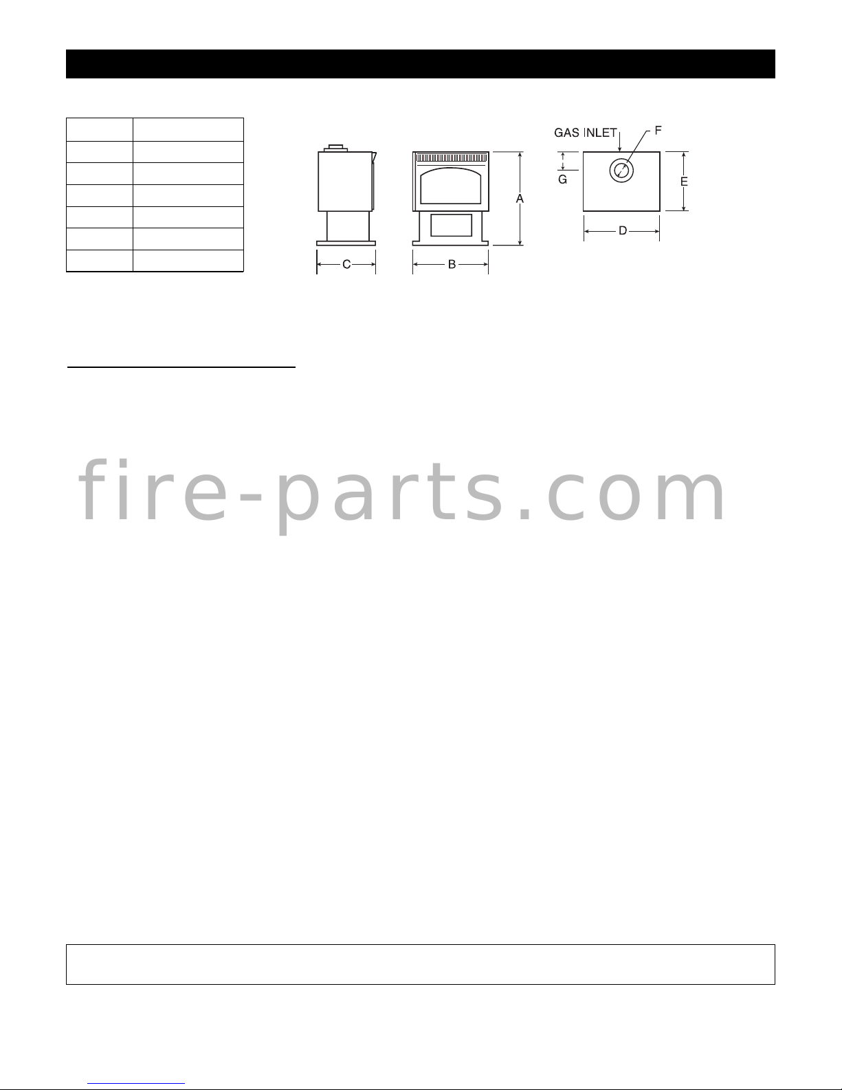
Gas inlet is located on the back of the unit.
INST
ALLATION REGULATIONS
This gas appliance must be installed by a qualified installer in accordance with local building codes, or in the absence
of local codes, with the current CAN\CGA-B149.1 or .2 Installation Code (in Canada) or the current National Fuel
Gas Code Z223.1 when installed in the United States.
This appliance, when installed, must be electrically connected and grounded in accordance with local codes, with the
current CSA C22.2 Canadian Electrical Code or with the national Electrical Code; ANSI/NFPA 70-1987 when
installed in the United States.
This unit is certified for installation in a bedroom or bed sitting room, the unit must be installed with listed thermostat.
Efficiency rating of the appliance is a product thermal efficiency rating determined under continuous operating and
was determined independently of any installed system.
FOR SAFE INSTALLATION AND OPERATION OF YOUR GAS STOVE PLEASE NOTE THE
FOLLOWING:
1. This appliance gives off high temperatures and should be located out of heavy traffic areas and away from
furniture and draperies.
2. Children and adults should be alerted to the hazards of the high surface temperatures of this appliance and
should stay away to avoid burns or ignition of clothing.
3. Children should be carefully supervised when they are in the same room as your fireplace appliance.
4. Under no circumstances should this appliance be modified. Any parts that nave to be removed for servicing
should be replaced prior to operating this appliance.
5. Installation and any repairs should be done by a qualified service person. A professional service person
should be called to inspect this appliance annually. Make it a practise to have all gas appliances checked
annually.
6. Control compartments, burners and air passages in this appliance should be kept clean and free of dust and
lint. Make sure that the gas valve and pilot are turned off before you attempt to clean this unit.
4
A 27 3/4”
B 22 3/4”
C 17”
D 23 1/4”
E 19”
F4”
G 6 1/4”
NOTE: It is recommended that a Carbon Monoxide (CO) Detector be installed in or near bedrooms and on all
levels of your home. Place a detector about 15 feet (4.5 meters) outside the room that houses your gas appliance.
f i r e - p a r t s . c o m
Page 5
LOCATING YOUR APPLIANCE
The unit should be placed on a hard, stable surface. The appliance may be installed directly on carpeting, tile or other
combustible material with no additional floor protection being required.
5
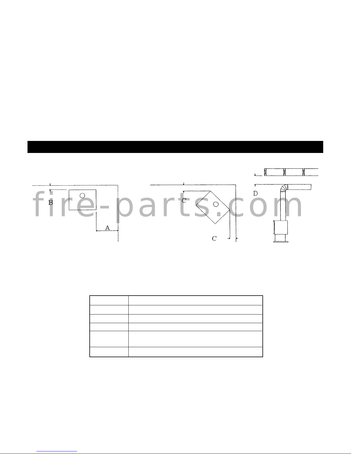
THE FOLLOWING MINIMUM DISTANCES TO COMBUSTIBLES MUST BE
OBSERVED TO ENSURE SAFE OPERATION OF YOUR STOVE.
7. The venting system (chimney) of this appliance should be inspected at least once a year and if needed, your
venting system should be cleaned.
8. Keep the area around your appliance clear of combustible materials, gasoline and other flammable vapours and
liquids. This appliance should not be used as a drying rack for clothing nor should Christmas stockings or
decorations be hung from it.
9. Under no circumstances should any solid fuels ( wood, paper) be used in this appliance.
10. For safe operation, purge gas line with glass door removed to assure a continuous flow of gas to the burner. Glass
doors must be installed for stove to operated safely.
11. Do not use this heater if any part has been under water. Immediately call a qualified service technician to inspect
the heater and to replace any part of the control system and any gas control which has been under water.
12. Do not operate appliance unless completely installed as per installation instructions.
Minimum distance to combustibles
A 6” from side of unit
B 4” from back of unit
C 3” from side of unit in corner (45°) installation
D 4” from top of 90° elbow or check with
Manufacturer’s Venting Clearances
E Check with Manufacturer’s Venting Clearances
f i r e - p a r t s . c o m
Page 6
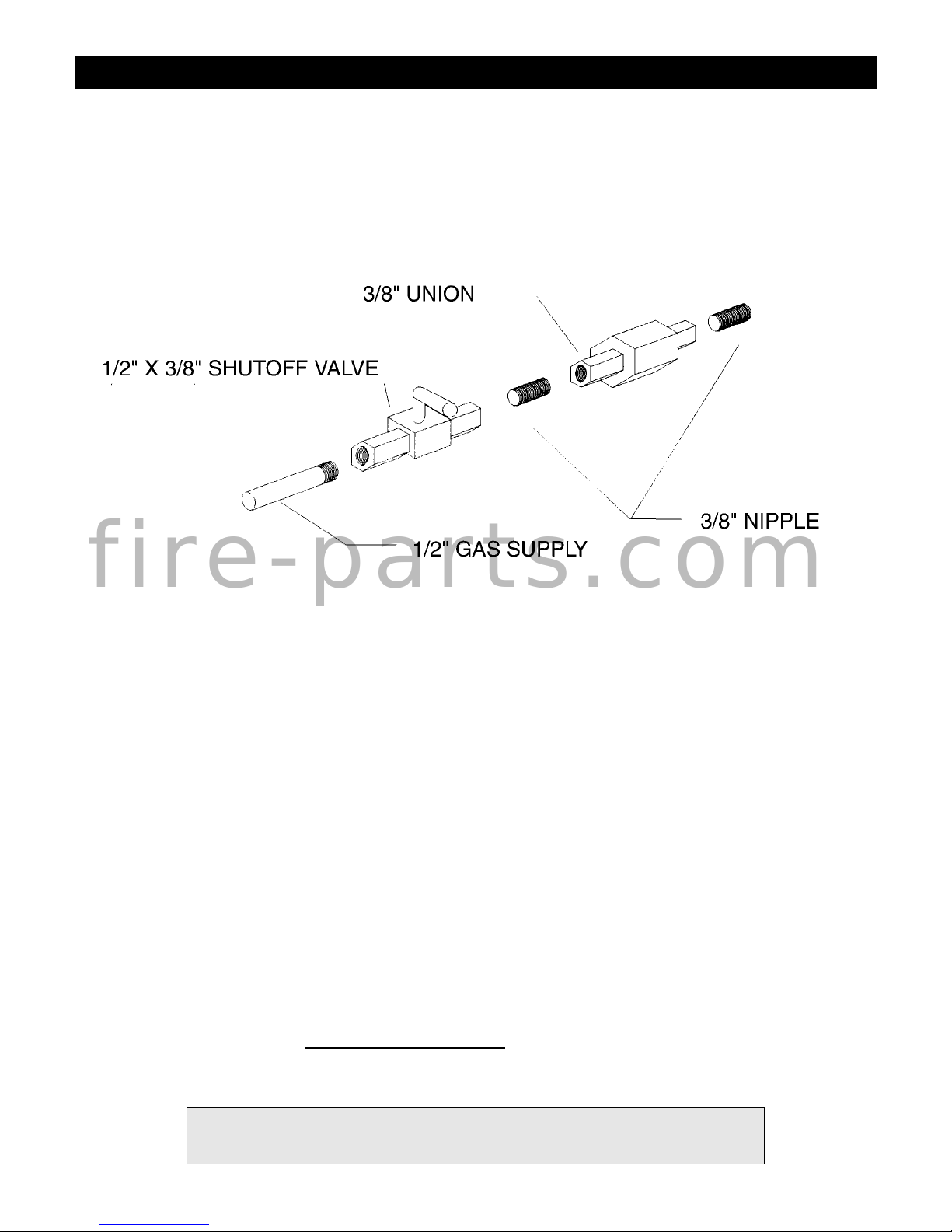
GAS LINE INSTALLATION
1. The gas pipeline is brought into the unit on the back left side of the unit.
2. The gas control inlet is 3/8". Typical installation layout for rigid pipe is shown below.
3. When using copper or flex connector, use only approved fittings. Always provide a union so that gas line
can be easily disconnected for burner or fan servicing. See gas specification for pressure details and ratings.
4. When a vertical section of gas pipe is required for installation, a condensation trap is needed.
See CAN/CGA-B149.1 or .2 for code details.
5. For natural gas, a minimum of 3/8" iron pipe with gas minimum pressure of 4.5" w.c. must be used for supply
from the gas meter. Consult with the local gas utility if any questions arise concerning pipe sizes.
6. 1/8" NPT plugged tappings are accessible for test gauge connection both on the inlet and outlet of the gas
valve.
7. Turn the gas supply ON and check for leaks. DO NOT USE OPEN FLAME FOR THIS PURPOSE. Use an
approved leak testing solution.
8. The appliance and its individual shutoff valve must be disconnected from the gas supply piping system during
any pressure testing of that system at test pressures in excess of 1/2 PSIG (3.5 KPa).
9. The appliance must be isolated from the gas supply piping system by closing its individual shutoff valve
during any pressure testing of the gas supply piping system at test pressures equal to or less than 1/2 PSIG
(3.5 KPa).
NOTE: The gas line connection may be made of 1/2" rigid pipe or an approved flex connector. Since some
municipalities have additional local codes, it is always best to consult your local authorities and the current
CAN/CGA-B149.1 or .2 installation code in Canada or the National Fuel Gas code ANSI Z223.1 in the U.S.A.
For the state of Massachusetts a T
-handle gas shut-off valve must be used on a gas appliance. This T-handle gas
shut-off valve must be listed and approved by the state of Massachusetts. This is in reference to the state of
Massachusetts state code CMR238.
This gas appliance should be installed by a qualified installer in accordance with local building codes and with current
CAN\CGA-B149.1 or .2 installation codes for Gas Burning Appliances and Equipment in Canada and the National
Fuel Gas Code Z223.1 in the United States.
NOTE: IF THE OPTIONAL FAN KIT IS TO BE INSTALLED IT IS HIGHLY RECOMMENDED THAT IT
BE ATTACHED TO THE STOVE BEFORE THE STOVE IS PUT IN ITS FINAL POSITION.
6
IMPORTANT: Always check for gas leaks with a soap and water solution.
Do not use open flame for leak testing.
f i r e - p a r t s . c o m
Page 7

GAS SPECIFICATIONS
OPERATING AND MAINTENANCE INSTRUCTIONS
This gas appliance should be installed by a qualified installer in accordance with local building codes and with
current CAN/CGA-B149.1 or .2 installation codes for Gas Burning Appliances and Equipment.
FOR SAFE INSTALLATION AND OPERATION NOTE THE FOLLOWING:
This appliance gives off high temperatures and should be located out of heavy traffic areas and away from furniture
and draperies.
Children and adults should be alerted to the hazards of high surface temperatures of this appliance and should stay
away to avoid burns or ignition of clothing.
Control compartments, burners and air passages in this appliance should be kept clean and free of dust and lint. Make
sure that the gas valve and pilot light are turned off before you attempt to clean this unit.
7
WARNING: WHEN PURGING THE GAS LINE, THE GLASS
FRONT MUST BE REMOVED.
FUEL GAS MAXIMUM INPUT
MAXIMUM OUTPUT
CONTROL (BTU) (BTU)
HIGH LOW HIGH
NATURAL GAS MILLIVOLT 32,000 25,000 23,700
PROPANE GAS MILLIVOLT 32,000 22,500 24,320
GAS INLET SIZE 1/2”(WR)
GAS INLET SIZE 3/8”(SIT)
MAXIMUN EFFICIENCY (FAN ON)
(78 NG), (80% LP)
NATURAL GAS 4.5 7 9
PROPANE GAS 10.8 11 12
GAS SUPPLY MINIMUM NORMAL MAXIMUM
PRESSURE
(INCHES WATER COLUMN)
UNIT TYPE MANIFOLD PRESSURE
(INCHES WATER COLUMN)
NATURAL GAS 3.5
PROPANE GAS 10.5
UNIT TYPE Orifice Size /
Air
Shutter Setting
NATURAL GAS (0-4500 FT) (35) Air Shutter.102”
PROPANE GAS (0-4500 FT) (51) Air Shutter .437”
f i r e - p a r t s . c o m
Page 8

GENERAL GLASS INFORMATION
8
The venting system (chimney) of this appliance should be inspected at least once a year and if needed, your venting
system should be cleaned.
Keep the area around your appliance clear of combustible materials, gasoline and other flammable vapours and
liquids.
Under no circumstances should this appliance be modified. Parts that have to be removed for servicing should be
replaced prior to operating this appliance again.
Installation and any repairs to this appliance should be done by a qualified service person. A professional service
person should be called to inspect this appliance annually. Make it a practice to have all of your gas appliances
checked annually.
Never use your gas stove as a cooking device.
The Burner/Log Assembly has been engineered and permanently adjusted for proper flame control.
Periodically remove the logs from the grate assembly and vacuum any loose particles from the grate and burner areas.
This appliance should not be used as drying rack for clothing, nor should Christmas stockings or decorations be hung
near it.
Under no circumstances should any solid fuels (wood, paper, cardboard, coal) be used in this appliance.
NOTE: it is normal for your gas stove to give off some odour the first time it is burned. This is due to the curing
of the paint and any undetected oil from the manufacturing process.
Please ensure that your room is well ventilated - open all windows.
It is recommended that you burn your gas stove for at least four (4) hours the first time you use it without the fan on.
GLASS CLEANING
It will be necessary to clean the glass periodically. During start-up, condensation, which is normal, forms on the inside
of the glass and causes dust, lint etc. to cling to the glass surface. Also, initial paint curing can deposit a slight film
on the glass. It is therefore recommended that initially the glass be cleaned two or three times with non-abrasive
common household cleansers and warm water. After that, the glass should be cleaned two or three times a season
depending on the circumstances.
DO NOT ALTER GAS ORIFICE.
f i r e - p a r t s . c o m
Page 9

9
CAUTIONS AND WARNINGS
DO NOT CLEAN WHEN THE GLASS IS HOT.
THE USE OF SUBSTITUTE GLASS WILL VOID ALL PRODUCT WARRANTIES.
CARE MUST BE TAKEN TO AVOID BREAKAGE OF THE GLASS.
DO NOT OPERATE THIS STOVE WITHOUT THE GLASS DOORS OR WITH A BROKEN GLASS DOOR.
DO NOT STRIKE OR ABUSE GLASS.
GLASS REPLACEMENT
Only Robax ceramic or coated Neoceram glass may be used for replacement. It must be a minimum of 5mm thick.
REMOVAL
OF THE GLASS DOORS
1. Remove top front grill by gently lifting the grill up and pulling towards you.
2. Remove the two screws on top of the door. Then lift the door out of door rest.
3. To replace glass, clean all material from door frame.Using a high temperature sealant (temperature-resistant to
500°F (260°C)) apply a bead of approximately 1/8" to all four sides of frame and insert glass with new gasket. Frame
should be placed on a flat surface with a small amount of weight pressing glass into sealant. Let dry approximately
15 to 20 minutes. The door can be reinstalled by reversing Steps 1,2.
LOG ASSEMBLY
1. Remove front door as described above.
2. Remove logs from carton (4) and inspect.
3. Centre rear log on rear log holder attached to back of firebox above and to the rear of the pilot birner.
4. Centre front log on front burner and push it back against stops. When correctly installed the log should not cover any of
the holes in the front burner.
5. Place top logs across the front and rear logs in the slots provided.
6. Purge gas lines and test pilot operation WHILE DOOR IS STILL
OFF.
7. Tear ember wool into small, thin, irregular pieces and place evenly over the front burner.
8. Replace glass door. The door must be installed before operating the fireplace.
f i r e - p a r t s . c o m
Page 10

LOGC5 OR LOGF5 PLACEMENT GUIDELINES
Step (1) Remove logs from carton and inspect each log.
Step (2) Break glowing embers into thumbnail size. Place glowing embers evenly
on to the front burner. Do not go over the grate.
Step (3) Place front log over front burner with the left & right sides against
the front grate.
Step (4) Place rear log on to the log retainer.
10
f i r e - p a r t s . c o m
Page 11

Step (5) Place right crossover log into the slots that are provided. Bark should be to the
outside.
Step (6) Place left crossover log into the slots that are provided. Bark should
be to the outside.
Step (7) Purge lines and test pilot operation.
Step (8) Replace glass door.
LOGC5 OR LOGF5 PLACEMENT GUIDELINES (continued)
11
f i r e - p a r t s . c o m
Page 12

12
FV/FDV 5000 OPTIONAL FAN KIT INSTALLATION
Caution: Do not connect any wires from the fan assembly to the Gas Valve.
NOTE: FOR EASE OF INSTALLATION THE FAN KIT SHOULD BE INSTALLED BEFORE THE STOVE IS
PUT IN ITS FINAL POSITION.
AUT
OMATIC ON/OFF THERMOSTAT CONTROLLED FAN KIT (Part #F35FK)
1. Open Access Door where the piezo-igniter is located and install the variable speed control in the hole provided opposite the
piezo-igniter.
2. Locate the two fan mounting bracket screws in the rear of the unit as shown in the above diagram Fig.1, remove one of the screws
and loosen the other screw. Place the fan mounting bracket in position and tighten screws.
3. Locate the two fan mounting screws as shown in the diagram and place the key holes on the fan over the mounting screws and drop
into position.
4. Connect the wires to the sensor and variable speed control as shown in the diagram. Connect the fan extension cord to 110volt power.
5. Turn the variable speed control to the on position (clockwise). NOTE: The stove must now be installed and gas line attached before
proceeding.
6. Turn the stove on. Once the sensor unit reaches operating temperature (in approximately 10 to 15 minutes) the fan will turn on. The
fan can be switched off, if desired by turning the switch fully counter-clockwise.
7. Once the fan has started to turn it may be desirable to adjust the minimum fan speed. Tilt the control panel forward to access the
rear of the variable speed switch, turn the variable speed switch to its minimum setting (fully clockwise). Use the set screw on the
side of the variable speed control to increase or decrease the minimum fan speed. (It may be desirable to lower minimum fan speed
to decrease the sound level created by the fan.) Reinstall the control panel.
f i r e - p a r t s . c o m
Page 13

13
MILLIVOLT SYSTEM, LIGHTING, & BURNING CONTROL
TO TURN OFF GAS APPLIANCE
Turn off all electric power to the appliance if service is to
be performed. Open control access door. Push in gas
control knob slightly and turn clockwise to "OFF". Do not
force. Close control access door.
Pilot Burner
Adjustment
l. Remove pilot adjustment cap.
2. Adjust pilot screw to provide proper sized flame
3. Replace pilot adjustment cap.
4. Leak test.
NOTE: The "On/Off" switch may be replaced with a wall
thermostat which allows the main burner to light and turn
off automatically depending upon the thermostat setting
and room temperature.
LIGHTING INSTRUCTIONS
1. Open access door on front of unit.
2. Push in gas control knob slightly and turn clockwise
to "OFF". NOTE: Knob cannot be turned from
"PILOT" to "OFF" unless knob is pushed in slightly.
Do not force.
3. Wait five (5) minutes to clear out any gas remaining
in burner combustion chamber.
4. Turn knob on gas control counter-clockwise to
"PILOT".
5. Push in control knob all the way and hold in.
Immediately light the pilot with piezo-electric ignitor
while continuing to push knob in for one (1) minute.
Release knob. Pilot should remain lit. If it goes out,
repeat steps 2 through 5 until pilot remains lit. - If
knob does not pop up when released, stop and
immediately call your service technician or gas
supplier. - If pilot will not stay lit after several tries,
turn the gas control knob to "OFF" and call your
service technician or gas supplier.
6. Turn gas control knob counter-clockwise to "ON".
7. All models are supplied with a switch that turns the
main burner on or off. This switch which is located
next to the piezo-electric igniter must be turned to on
in order for the main burner to light. (Be sure switch
is connected to valve.)
8. Adjust the gas flow (flame height) with the HI/LO
gas control knob on valve to the desired level.
SPILL SAFETY SWITCH - Wiring Diagram
820-639 and 820-640 True Millivolt Systems
This System does not have a thermocouple
For serial numbers greater than 4740.
F
M
F
M
CONNECT ONE BLUE LEAD
TO MALE LEAD OF
SPILL SWITCH, AND THE
OTHER BLUE LEAD MALE
TO FEMALE LEAD OF
SPILL SWITCH
TO THERMOCOUPLE
CONNECT TO THERMOCOUPLE AT
VALVE REAR LOCATION
S.I.T. VALVE
TOP VIEW
VENT SAFETY SPILL
SWITCH LOCATED IN
REAR OF UNIT
UNDER DRAFTHOOD
THERMOCOUPLE OPTIONAL
FRONT LOCATION
For SIT 820633-820634 Valves
Use on 820633
and 820634
f i r e - p a r t s . c o m
Page 14

14
VENT INSTALLATION
VENTING INSTRUCTIONS
NOTE: A chimney venting this stove shall not vent
any other appliance.
This appliance may be vented in various types of
applications, 'A' Vent of solid fuel wood burning
chimney. Masonry Clay lining and 'B' Vent liquid
fuel gas chimney. A 90 degree elbow can be installed
directly off the “B” vent Convertor. (See Above
Diagram)
NOTE: Four (4) inch is required if existing
chimney is six (6) inches or larger. Four (4) inch
single wall or 'B' Vent liquid fuel gas chimney or
Flex Gas Liner may be used to adapt existing
chimney or liner to stove.
When installing with 'B' Vent liquid fuel gas chimney
install as per 'B' Vent Manufacturer installation
specifications. Horizontal and vertical, offset vertical
or vertical installations maybe installed.
NOTE: Installation of 'B' Vent must follow 'B'
Vent Manufacturers installation instructions when
being used.
Seal all connections in venting system.
Follow the 'B' Vent chart for horizontal vertical
venting or offset vertical venting. Minimum venting
12 ft. maximum 60 ft.
f i r e - p a r t s . c o m
Page 15

PARTS LIST
Par
t No. Description
LOG SET: required for eack unit
LOGF5 Log Set - Four Piece Fibre Split Oak (F5000, ZDV6000, VFI30,VFI25)
LOGC5 Log Set - Four Piece Cast Split Oak (F5000, ZDV6000, VFI30, VFI25)
ACCESSORY LIST
F35FK Fan Kit w/Variable Speed Control (Temperature Sensing)
F5GG Grill - Gold
F5ADDX Arch Door Frame - Deluxe Black (352)
F5ADG Arch Door Frame - Gold
Z1MT Thermostat Millivolt Wall Mount
Z80PT Thermostat Programmable Digital Millivolt Wall Mount (1F80-40)
ZIRC Remote Control Millivolt (On/Off with LED) (Model I)
ZART Remote Control Thermostat Millivolt (Model K)
RMCBN Remote Control - Basic - Natural Gas (On/Off, Hi/Lo Flame Adjustment)
RMCBP Remote Control - Basic - Liquid Propane (On/Off, Hi/Lo Flame Adjustment)
DCHS Remote Control Heatshield
REPLACEMENT
PARTS FOR FV5000
5000 - 190 Glass - Robax (13.25” x 20”)
1000 - 306 Thermalcord For Glass
5000 - 106 Top Grill
1000 - EMBERS Glowing Embers and Slag Kit
1000 - 214 Piezo-Igniter
1000 - 216 Stove On/Off Switch
1000 - 255-35 #35 Burner Orifice NG (0 - 4500 FT)
1000 - 255-51 #51 Burner Orifice LP (0 -4500 FT)
2000 - 080 Thermostat Fan Sensor
2000 - 085 Variable Speed Switch (Fan)
3000 - 930 Thermo Disc (Spill Switch)
CONVERSION KITS (For SIT Valve only)
5000V - CKLP LP Conversion Kit
5000V - CKNG NG Conversion Kit
BURNER
ASSEMBLY
AND VALVE SYSTEM PARTS
If Serial Number is LESS than 2049:
5000 - VBNGWR NG WHITE ROGERS BURNER ASSEMBLY C/W VALVE
1000 - P133WR Valve NG Hi/Lo (36D33U-100)
1000 - P134WR Pilot Burner (E39A1)
1000 - P135WR Thermocouple (H19E924)
1000 - P136WR Generator (G01A-524)
1000 - 206 Pilot Orifice (F069-2060)
5000 - VBLPWR LP WHITE ROGERS BURNER ASSEMBLY C/W VALVE
1000 - P101WR Valve LP Hi/Lo (36D33U-100)
1000 - P134WR Pilot Burner (E39A1)
1000 - P135WR Thermocouple (H19E924)
1000 - P136WR Generator (G01A-524)
1000 - 207P Pilot Orifice (F069-2067)
If Serial Number is BETWEEN 2050-4467 SYSTEM #1 OLD SIT SYSTEM:
5000 - VBLPSI LP SIT BURNER ASSEMBLY C/W VALVE
5000 - VBNGSI NG SIT BURNER ASSEMBLY C/W VALVE
1000-P136WR Thermopile GOAI-524
1001-P035SI Electrode Sparker 915.035 SIT
1001-P129SI Thermocouple 290.129 SIT unified
1001-P157SI Orifice Pilot LP 977.157 SIT
1001-P159SI Orifice Pilot NG 977.159 SIT
1001-P508SI HT Cable 16
1001-P633SI Valve Nova LP Hi/Lo 0820633
1001-P634SI Valve Nova NG Hi/Lo 0820634
1001-P605SI Pilot Burner LP 190.605 unified SIT
1001-P606SI Pilot Burner NG 190.606 unified SIT
15
f i r e - p a r t s . c o m
Page 16

If Serial Number is BETWEEN 4468-4740
SYSTEM #2 New Top Convertible SIT system:
5000 - VBLPSI LP SIT BURNER ASSEMBLY C/W VALVE
5000 - VBNGSI NG SIT BURNER ASSEMBLY C/W VALVE
1000-P136WR Thermopile GOAI-524
1001-P069SI Electrode Sparker 915.069 TC SIT
1001-P216SI Thermocouple 290.216 TC SIT
1001-P165SI Orifice Pilot NG 977.165 TC SIT
1001-P167SI Orifice Pilot LP 977.167 TC SIT
1001-P508SI HT Cable 16
1001-P633SI Valve Nova LP Hi/Lo 0820633
1001-P634SI Valve Nova NG Hi/Lo 0820634
1001-P713SI Pilot Burner LP 199.713 TC SIT
1001-P714SI Pilot Burner NG 199.714 TC SIT
If Serial Number
is GRETAER than 4740 only
SYSTEM #3 New SIT TC True Millivolt Vented :
5000 - VBLPSI LP SIT BURNER ASSEMBLY C/W VALVE
5000 - VBNGSI NG SIT BURNER ASSEMBLY C/W VALVE
1000-P136WR Thermopile GOAI-524
1001-P069SI Electrode Sparker 915.069 TC SIT
1001-P165SI Orifice Pilot NG 977.165 TC SIT
1001-P167SI Orifice Pilot LP 977.167 TC SIT
1001-P639SI Valve Nova LP Hi/Lo 0820639 True MV
1001-P640SI Valve Nova NG Hi/Lo 0820640 True MV
1001-P745SI Pilot Burner LP 199.745 TC TM
1001-P746SI Pilot Burner NG 199.746 TC TM
16
f i r e - p a r t s . c o m
Page 17

17
Trouble Shooting The Gas Control System
WARNING: BEFORE DOING ANY GAS CONTROL SERVICE WORK, REMOVE THE GLASS FRONT.
NOTE: Before troubleshooting the gas control system, be sure external gas shut off is in the “On” position.
Problem Possible Causes Corrective Action
Spark igniter will not light. Defective or misaligned electrode Check for spark at electrode and pilot: if no spark and electrode wire is
at pilot. properly connected, replace igniter.
Defective igniter Using a match, light pilot. If pilot lights, turn off pilot and push the red
(push-button) button again. If pilot will not light - check gap at electrode and pilot
should be 1/8” to 1/4” to have a strong spark.
Pilot will not stay lit after carefully Defective pilot generator, remote Check pilot flame. Must impinge on generator and thermocouple.
following lighting instructions. wall switch, or thermocouple Clean and/or adjust pilot for maximum flame impingement on
(flame switch where applicable) generator and thermocouple.
Be sure wire connections from generator at gas valve terminators
are tight and generator is fully inserted into pilot bracket.
One of the wall switch wires may be gerounded. Remove wall
switch wired from valve terminals if pilot now stays lit, trace
wall switch wiring for ground. May be grounded to appliance or
gas supply.
Check generator with millivolt meter. Take reading at generator
terminals of gas valve. Should read 325 millivolts minimum while
holding valve knob depressed in pilot position and wall switch
“off”.Replace faulty generator if reading is below specified minimum.
Defective valve magnet. Turn valve knob to “”On”, place wall switch to “On”. Millivolt meter
should read greater than 100mV. If the readingis okay and the burner
does not come on, replace the gas valve.
Pilot burning, no gas to burner, Wall switch or wires Check wall switch and wires for proper connections. Jumper wire
Valve knob “ON”, Wall defective. across terminals at wall switch. If burner comes on, replace defective
Switch “ON” wall switch. If okay, jumper wires, across wall switch wires at valve.
If burner comes on, wires are faulty or connections are bad.
Generator may not be generating Re-check symptom #2
sufficient voltage.
Plugged burner orifice. Check burner orifice for stoppage and remove.
Defective automatic valve Remove ON/OFF switch wires from gas valve. Install jumper wires
operator. from top bottom terminals of gas valve. Turn valve on “ON”. If main
burner does not light, replace valve.
Frequent Pilot outage problem. Pilot flame may be too low or Clean and/or adjust pilot flame for maximum flame impingement
blowing (high) causing the pilot on generator and thermocouple.
safety to drop out.
f i r e - p a r t s . c o m
Page 18

BASIC ONE YEAR WARRANTY
During the first year after installation, we will provide a replacement for any component part of your unit found to be defective in materials
or workmanship, including labour costs. Repair work requires prior approval by Kingsman, labour costs are based on a predetermined rate
schedule and any repair work must be done through an authorized Kingsman dealer.
LIMITED LIFETIME WARRANTY
The heat exchanger, combustion chamber and burner of every Kingsman product excluding the Outdoor Firepit are warranted against
materials or workmanship during the period the product is owned by the original owner. The part to be replaced must be returned to our
distributor in exchange for the replacement part. Any labor, material, freight and/or handling charges associated with any repair
or replacement pursuant to this Limited Lifetime Warranty will not be covered by this warranty.
GENERAL TERMS
In lieu of providing a replacement part, we may, at our option, provide the distributor's component purchase price from us or a credit equal
to the distributors component purchase price from us toward the purchase of any new unit which we distribute. If a credit is given
in lieu of a replacement part, the rating plate from the unit being replaced must be submitted on a warranty claim, and the unit being
replaced must be made available to our distributor for disposition.
In establishing the date of installation for any purpose, including determination of the starting date for the term of this Limited Lifetime Warranty,
reasonable proof of the original installation date must be presented*, otherwise the effective date will be based upon the date of manufacture
plus thirty (30) days.
We will not be responsible for and you, the user, will pay for: (a) damages caused by accident, abuse, negligence, misuse, riot, fire, flood,
or Acts of God (b) damages caused by operating the unit where there is a corrosive atmosphere containing chlorine, fluorine, or any other
damaging chemicals (other than in a normal residential environment) (c) damages caused by any unauthorized alteration or repair
of the unit affecting its stability or performance (d) damages caused by improper matching or application of the unit or the unit's components
(e) damages caused by failing to provide proper maintenance and service to the unit (f) any expenses incurred for erecting, disconnecting
or dismantling the unit (g) parts or supplies used in connection with service or maintenance (h) damage repairs, inoperation or inefficiency
resulting from faulty installation or application (i) electricity or fuel costs or any increase in electricity or fuel cost whatsoever including
additional or unusual use of supplemental electric heat.
We shall not be liable for any incidental, consequential, or special damages or expenses in connection with any use or failure of this unit.
We have not made and do not make any representation or warranty of fitness for a particular use or purpose, and there is no implied condition
of fitness for a particular use or purpose. We make no express warranties except as stated in this Limited Lifetime Warranty. No one is authorized
to change this Limited Lifetime Warranty or to create for us any other obligation or liability in connections with this unit. Any implied
warranties shall last for one year after the original installation. Some states and provinces do not allow the exclusion or limitation of incidental
or consequential damages or do not allow limitations on how long an implied warranty or condition lasts, so the above limitations or exclusions
may not apply to you. The provisions of this limited warranty are in additions to and not a modification of or subtraction from any statutory
warranties and other rights and remedies provided by law.
Save this certificate. It gives you specific legal rights, and you may also have other rights which may vary from state to state and province to province.
In the event your unit needs servicing, contact your dealer or contractor who installed or serviced your unit. When requesting service,
please have the model and serial number from each unit readily available. If your dealer needs assistance, the distributor is available for support
and we, in turn support the distributor's efforts.
Fill in the installation date and model and serial numbers of the unit in the space provided below and retain this limited warranty for your files.
Model No. Serial No. Date installed
Dealer or Contractor Name :
*
To receive advantage of your warranty, you must retain the original records that can establish the installation date of your unit.
LIMITED LIFETIME WARRANTY
This Limited Lifetime Warranty applies only while the unit remains at the site of the original
installation and only if the unit is installed inside the continental United States, Alaska, Hawaii,
and Canada. The warranty applies only if the unit is installed and operated in accordance
with the printed instructions and in compliance with applicable installation and building codes
and good trade practices.
The Ultimate in Design, Engineering & Quality
f i r e - p a r t s . c o m
 Loading...