

Kingsley KIP-20 Operation And Maintenance Manual
1
KIP-20
OPERATION AND MAINTENANCE MANUAL
WIRE MARKING MACHINE
5307 Meadowland Parkway Marion, Illinois 62959
Kingsley, ITW Marking and Coding
Phone (866) 421-9898 Fax (618) 997-1766
2
INTRODUCTIOIN
GENERAL
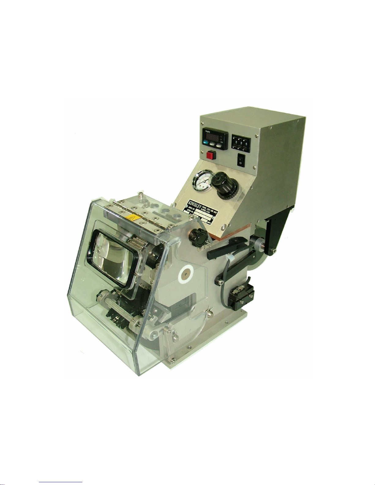
The KIP-20 as shown in Figure 1 is a remote-operation wire-marking machine. It is
designed to work as a SLAVE unit in an assembly process and mark on command from a
host signal. The machine provides permanent marking of alpha/numeric characters in
vertical and horizontal formats on insulated wire. It can be configured for continuous
incremental marking or simultaneous end marking.
The KIP-20 uses full-size-40-character typewheels to mark single or compound legends up
to 2.9 inches (7.4 cm.) in length. The machine can hold up to 28 typewheels. It is capable
of marking on insulated wires or cables from 0.038 inch (0.965 mm.) to 0.750 inch (19.05
mm.) outer diameter. It requires 115 VAC (230 VAC optional) electrical source and 100
psi. at 5 cfm. Compressed air source.
Figure 1 KIP-20 Wire Marking Machine
3
SPECIFICATIONS:
SCOPE OF MANUAL
Dimension W x H x D in inches (cm) …………………….. 7 X 14 X 15 (17.8 X 35.6 X 38.1)
Weight Net …………………………………………………………………………25 lb. (11.4 kg)
Electrical requirement 115 VAC 4 Amp. …………………………(230 VAC 3 Amp. optional)
Legend length in inches (cm.) …………………………………………………………..2.9 (7.4)
Type ………………………………………40 Character typewheels made of hardened steel
Speed ……………………………………………………………..Up to 350 imprint per minute
Dwell ………………………………………………………………..Adjustable (0.5 – 1 second)
Actuation ……………………………………………………………….Direct-acting air cylinder
Air supply requirement ………………………………………………………….100 psi at 5 cfm
Heater …………………………………………………..425 Watt, 15 VAC (230 VAC optional)
Marking foil ……………………………………100 foot (30.5 m) or 600 foot (183.0 m) length
Control …………On/OFF, Electronic dwell timer, Temperature controller, and Test mark
button
Indicators ……………………………...Power On, Temperature readout, Air pressure gauge
This manual provides instructions for the installation, operation, periodic maintenance, and
troubleshooting of the KIP-20 Wire Marking Machine. It is intended to be used by operators
and plant maintenance personnel.
A list of recommended spare parts in located at the back of the manual. In order to
minimize downtime, Kingsley recommends that the suggested quantity of each part to be
kept on hand for each marking machine in service.
A complete parts list and exploded view of the marking machine is included as a guide for
ordering parts.

4
INSTALLATION
UNPACKING AND INSPECTION
All components of the wire-marking machine were inspected and carefully packed prior to
shipping. After opening the boxes, carefully inspect all the components for damage that
may have occurred during shipment. Report any damage immediately to the carrier and to
Kingsley. Ensure that all the components on the shipping order were delivered.
You should have the following components:
1 KIP-20 Wire Marking Machine with heavy-duty power cord.
1 Air Filter/Regulator Assembly mounted on the back of the machine.
1 Male Connector for host inters connection.
Installed typewheels (if ordered)
If any components are missing, report the shortage immediately to Kingsley.
MOUNTING
Before mounting the KIP-20, ensure that the installation site is properly prepared. Proper
electrical supply must be within reach of the power cord. The compressed air supply must
reach the air regulator mounted on the back of the machine. The machine interconnects
attaches to the right side of the control box.
The machine base is designed to provide secure mounting to a process line or bench top.
Use the following procedure to mount the wire-marking machine.
1. Place the machine in position where it is to be mounted.
2. Use the base as a template and mark the four mounting holes.
3. Remove the machine and drill four holes.
4. Attach the machine to the mounting surface using appropriate ¼ inch
hardware. Ensure that the machine is securely mounted and will not move
during operation.
INTER CONNECTION OF WIRE MARKING AND HOST MACHINE
In order to synchronize the printing with the host machine, the host must initiate the print
pulse input command. A four wire female connector is provided to connect the host
machine to the wire-marking machine. Two wires from pins 1 and 2 must be connected to
the host machine, where contact closure is used to trigger a print pulse. Use the following
procedure to connect the controller to the host machine.
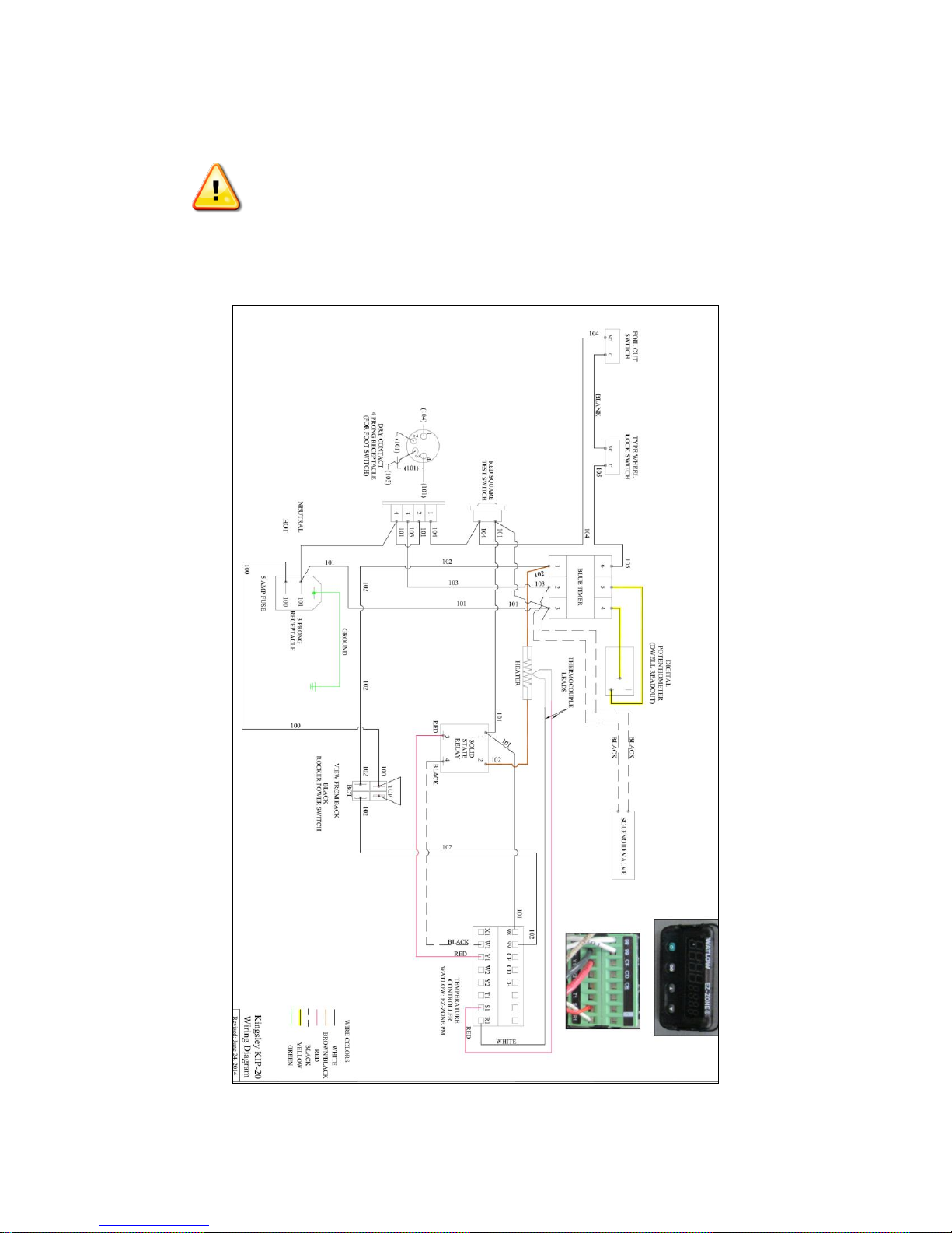
Figure 2 is the wiring diagram of the KIP-20. The 4-conductor connector provides the
means for the host machine to control the wire-marking machine.
5
An incorrectly wired interconnect cable can cause damage to the wire
marking machine. If you are not sure how to wire the interconnect cable,
call Kingsley before connecting the KIP-20.
Ensure that the mating male connector is properly wired and connected to the host
machine and insert the connector into the female mounted on the side of the control box
on the KIP-20.
Figure 2 Wiring Diagram

6
POWER CONNECTION
Never use an ungrounded electrical power source. Using an ungrounded
or improperly grounded source can result in a risk of electric shock and
serious injury or death.
The use of non-dedicate AC electrical service to the wire-marking
machine may result in improper operation and damage to the equipment.
The KIP-20 requires 4 Amp. 115 VAC (3 Amp 230 VAC optional) of available incoming
power. Ensure that the available power is sufficient for the system and that electrical
equipment and installation meets all national and local codes.
Ensure that the ON/OFF switch is in the OFF position, and plug the power cord into the
properly ground power source.
AIR CONNECTION
The use of non-filtered or unregulated compressed air supply may
result in improper operation and damage to the equipment. The KIP20 ships with a filter and regulator assembly that must be used.
Endure that the supply source is capable of maintaining a constant air
pressure of 100 psi.
The air cylinder and the control valve are pre-lubricated. The KIP-20 requires a filtered
unlubricated and regulated 100 psi. air source to ensure that the air supply meets the
requirements of the machine.
High-pressure compressed air used in the imprinter can cause
serious injury to eyes and other sensitive tissue. Always wear
safety glasses when working with compressed air. Being hit by
runaway hoses can result in serious injury. Never try to grab a
runaway hose. Immediately shut off air supply if a hose or fitting
breaks. Shield yourself from broken compressed air lines or
fittings.
Use the following procedure to connect the air supply to the wire-marking machine. Use
suitable sealant on the threads of all the fittings on the air lines.
1. Bring the ¼” airline to the input side of the filter/regulator.
2. Attach the air line and tighten the fittings.
3. Dress the airline to ensure that there are no kinks and that it is protected from any
moving parts.
4. Open the supply valve to apply air to the imprinter.
5. Check for air leaks and tighten fitting if necessary.
7
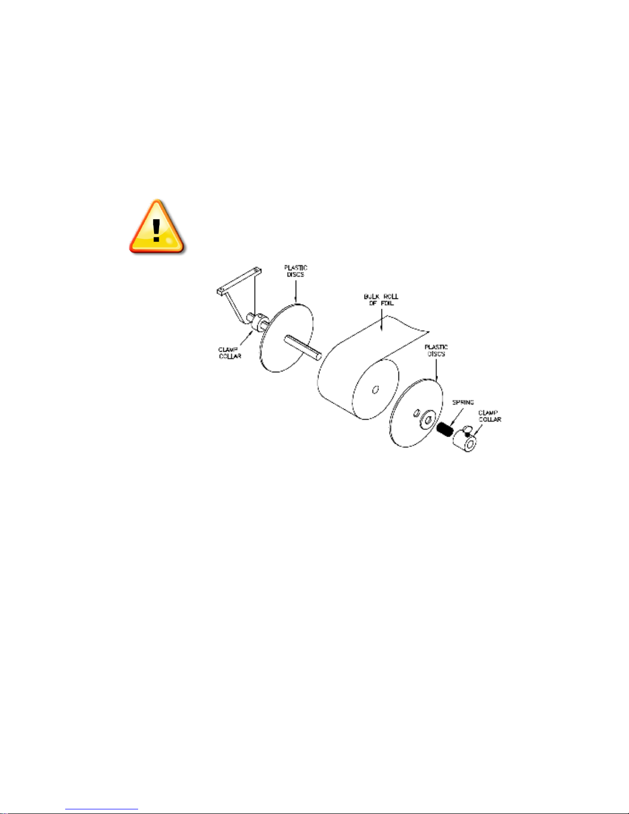
INSTALLING FOIL
Specific foils are used for different types of wire insulation. Ensure that you are installing
the foil selected for your particular application. Appendix A lists foils available from
Kingsley, their typical application, and approximate machine settings for that foil.
The roll of foil mounts on the foil spool shaft at the back of the machine. Use the following
procedure to install a roll of foil.
Temperature within the unit can approach 500 F (260 C). Contact
with high-temperature surfaces can cause serious burns. Avoid contact
with all hot components in the wire-marking machine.
Figure 3 Installing Roll of Foil
1. Ensure that the ON/OFF switch is in the OFF position and the machine is cool.
2. Refer to Figure 3 and remove and retain the clamp collar, spring, and washer from the foil
spool shaft by unscrewing the thumbscrew.
3. Remove and retain the plastic disc from the shaft.
4. Adjust the rear clamp collar to center the foil on the spool shaft.
Note: The shiny side of the foil must be facing up and unwind off the top of the roll.
5.
a. In the case of a 100’ roll of foil insert the bulk roll of foil on the spool shaft.
b. In the case of a 600’ roll of foil use one spacer to set as an internal core
spacer. The 600’ core size is larger in diameter than the foil dispenser
shaft.

8
6. Install plastic disc and secure the assembly with the washer, spring, and clamp collar.
The foil must thread under the “Foil Out” lever or the wire-marking machine will not
operate.
7. Feed a scrap piece of paper or thin object from the front of the machine toward the back
and under the ““Foil Out" lever just in front of the spool of foil.
8. Tape the end of the foil to the scrap of paper and pull the foil to the front of the machine.
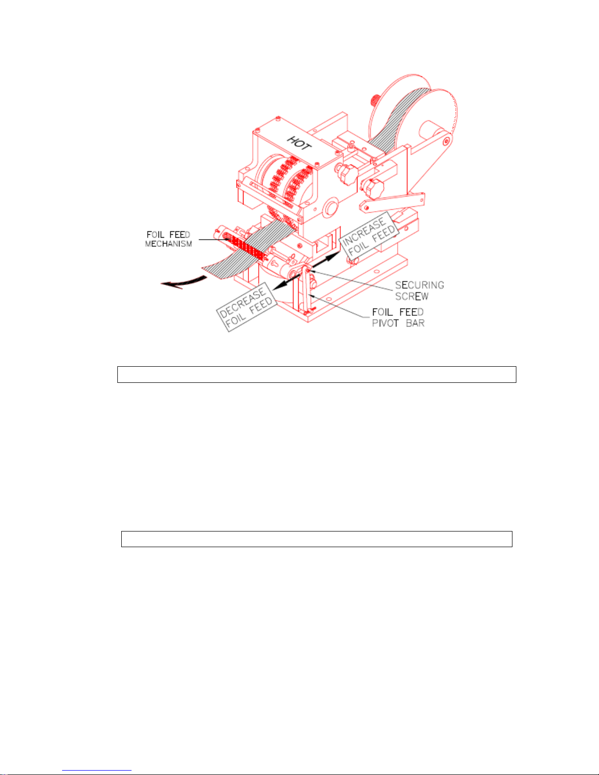
9. Refer to Figure 4 and thread the foil between the knurled rollers. Manually turn the knurled
rollers with feed knob to advance the foil through the knurled rollers. Ensure that the
foil is feeding straight and that it is centered to the typewheels.
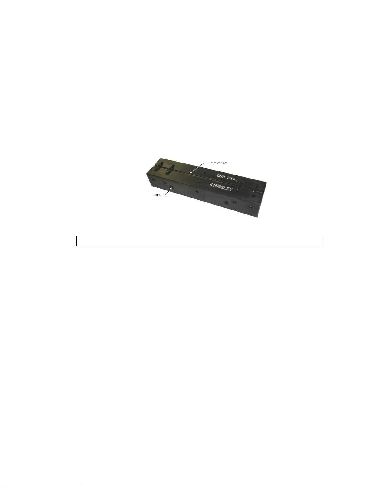
SELECT AND INSTALLING THE WIRE FIXTURE
Kingsley offers a complete range of wire holding fixture sizes (refer to Appendix B). Figure
5 illustrates the wire fixtures and calls out the important elements: Wire Guide and Wire
Groove.
Note: It is possible to inadvertently use a wire fixture that is too large for a
wire, for example using a 0.076 inch (19.3 mm) fixture for 0.072 inch (18.29
mm) outside diameter wire. The wire will not seat correctly and may move
laterally in the close tolerance groove during the marking process. Wire
marking will be inconsistent. The type may also cut or nick the insulation.
Figure 4 Loading Foil into Feed Mechanism
9
It is also possible to use a wire fixture that is too small for a wire since guides are oversize by
0.010 inch (0.254 mm). During the marking phrase, the type will drive the larger diameter wire
into the small radius wire groove. Depending on the insulation material, the wire may become
tightly wedged in the groove making it difficult for the host machine to advance the wire for the
next mark.
Use the following procedure to mount the wire fixture.
1. Orient the fixture so that the test hole and mounting dimples face the front
of the machine.
2. Insert the fixture from the left side of the machine and slide it into the
master fixture. Pus the fixture to the right until it hits the stop pin.
3. Secure the fixture by tightening the two locking setscrews until they are
snug.
Figure 5 Wire Fixture
SETTING THE LEGEND
If Typewheel were ordered with the KIP-20, they were mounted at the factory, and the unit is ready
to operate. If Typewheel were ordered separately, they must be installed before the KIP-20 is
ready to operate. Refer to INSTALLING TYPEWHEELS in the MAINTENANCE Section of this
manual to install or change typewheels.
Use the following procedure to set the typewheels for the correct legend.
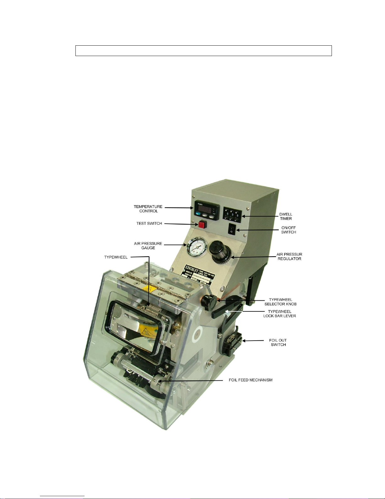
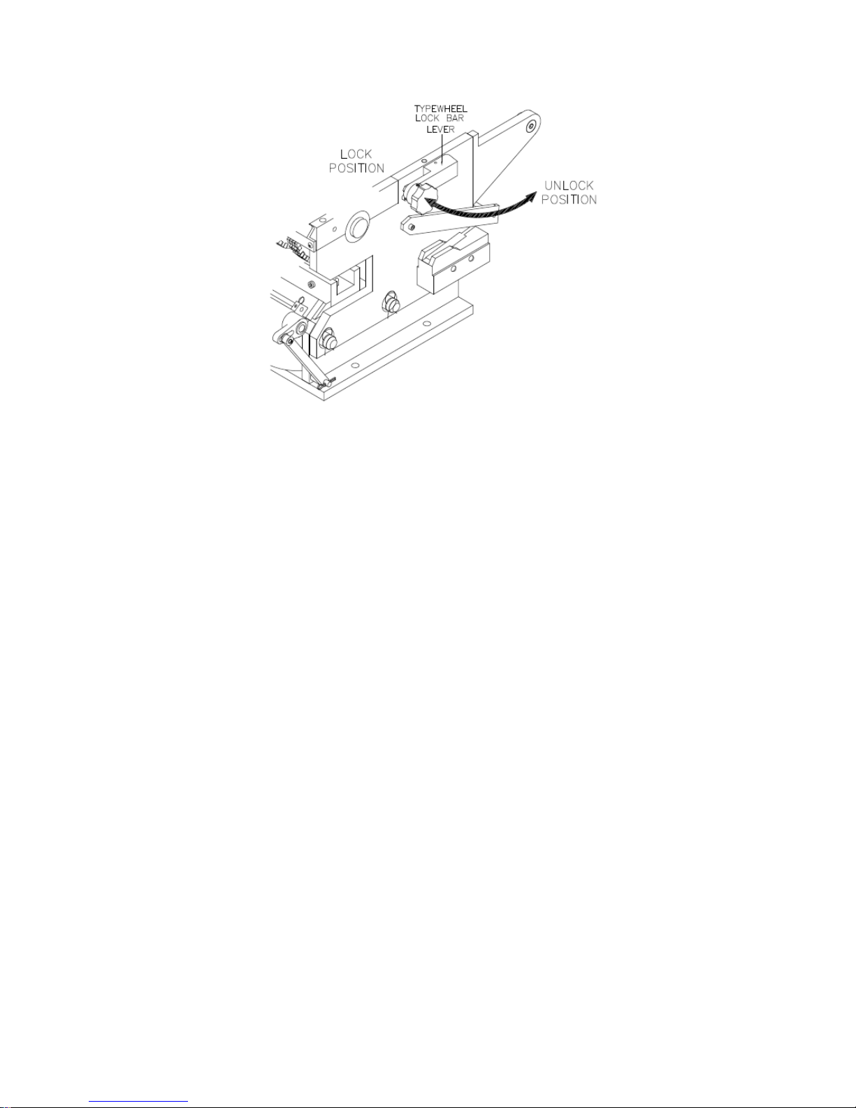
1. Refer to Figure 6 and disengage the typewheel lock bar by swinging the lever out. The lever
unlocks the typewheels and opens the type lock micro switch preventing the machine from
stamping.
NOTE: It may be necessary to rotate the knob on the selector slightly to allow the selector to
slide past the typewheels.
10
Figure 6 Typewheel Lock Bar
2. Refer to Figure 7, and slide the selector bar until the position indicator aligns with the
typewheel you wish to adjust.
3. Use the sight glass to view the markings on the typewheel. The character visible beneath the
imprint tooth indicates the character that will be marked on the wire.
4. Slowly rotate the control knob to rotate the typewheel. When the correct character is visible in
the sight glass, the typewheel is in the correct position.
5. Repeat steps 2 and 3 for each of the typewheels.
6. When all the typewheel are in the correct position, engage the typewheel lock bar by pivoting
the lever to the typewheels are in the correct position, engage the typewheel lock bar by
pivoting the lever to the closed position. The typewheels cannot be rotate when the typewheel
lock bar is engaged.
11
Figure 7 Setting the Typewheel
POWER UP
After all components are installed, the system is ready to start. Use the following
procedure to start the system and check the installation.
1. Ensure that the air supply is on.
2. Place the ON/OFF switch in ON position. The power indicator lights and
the temperature controller displays the current heater temperature.
3. The compressed air gauge indicates the air pressure setting of the
regulator.
4. If everything is operating normally, the initial settings can be
programmed.
INNITIAL SETTINGS
If the system powered up properly, the initial settings for temperature, air pressure, and
dwell can be programmed.
Temperature is the amount of heat required to bond the foil to the marking surface.
Different material requires different temperatures. Refer to Appendix A for the
approximate temperature setting for the foil being used.
Pressure is the amount of forces (pounds per square inch) that is applied to the foil and the
marking surface. The air pressure regulator adjusts the air pressure. If too much pressure
12
is applied, the insulation on the wire may be damaged. If too little pressure is applied, the
quality of the imprint will be unsatisfactory.
Dwell is the length of time the hot type is in contact with the foil and the marking surface.
The timer controls dwell.
The correct balance of all three elements is required for a quality imprint. Experiment with
particular insulation and foils will determine exact settings. If the settings are not known,
use the following as a starting point.
Temperature: 250 F
Air Pressure: 20 psi
Dwell: ½ second
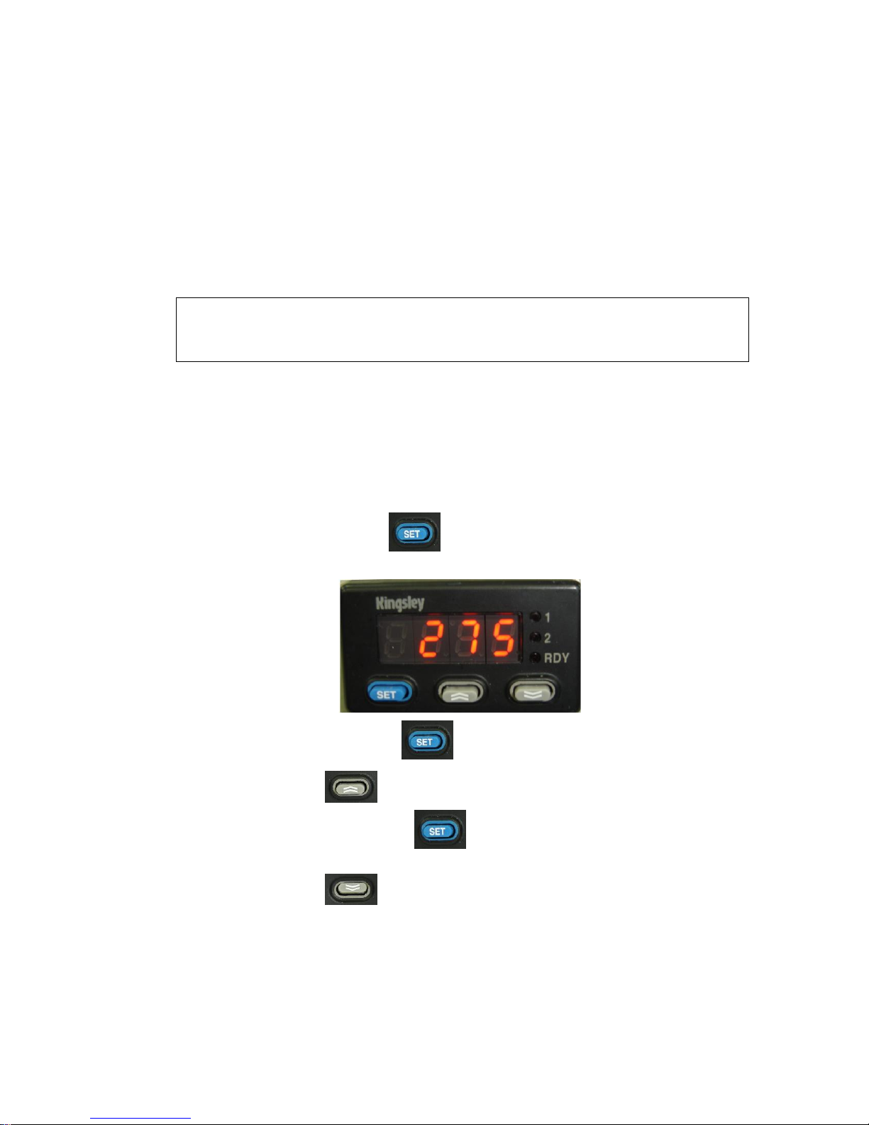
TEMPERATURE SETTING
Temperature controller is set for the unit of measure normally used in your location, F or
C. Kingsley recommends not changing the unit of measure. If you need to make this
change, please contact Kingsley before attempting to do so.
Use the following procedure to change the temperature set point:
NOTE: A single press of key on the temperature control displays the
current set point.
1. Press and hold the key.
2. Press to increase set point.
3. Press and hold the key.
4. Press to decrease set point.
5. When the keys are release, the controller displays the actual temperature
of the typewheel mandrel.
PRESSURE SETTING
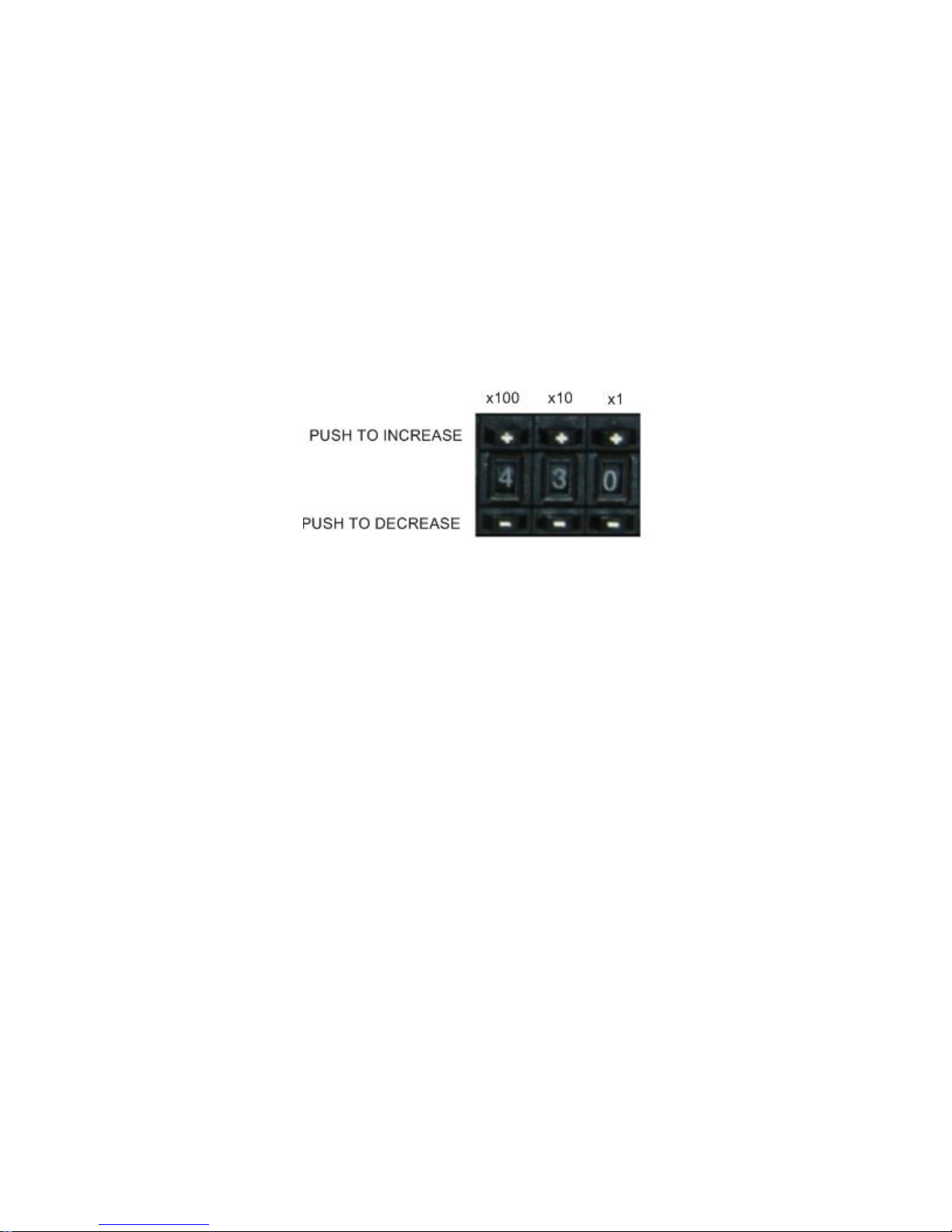
13
Use the following procedure to set the air pressure.
1. Locate the adjusting knob on the air pressure regulator.
2. Gently pull up on the knob to unlock it.
3. Turn the knob clockwise to increase the pressure or counterclockwise to
decrease the pressure.
4. Monitor the pressure gauge and release the knob when the pressure is at
the correct setting.
5. Press down to re-locks the control knob.
DWELL SETTING
To set the dwell
INITIAL TEST
After the initial settings have been programmed, perform an initial manual test. Allow the
machine to warm to the proper operating temperature. Allow an additional 5 minutes to
ensure that the typewheels have heated to the proper temperature.
1. Ensure that the typewheel lock bar is engaged and that the typewheels
cannot rotate.
2. Ensure that the foil is properly threaded.
3. Insert a wire in the wire fixture.
4. Momentarily press the TEST switch on the side of the control box. The
machine imprints the wire.
5. Inspect the wire to determine the quality of the imprint. If the quality
needs improvement, refer to the Troubleshooting section of this manual
(page 21) to determine the necessary adjustments. Follow the
procedures specified to adjust the machine.
6. Once the imprint quality is satisfactory, perform a test run before placing
the wire-marking machine into service.
 Loading...