

KINGSINE KS833 Instruction Manual
KS833 Instruction Manual
roger@kingsine.com.cn
KKSS883333 CCoommpprreehheennssiivvee CCaalliibbrraattoorr ffoorr
EElleeccttrriiccaall
IInnssttrruuccttiioonn M
MMeeaassuurriinngg
Maannuuaall
VVeerrssiioonn 11..00
KKIINNGGSSIINNEE EELLEECCTTRRIICC AAUUTTOOMMAATTIIOON
1
KINGSINE ELECTRIC AUTOMATION CO., LTD.
N
CCOO.
.
,
,
LLTTDD..

KS833 Instruction Manual
roger@kingsine.com.cn
Table of Contents
Chapter1 Brief Introduction .........................................................................................................5
Chapter 2 Functions..................................................................................................................6
Chapter 3 Main Technical Parameters of KS833 Series...............................................................7
3.1 Main Technical Parameters of KS833 (Grade 0.05).................................................7
3.2 Main Technical Parameters of KS833 (Grade 0.1).........................................................9
3.3 KS833 Operation Panel................................................................................................11
3.4 System Configuration...................................................................................................12
3.5 Maintenance & Service ................................................................................................12
Chapter 4 Operation Interface....................................................................................................13
4.1 Welcome Interface........................................................................................................13
4.2 Main Menu...................................................................................................................13
Chapter 5 Multifunction Standard Source..................................................................................15
5.1 Brief Introduction.........................................................................................................15
5.2 Operation Flow.............................................................................................................15
Chapter 6 Instrument Calibration...............................................................................................26
6.1 Set Working Environment ............................................................................................26
6.2 Print Report ..................................................................................................................27
6.3 Input Instrument Attributes...........................................................................................28
6.4 Input Range ..................................................................................................................29
6.5 Types of Calibration .....................................................................................................31
Chapter7 Calibrate Electrical Energy Meters.............................................................................47
7.1 Enter Energy Meter Interface.......................................................................................47
7.2 Booting Test of Electrical Energy Meters.....................................................................50
7.3 Creeping Test of Electrical Energy Meters...................................................................51
7.4 Basic Error Test of Electrical Energy Meters...............................................................51
7.5 Benchmarking Test of Electrical Energy Meters..........................................................52
7.6 Data Processing............................................................................................................53
Chapter 8 Transducer Calibration...............................................................................................54
8.1 Operation Flow.............................................................................................................54
8.2 Calibrate the Nominal Value of Transducer Output......................................................55
8.3 Continue Calibration ....................................................................................................56
8.4 Verify Transducer Measuring .......................................................................................56
8.5 T est Conclusion:...........................................................................................................61
8.6 Stop Test .......................................................................................................................61
8.7 Data Processing............................................................................................................61
Chapter 9. Calibrate Multifunction Standard Source .................................................................62
9.1 Brief Introduction.........................................................................................................62
9.2 Operation Flow.............................................................................................................62
Chapter 10 Connected tests........................................................................................................68
10.1 Functions:...................................................................................................................68
10.2 Operation method:......................................................................................................68
Appendix I..................................................................................................................................70
2
KINGSINE ELECTRIC AUTOMATION CO., LTD.

KS833 Instruction Manual
roger@kingsine.com.cn
Attachment I...............................................................................................................................73
Attachment Ⅱ ...........................................................................................................................74
3
KINGSINE ELECTRIC AUTOMATION CO., LTD.
KS833 Instruction Manual
roger@kingsine.com.cn
Attention
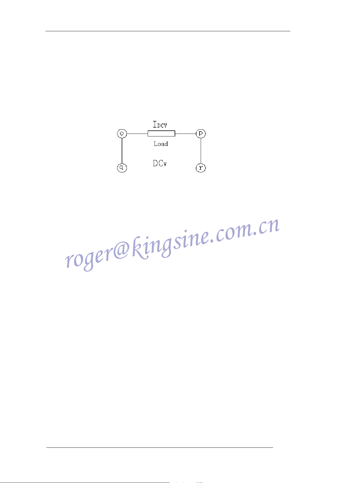
1. For higher output precision, DC voltage output is four-wire output,
the wiring is as follows, and sees Figure 1 for the definitions of o, p, q, and
r.
2. Self-locking will be activated for AC/DC Current/Voltage overload,
if the system gives a prompt of Overload Warning, you will hear alarm
sound at the same time. Press OK, the alarm sound will be stopped. You
can restart the test after correcting the fault. If the system is self-locked,
please turn it off and reboot it.
3. When measuring 2-element active, reactive and power, Ub and Uo
should be shorted.
4. No non-technical person should be allowed to enter the place
when conducting calibration using the standard source, or the instrument
output precision will be affected.
4
KINGSINE ELECTRIC AUTOMATION CO., LTD.

KS833 Instruction Manual
roger@kingsine.com.cn
Chapter1 Brief Introduction
KS833 Comprehensive Calibration Unit for Electrical Measuring Instruments is fully
compatible with the relevant national codes: JJG124-93 Verification Regulation of Ammeter,
Voltmeter & Ohmmeter, GB/T767-1999 Direct Acting Indicating Analogue Electrical
Measuring Instruments and Their Accessories, SD110-83 Inspection Regulation of Electrical
Indicating & Measuring Instruments, JJG440-86 Verification Regulation of Frequency Single
Phase Meters, JJG603-89 Verification Regulation of Pointer Frequency Meters, JJG 307
-1998 Verification Regulation of Verification Equipment for AC Electrical Energy Meter,
JJG596-1999 Verification Regulation of Electrical Energy Meters, GB/T 11150-2001
National Standard of Electrical Energy Meter Inspection Instruments, JJG (Power) 01-94
Verification Regulation of Electrical Measuring Transducers; it applies the latest embedded
system, DSP Very Large Scale field programmable FPGA, advanced software system,
high-power PAM (power amplifier module), large LCD displayer, and imported components
and ICs. With its advanced technology, multi-function, small and portable size, with its
superb performance and strong function, KS833 has been welcomed by our customers.
5
KINGSINE ELECTRIC AUTOMATION CO., LTD.

KS833 Instruction Manual
roger@kingsine.com.cn
Chapter 2 Functions
a) May be used for calibrating indicating instruments, AC acquisition units,
multimeters, FTU, RTU, electrical measuring transducers, and electrical energy
meters;
b) Built-in Grade 0.05 high precision voltage, current, phase, power, power factor,
harmonic meters;
c) Standard output (Grade 0.05) of voltage, ampere, phase, active power,
cross-phase reactive power and real reactive power.
d) Output current, voltage, power, phase and harmonic for closed-loop control, to
ensure low wandering & annual stability rate.
e) Calibrating electrical energy meters (Grade 0.1)
f) Standard output at Grade 0.1 for 1st -19th harmonics, and standard output of Grade
0.2 for 20th -31st harmonics;
g) Work mode: instrument calibration output mode and standard source output
mode;
h) Built-in USB and RS232 interfaces, software upgrading and data transfer can be
done without opening the box;
i) The software can perform self-calibration, and can calibrate the electrical
measuring parameters without opening the box;
j) The software can perform auto fault detector and indicate the defect location;
k) Large LCD display, all Chinese pop-up menus for these operations: 1. rotary
encoder operation, 2. soft touch keyboard operation, and 3. operation under
Windows on PC;
l) Storage capacity up to 1,000 calibrated meters’ data.
m) Through software you can round off the calibrated data, print verification report
and calibration data.
6
KINGSINE ELECTRIC AUTOMATION CO., LTD.

KS833 Instruction Manual
roger@kingsine.com.cn
Chapter 3 Main Technical Parameters of KS833 Series
3.1 Main Technical Parameters of KS833 (Grade 0.05)
a) Output & measure AC voltage
Available steps: 10V, 30V, 100V, 300V, 750V; automatic switch is possible between the
steps.
Adjustment range: Step x (0 – 120)%
Adjustment fineness: Step x 0.01%
Resolving power: Step x 0.01%
Accuracy: 0.05%RG
Stability: 0.01% / 1min
b) Output & measure AC current
Available steps: 100mA, 1A, 5A, 10A, 25A; automatic switch is possible between the
steps.
Adjustment range: Step x (0 – 120)%
Adjustment fineness: Step x 0.01%
Resolving power: Step x 0.01%
Accuracy: 0.05%RG
Stability: 0.01% / 1min
c) Output & measure AC power
Adjustment fineness: Step x 0.01%
Resolving power: Step x 0.01%
Accuracy: 0.05%RG (F>0.5)
Stability: 0.01% / 1min
d) Output & measure AC voltage and current frequency
Frequency range: 45,000 - 65,000Hz
Adjustment fineness: 0.001Hz
Accuracy: 0.01%RD
e) Output & measure AC phase
Phase shift range: 0.00º ~ 359.99º
Resolving power: 0.01º
Adjustment fineness: 0.01
Accuracy: 0.05º
f) Output & measure AC power factor
Output range: -1~0~+1
Measuring accuracy: 0.0005
7
KINGSINE ELECTRIC AUTOMATION CO., LTD.

Adjustment fineness: 0.0001
roger@kingsine.com.cn
g) Output & measure harmonic
Harmonic setting: 2~31
Harmonic content: voltage, current ≤30% (as against fundamental)
st
Harmonic output precision: 0.1% (1
0.2% (20th ~31st ,as against fundamental)
Harmonic phase: 0~360º, adjustable
h) Measure electrical energy
Measuring accuracy: 0.1%RD, PF≥0.5
Volt measuring range: 100V, 220V ,380V
Current range: 0.05 ~ 24A
i) Distortion in AC voltage & current output
< 0.2% (non-capacitance load)
j) Max output load capacity of AC v oltage & current
Voltage output 25VA, current output 25VA
~19th, as against fundamental)
KS833 Instruction Manual
k) Output & measure DC voltage
Steps available: 100mV, 1V, 10V, 30V, 100V, 300V, 750V
Adjustment range: Step x (0 – 120)%, (0%~110% output range at Step 750V)
Resolving power: Step x 0.01%
Adjustment fineness: Step x 0.01%
Accuracy: 0.05%RG
Stability: 0.01% / 1min
l) Output & measure DC current
Steps available: 1mA, 10mA, 100mA, 1A, 5A, 10A, 25A
Adjustment range: Step x (0 – 120)%
Resolving power: Step x 0.01%
Adjustment fineness: Step x 0.01%
Accuracy: 0.05%RG
Stability: 0.01% / 1min
m) Max output load capacity of DC voltage & current
Voltage output 20VA, current output 25VA
n) Measure DC:
Voltage measuring: ±10V
Current measuring: ±20mA
Accuracy: 0.01%RG
o) Reference conditions for parameter test:
Ambient temperature: 22º± 1º
Working temperature: 0º~ 40º, humidity: ≤85%
8
KINGSINE ELECTRIC AUTOMATION CO., LTD.

KS833 Instruction Manual
roger@kingsine.com.cn
Working voltage range: 220VAC±15%,50Hz
3.2 Main Technical Parameters of KS833 (Grade 0.1)
a) Output & measure AC voltage
Available steps: 10V, 30V, 100V, 300V, 750V; automatic switch is possible between the
steps.
Adjustment range: Step x (0 – 120)%
Adjustment fineness: Step x 0.01%
Resolving power: Step x 0.01%
Accuracy: 0.1%RG
Stability: 0.02% / 1min
b) Output & measure AC current
Available steps: 100mA, 1A, 5A, 10A, 25A; automatic switch is possible between the
steps.
Adjustment range: Step x (0 – 120)%
Adjustment fineness: Step x 0.01%
Resolving power: Step x 0.01%
Accuracy: 0.1%RG
Stability: 0.02% / 1min
c) Output & measure AC power
Adjustment fineness: Step x 0.01%
Resolving power: Step x 0.01%
Accuracy: 0.1%RG (PF≥0.5)
Stability: 0.02% / 1min
d) Output & measure AC voltage and current frequency
Frequency range: 45.000 – 65.000Hz
Adjustment fineness: 0.001Hz
Accuracy: 0.02%RD
e) Output & measure AC phase
Phase shift range: 0.00º ~ 359.99º
Resolving power: 0.01º
Adjustment fineness: 0.01
Accuracy: 0.1º
f) Output & measure AC power factor
Output range: -1~0~+1
Measuring accuracy: 0.001
Adjustment fineness: 0.0001
9
KINGSINE ELECTRIC AUTOMATION CO., LTD.

g) Output & measure harmonic
roger@kingsine.com.cn
nd
Harmonic setting: 2
Harmonic content: voltage, current ≤30% (as against fundamental)
Harmonic output precision: 0.2% (as against fundamental)
Harmonic phase: 0~360º adjustable
h) Measure electrical energy
Measuring accuracy: 0.1%RD, PF≥0.5
Volt measuring range: 100V, 220V, 380V
Current range: 0.05 ~ 24A
i) Distortion in AC voltage & current output
< 0.5% (non-capacitance load)
j) Max output load capacity of AC v oltage & current
Voltage output 25VA, current output25VA
k) Output & measure DC voltage
Steps available: 100mV, 1V, 10V, 30V, 100V, 300V, 750V
~31st
KS833 Instruction Manual
Adjustment range: Step x (0 – 120) %, (0%~110% output range at Step 750V)
Resolving power: Step x 0.01%
Adjustment fineness: Step x 0.01%
Accuracy: 0.1%RG
Stability: 0.02% / 1min
l) Output & measure DC current
Steps available: 1mA, 10mA, 100mA, 1A, 5A, 10A, 25A
Adjustment range: Step x (0 – 120)%
Resolving power: Step x 0.01%
Adjustment fineness: Step x 0.01%
Accuracy: 0.1%RG
Stability: 0.02% / 1min
m) Max output load capacity of DC voltage & current
Voltage output 20VA, current output 25VA
n) Measure DC:
Voltage measuring: ±10V
Current measuring: ±20mA
Accuracy: 0.02%RG
o) Reference conditions for parameter test:
Ambient temperature: 22º± 1º
Working temperature: 0º~ 40º, humidity: ≤85%
Working voltage range: 220VAC±15%,50Hz
p) Size:
10
KINGSINE ELECTRIC AUTOMATION CO., LTD.

450mm×380mm×180mm
roger@kingsine.com.cn
q) Weight:
20kg
3.3 KS833 Operation Panel
a —— Phase A - AC current output terminal - positive
b —— Phase A - AC current output terminal - negative
KS833 Instruction Manual
Figure 1 KS833 Operation Panel Interface
c —— Phase B - AC current output terminal - positive
d —— Phase B - AC current output terminal - negative
e —— Phase C - AC current output terminal - positive
f —— Phase C - AC current output terminal - negative
g —— DC current output terminal - positive
h —— DC current output terminal - negative
i —— Photo-electronic socket for calibrating electrical energy meters
j —— Grounding port
k —— Phase A - AC voltage output terminal - positive
l —— Phase B - AC current output terminal - positive
m —— Phase C - AC voltage output terminal - positive
n —— Common low terminal for three-phase AC voltage
o —— DC voltage input terminal - positive
p —— DC voltage input terminal - negative
q —— DC voltage output terminal - positive
r —— DC voltage output terminal - negative
s、t
—— Transducer (DC input measuring)
11
KINGSINE ELECTRIC AUTOMATION CO., LTD.

3.4 System Configuration
roger@kingsine.com.cn
KS833 Instruction Manual
KS833 Comprehensive Calibrating Unit for Electrical Measuring
Instruments - host
Operating software for KS833 Comprehensive Calibrating Unit for
Electrical Measuring Instruments
Cable 1 cable
Test wire for power industry 1 parcel
Special serial port cable 1 cable
Operating Instruction 1 copy
Al-alloy package 1
Portable computer (optional) 1 set
Matrix printer and printer cable (optional) 1 set
Computer software for instrument calibration (optional) 1 set
1 unit
1 set
3.5 Maintenance & Service
Three-year guarantee of free repair of the host unit, and life-long maintenance for the
equipment. Free software update and free training. Please refer to the printer manual for
printer operation instructions.
12
KINGSINE ELECTRIC AUTOMATION CO., LTD.

KS833 Instruction Manual
roger@kingsine.com.cn
Chapter 4 Operation Interface
4.1 Welcome Interface
The following welcome interface will be displayed on start, press ENTER to go to the
main menu.
4.2 Main Menu
Figure 2 Welcome interface
Figure 3 Main menu
4.2.1 Brief Introduction
Six items are displayed on the main menu, you can select them by the following steps:
press direction keys or turn the Rotary Encoder to move the cursor on the button you want,
13
KINGSINE ELECTRIC AUTOMATION CO., LTD.

KS833 Instruction Manual
roger@kingsine.com.cn
then press ENTER or press down the Rotary Encoder to enter corresponding menu;
henceforward the above operations will be referred to as “press down xx button” in short.
Press down “Transducer” button to enter transducer system setting; press down
“Instrument Calibration” button to enter KS833’s function module of instrument calibration;
press down “Standard Source Calibration” button to enter KS833 standard source
calibration; press down “Standard Source” button to enter KS833 standard source; press
down “Connected test” to connect to host (upper) computer, which then controls the unit;
press down “Upgrade Software” button to upgrade the software.
14
KINGSINE ELECTRIC AUTOMATION CO., LTD.
KS833 Instruction Manual
roger@kingsine.com.cn
Chapter 5 Multifunction Standard Source
5.1 Brief Introduction
KS833 multifunction standard source is composed of six parts: DC Standard Source,
Single Phase Standard Source, Phase Standard Source, Three-phase Standard Source,
Power Standard Source and Harmonic Standard Source; the interface is shown as below in
Figure 4:
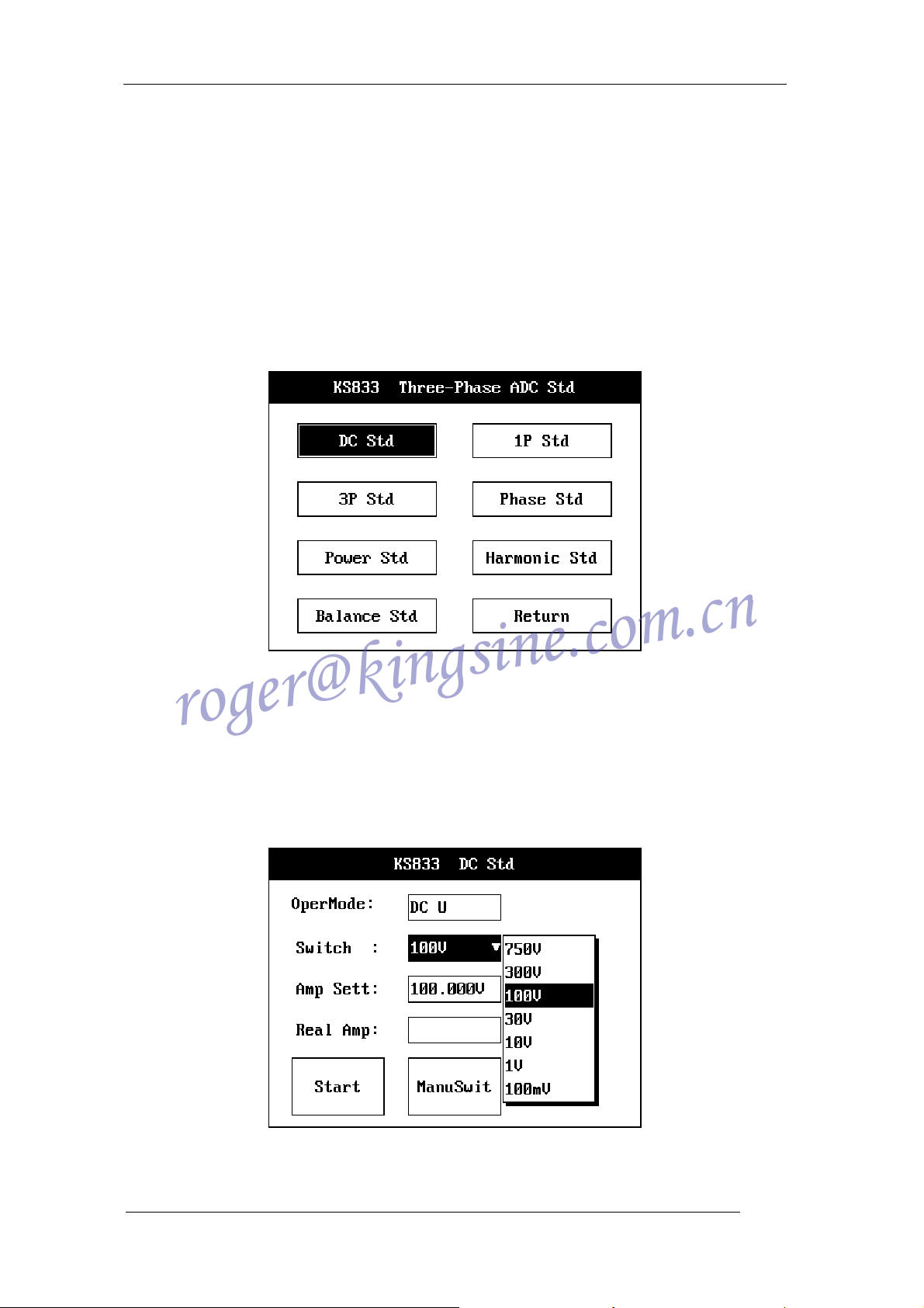
Figure 4 KS833 Standard Source main interface
5.2 Operation Flow
5.2.1 Select Standard Source in the Main Menu to enter selections, click the button to
select standard sources, or click Return to go back to Main Menu
Figure 5 KS833 DC Standard Source interface
15
KINGSINE ELECTRIC AUTOMATION CO., LTD.

KS833 Instruction Manual
roger@kingsine.com.cn
5.2.2 DC Standard Source: see Figure 5 for its interface
5.2.2.1 Select output mode
Click the “Operation Mode” dropdown box, select “DC Voltage” or “DC Current.” When
you select “DC Voltage” or “DC Current”, the output amplitude tagtext will automatically
switch into output voltage or output current. The working amplitude tagtext will automatically
switch into actual output voltage or output current. Working Step can switch between volt
steps and amp steps according to different operation modes.
5.2.2.2 Select Working Step
Click on volt steps or amp steps (depending on different operation modes) and select
the step you want, take into mind to select the step value closest to output value so that you
can get higher output precision. Or turn on the Auto Switch to let the system select the step
with highest precision according to output amplitude.
5.2.2.3 Set Voltage & Amp amplitude
In the edit box of Output Voltage or Output Current, input the volt or amp value you
want the instrument to output. The applicable volt and amp range is 0%~120% (0%~110%
output range at DC Voltage – Step 750V), anything exceeding the range will be
automatically truncated by the system.
5.2.2.4 Auto Switch & Manual Switch
Click Auto Switch button to toggle between auto switch and manual switch. When you
enter Manual Switch, you can select working step by the Working Step dropdown box.
When you enter Auto Switch, the Working Step dropdown box will be inaccessible, the
system will automatically select working step for the user according to the input amplitude
value.
5.2.2.5 Instrument Output
Click on “Start Test” button, a dialogue box will pop up, click OK to confirm and start test.
After test starts, the button’s tagtext changes into Stop Test; the cursor’s input center moves
to Stop Test button. The system will, according to the Step amplitude, increase 1%
progressively until it reaches the output value. During the output increasing process, you
can click Enter to stop test at any time; the detailed procedure is the same as that of Stop
Test.
5.2.2.6 Real-time Closed Loop Calibration
During the test, the instrument can automatically calibrate the output according to the
load connected into it.
5.2.2.7 Actual Output Display
During test, the system can automatically collect actual output data and display it as it is
at the moment in the text box for actual voltage (or actual current).
5.2.2.8 Overload Warning
During test, the instrument can automatically check its own load and the load
connected into it, if the connection load exceeds its output load, the system will close all
output and then give an overload warning; at the same time it will prompt the user with
overload phase and sound alarm. You can click OK in the dialogue box to stop the alarm.
You can restart the test after eliminating the fault.
5.2.2.9 Stop Test
When output is not needed from the instrument, you can click Stop Test button to stop,
16
KINGSINE ELECTRIC AUTOMATION CO., LTD.
KS833 Instruction Manual
roger@kingsine.com.cn
and the tagtext on the button will change into Start Test, a prompt for starting next test;
meanwhile, the cursor’s input focus changes to Start Test button. The system will,
according to the Step amplitude, decrease 1% progressively until the output becomes zero.
During the process to stop test, the user cannot click Enter to cancel Stop Test; if you want
to output again, you have to wait till after test stops and then click Start Test button to restart
test output.
5.2.2.10 On-line Adjustment
During test, the user can change output value at any time according to needs. Steps:
move the cursor to Volt amplitude (Amp amplitude), click Enter to modify the amplitude, click
Enter again, the instrument will step change the output to new amplitude. After that the
same as Start Test, start closed loop calibration.
5.2.2.11 Return
Click Return to return to the upper page.
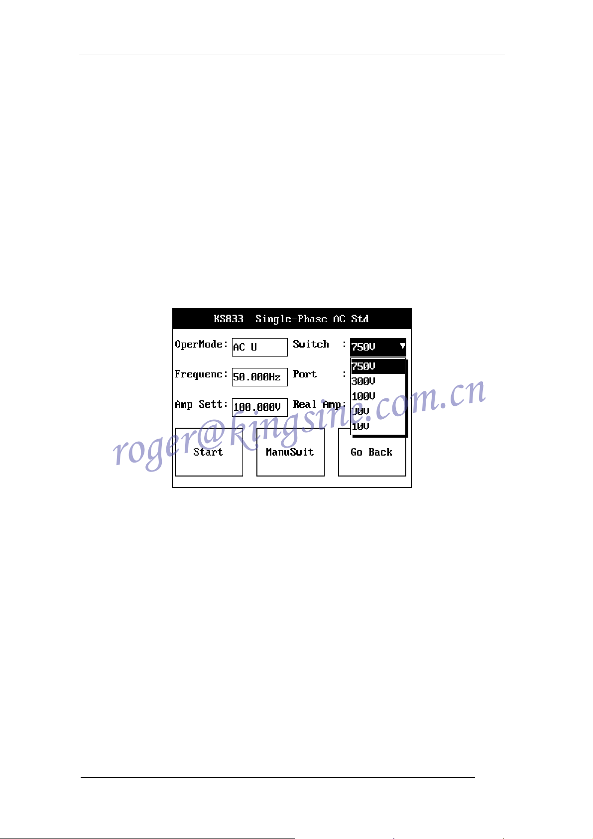
5.2.3 Single Phase AC Standard Source, see Figure 6 for its interface (Phase A output)
Figure 6 KS833 Single Phase AC Standard Source interface
5.2.3.1 Same test procedure as that of DC Standard Source.
5.2.3.2 The text box of Output Port will display the amplitude of output voltage or current.
5.2.3.3 Set Working Frequency
You can set working frequency before test starts or during test. The frequency may
change between 45Hz and 65Hz. The actual output amplitude will not be affected when you
set the frequency.
5.2.4 Phase Standard Source: see Figure 7 for its interface
17
KINGSINE ELECTRIC AUTOMATION CO., LTD.
KS833 Instruction Manual
roger@kingsine.com.cn
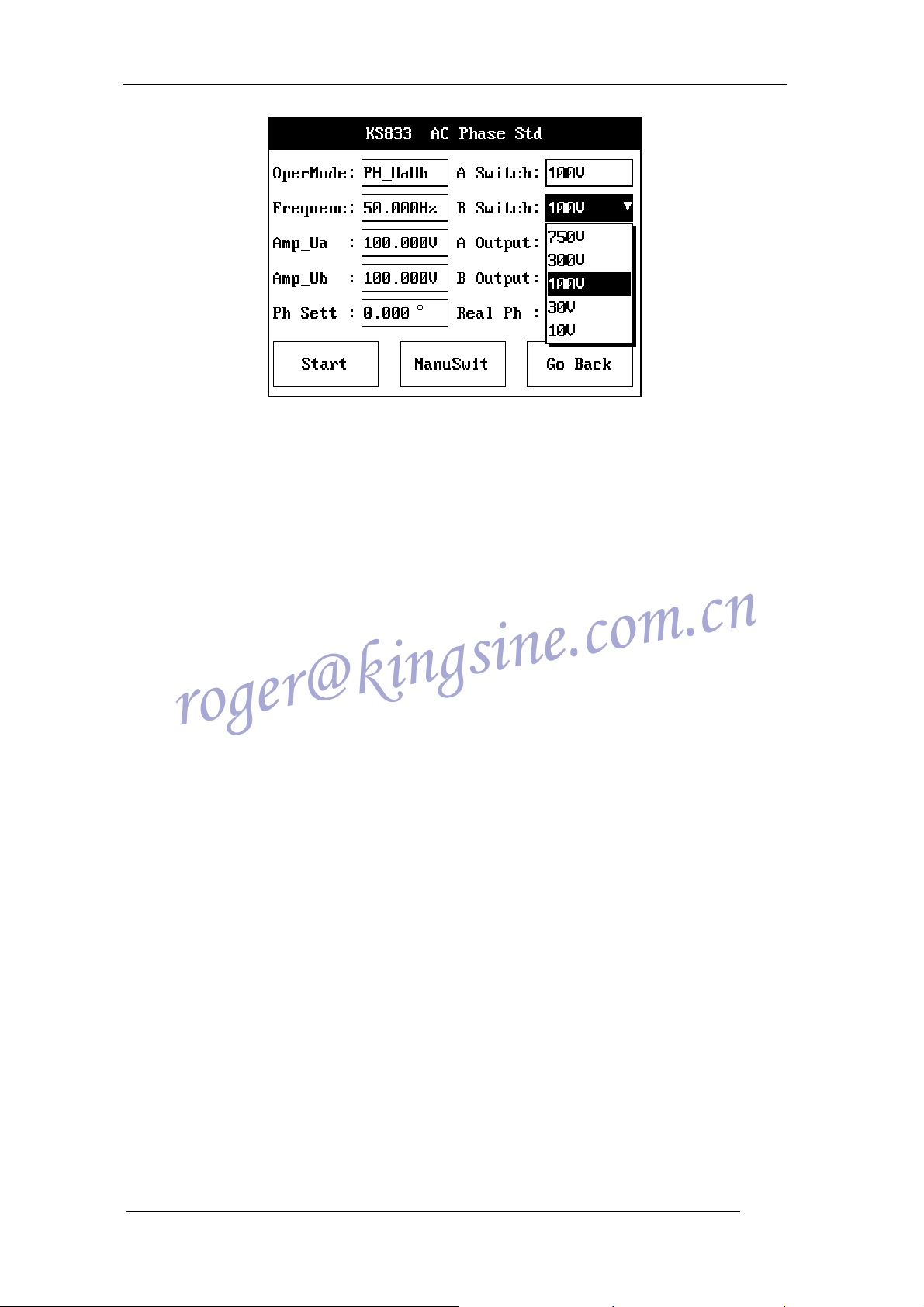
Figure 7 KS833 AC Phase Standard Source interface
5.2.4.1 Select Operation Mode
Click the “Operation Mode” dropdown box, select Ua Ub Phase, Uala Phase or lalb
Phase positions. The instrument will output the voltage or ampere at the corresponding
output terminal, the difference between two phases will be the phase value you need.
5.2.4.2 Select Working Step
Click Phase A Step and Phase B Step or volt step or amp step (depending on different
operation modes) and select the step you want, take into mind to select the step value
closest to output value so that you can get higher output precision. Or switch on the Auto
Switch to let the system select the step with highest precision according to output amplitude.
5.2.4.3 Set Phase Value
In the edit box for output phase you can input the phase value you want the instrument
to output. Phase range: 0°~360°, the system automatically switch it into 0°~360° according
to the user’s input.
5.2.4.4 Auto Switch & Manual Switch
Click Auto Switch button to toggle between auto switch and manual switch. When you
enter Manual Switch, you can select step switch by the Working Step dropdown box, at the
same time the edit box for inputting amplitude will be shielded. When you enter Auto Switch,
the Working Step dropdown box will be inaccessible, the system will automatically select
working step for the user according to the input amplitude value.
5.2.4.5 Instrument Output
Click Start Test button. Then Start Test button becomes unavailable, the tagtext
changes into Testing; at the same time Stop & Void button becomes available, the tagtext
changes into Stop Test. The system will step increase by 10° progressively until it reaches
the output value.
5.2.4.6 Real-time Closed Loop Calibration
During the test, the instrument can automatically calibrate the output according to the
load connected into it.
5.2.4.7 Actual Output Display
During test, the system can automatically collect actual output data and display it as it is
at the moment in the text box for actual phase.
5.2.4.8 Overload warning: identical as 5.2.2.8
18
KINGSINE ELECTRIC AUTOMATION CO., LTD.
KS833 Instruction Manual
roger@kingsine.com.cn
5.2.4.9 Stop Test: identical as 5.2.2.9
5.2.4.10 On-line Adjustment
During test, the user can change output value at any time according to needs. Steps:
move the cursor to output phase, click Enter to modify the amplitude, click Enter again, the
instrument will step change the output to new amplitude. After that the same as Start Test,
start closed loop calibration.
5.2.4.11 Return
Click Return to return to the upper page.
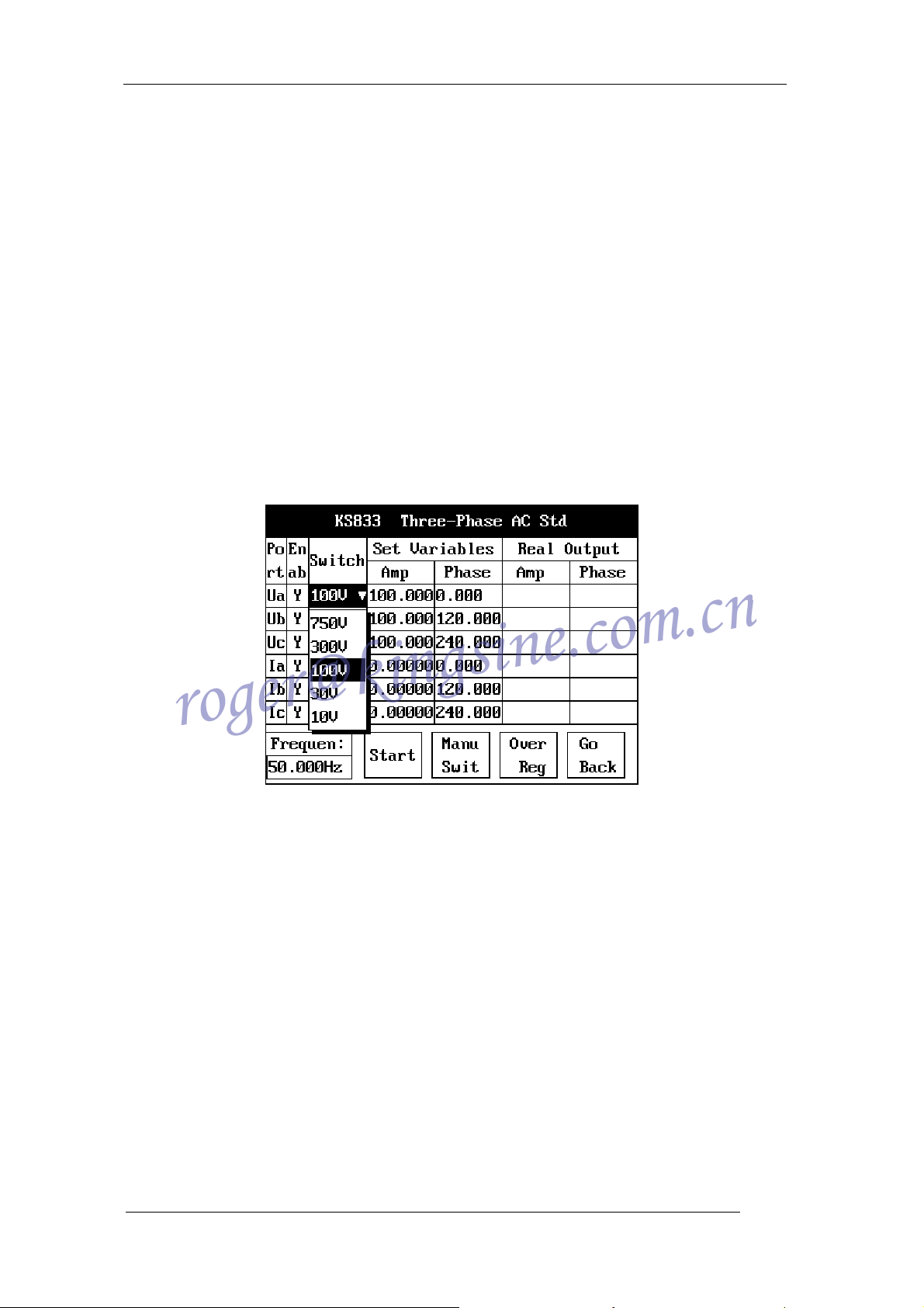
5.2.5 Three-phase Standard Source: see Figure 8 for its interface
5.2.5.1 Select Output Port
Click Enter of your selection button, when the selected button displays “Yes”, which
indicates the corresponding output port is effective, the instrument will be able to output
voltage or current at that output port. When a “No” displayed, it indicates ineffectiveness of
that output port and hence no output at that port. Of which the Ua output port cannot be
changed, and it is always effective.
Figure 8 KS833 Three-phase AC Standard Source interface
5.2.5.2 Change Working Step
Click Enter on the dropdown box of Working Step to select the working step you want,
the selected Step is effective only for the corresponding output port, and different output
ports and output simultaneously under different working steps.
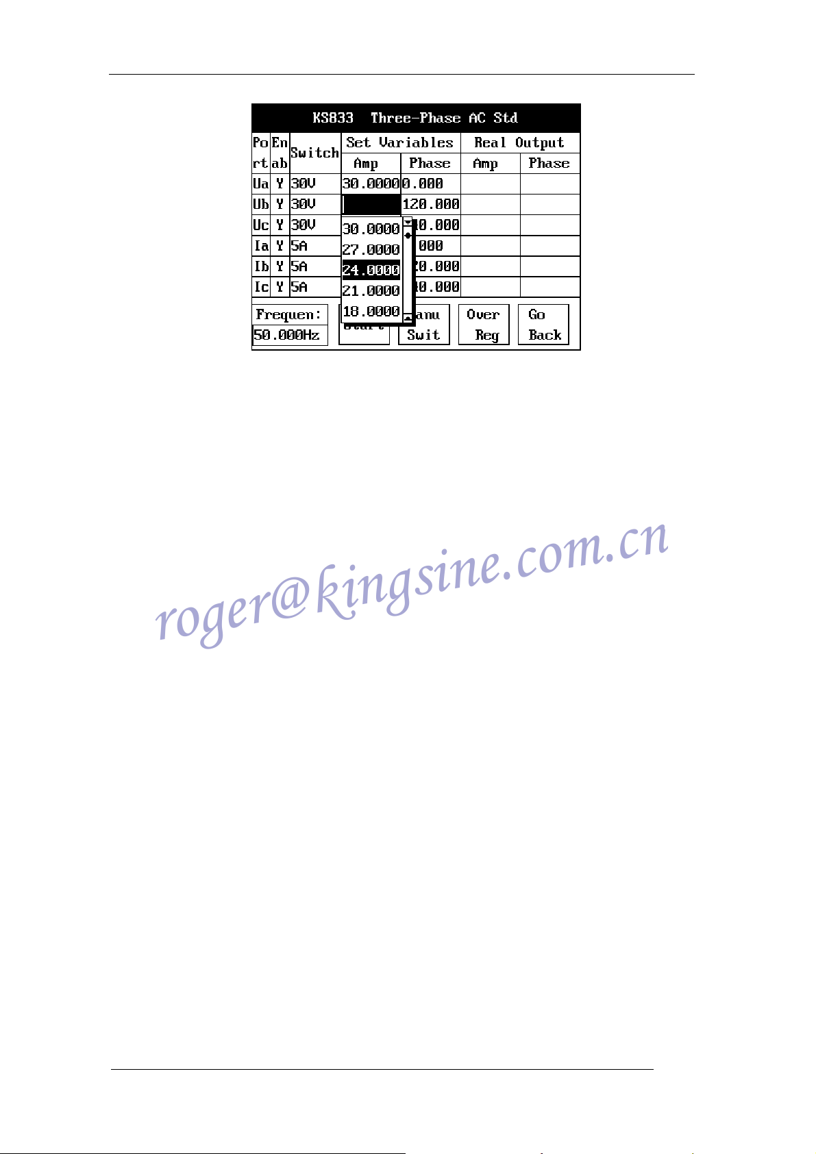
5.2.5.3 Set Output Amplitude and Phase Of Voltage & Current
Input the amplitude and phase you want in the columns under variable output (in the
same way as that of Single Phase Standard Source and Phase Standard Source). You may
also use dropdown menu to input the amplitude and phase preset by the program (Remark:
Ua’s amplitude cannot be zero). Take the amplitude of Ub as an example:
19
KINGSINE ELECTRIC AUTOMATION CO., LTD.
KS833 Instruction Manual
roger@kingsine.com.cn
Figure 9 Input variable under Three-Phase Standard Source
Move cursor to the set place and click Enter, then click “DOWN” of the direction keys,
you’ll see a dropdown menu as Figure 9; select the value you want by using the direction
keys and click Enter to confirm.
5.2.5.4 Set Working Frequency
Set the working frequency you want in the edit box of Working Frequency
(45Hz~65Hz).
5.2.5.5 Auto Switch & Manual Switch
Click Manual Switch button to toggle between manual switch and auto switch. When
you enter Manual Switch, you can switch working steps in the dropdown box of Working
Step column; when you enter Auto Switch, the dropdown box of Working Step will not be
usable, and the system will automatically switch working steps according to the amplitudes
set by the user. Manual Switch & Auto Switch are effective to all output ports simultaneously.
5.2.5.6 Overall Regulating & Phase Regulating
When the system displays Overall Regulating, the voltage & amp amplitudes of the
three phases are equal. For instance, if you change Ua amplitude in Figure 9 into 20V, then
Ub and Uc amplitudes will automatically changed into 20V. Click “Overall Regulating”, the
key will turn into “Phase Regulating.” In Phase Regulating, there can be different amplitude
for different phases. (Remark: in Overall Regulating, the phases will automatically have a
difference of 120 degrees between them.)
5.2.5.7 Start Test
Click Start Test button, the instrument will output the voltage and current of each port in
sequence according to step length. And the output value at the moment will be displayed in
the text boxes of the amplitude and phase columns under Actual Output.
5.2.5.8 Real-time Closed Loop Calibration
During the test, the instrument can automatically calibrate the output according to the
load connected into it.
5.2.5.9 On-line Adjustment: identical as 5.2.4.10
5.2.5.10 Fine Adjustment
Move cursor to the edit boxes of amplitude or phases, then turn the selection encoder,
the figures will increase or decrease by step length of its minimum position.
5.2.5.11 Overload Warning
20
KINGSINE ELECTRIC AUTOMATION CO., LTD.
KS833 Instruction Manual
roger@kingsine.com.cn
During test, the instrument can automatically check its own load and the load
connected into it, if the connection load exceeds its output load, the system will close all
output and then give an overload warning; at the same time it will prompt the user with
overload phase and sound alarm. You can click OK in the dialogue box to stop the alarm.
You can restart the test after eliminating the fault.
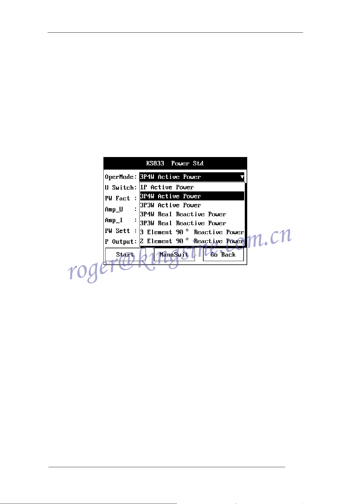
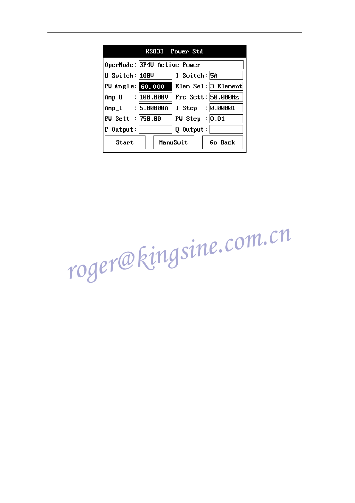
5.2.6 Power Standard Source: see Figure 10 for its interface
5.2.6.1 Select Operation Mode
Click the dropdown box of Operation Mode to select different power output modes,
which are available in seven modes: “3P4W Active Power” (3P4W short for “3 Phase 4
Wire”), “3P3W Active Power”, “1P Active Power”, “3P4W Real Reactive Power”, “3P3W
Real Reactive Power”, “3 Element 90° Reactive Power”, “2 Element 90° Reactive Power.”
Figure 10 KS833 Power Standard Source interface
5.2.6.2 Change Working Step
Click enter on the dropdown box of Volt step and Amp step, select the working step you
want (the standard source provides 3 volt steps: 750V, 300V, 100V; and 5 amp steps: 25A,
10A, 5A, 1A, 100mA.)
5.2.6.3 Select Power Factor
Click enter on the dropdown box of Power Factor, press “DOWN” of the direction keys
to select the power factors you want (5 power factors are available in the standard source:
1.0, 0.5, 0.8L, 0.5C, 0.8C.) You can also use the built-in small keyboard to input other power
factors, refer to the appendix for instructions on how to use the small keyboard.
5.2.6.4 Toggle Between Power Factor and Phase Angle
Move cursor to the Power Factor dialogue box, click rotary encoder to toggle to
Power Phase Angle, you can input value by using the numerical keyboard. (Remark:
Power Factor and Phase Angle may have different corresponding relation under different
operation modes.)
21
KINGSINE ELECTRIC AUTOMATION CO., LTD.
KS833 Instruction Manual
roger@kingsine.com.cn
Figure 11 Power Phase Angle toggle interface
5.2.6.5 Element Selection
When the user selects operation modes other than 1P Active Power, then Element
Selection is available; when 1P Active Power is selected, Element Selection will not be
applicable. When Element Selection is activated, the user may select different output
elements (default is Combined Element Output)
5.2.6.6 Select Volt Amplitude
When the user selects a volt step, the standard source provides three output voltages
under the step, which are: 380V, 600V and 750V output under Step 750V; 150V, 220V and
300V output under Step 300V; 57.735V, 75V and 100V under Step 100V. The user may also
manually input the value by using the numerical keyboard in the instrument panel.
5.2.6.7 Set Frequency
The user may change the working frequency in the frequency input edit box. The
frequency may change between 45Hz and 65Hz.
5.2.6.8 Set Current
When the user select a amp step, the standard source provides 10 output currents
under the step, which are: 25A,22.5A,20A,17.5A,15A,12.5A,10A,7.5A,5A and 2.5A
output under Step 25A; 0A,9A,8A,7A,6A,5A,4A,3A,2A and 1A under Step 10A; 5A,
4.5A,4A,3.5A,3A,2.5A,2A,1.5A,1A and 0.5A output under Step 5A; 1A,0.9A,0.8A,
0.7A,0.6A,0.5A,0.4A,0.3A,0.2A and 0.1 under Step 1A; 100mA,90mA,80mA,
60mA,50mA,40mA,30mA,20mA and 10mA output under Step 100mA. The user may also
manually input the value by using the numerical keyboard in the instrument panel.
5.2.6.9 Power Setting
Set the output power in the power input edit box. The maximum value for power setting
is, under the corresponding output voltage, the actual output power when the current output
is 120% of the Amp step; the exceeded part will be truncated by the system automatically.
When you have selected element test, due to the effect of power factor, the element’s power
will be zero under all voltage and current. Therefore when the user inputs the element’s
power, the display is zero, which only implies that it is zero under the effect of power factor,
voltage and current outputs are still there during test, so you can only modify the amplitudes
of current or voltage but you cannot modify power.
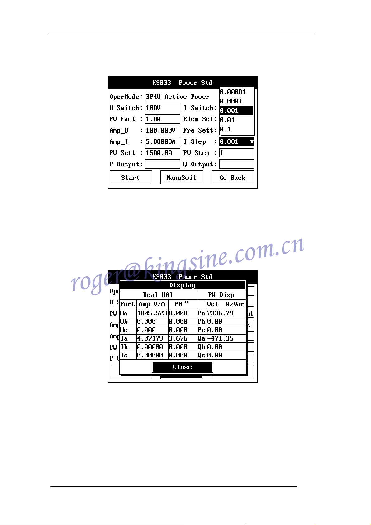
5.2.6.10 Set Stepping
70mA,
22
KINGSINE ELECTRIC AUTOMATION CO., LTD.
KS833 Instruction Manual
roger@kingsine.com.cn
Set Stepping is divided into Amp step Length and Power Step Length, each has 4 steps,
whose value is determined by the Volt step and Amp step. The figure shows the Amp step
Length under 100V & 25A.
Figure 12 Set Stepping in Power Standard Source
Click Start Test and turn the rotary encoder during test, as it turns cell by cell, the
changed amplitude will set the step length.
5.2.6.11 Instrument Output Display
Click enter on the Output Display button, the system will display the actual output
amplitudes and phases of all ports at the moment, as well as the active power & reactive
power of all elements.
Figure 13 KS833 Output Power Display Interface
5.2.6.12 Auto Switch & Manual Switch
Click Auto Switch button to toggle between manual switch and auto switch. When you
enter Manual Switch, you need to switch amp steps to enhance the precision of power
output. When you enter Auto Switch, the Amp Step dropdown box will be unavailable, the
system will automatically switch amp steps according to the power set by you, while at the
same time you have to switch the volt step and volt amplitude.
5.2.6.13 Start Test
Click the Start Test button; the instrument will directly output volt amplitude & phase as
23
KINGSINE ELECTRIC AUTOMATION CO., LTD.
 Loading...