

KINGSINE K68i, K68 Instruction Manual
roger@kingsine.com.cn
K68i / K68 Relay Tester
Instruction Manual
Version: 1.3
Kingsine Electric Automation Co., Ltd.

K68 Series Protection Relay Test Set
roger@kingsine.com.cn
Dear Customers:
Thank you for using Kingsine Series Relay Tester. We hope the technical data and information in
the manual can be provided to you for use and operation as detailed as possible. Meanwhile, we
shall be appreciated highly if experts, technicians and readers can give us your precious comments.
If you need business consultation or technical support service, please call us or visit our website.
Oversea Trade : +86-755-8341 8941
Customer Service: +86-755-8835 2590
Website : http://www.kingsine.com.cn
Email : roger@kingsine.com.cn
Note:
This manual is applicable for KINGSINE K68i and K68 Relay Tester but it is compiled to use K68i
as example. The corresponding updated software and functions instruction will be released on our
website (www.kingsine.com.cn), when updating the software and increasing the contents. In order
to obtain the latest and first-hand information, please pay more attention to the latest news on our
website. The functions and pictures mentioned in this manual will be as reference only and the
released real product is the sole standard.
1

Catalogue
roger@kingsine.com.cn
Chapter 1 Overview.............................................................................................................................3
1.1 System Description................................................................................................................3
1.2 Technical Parameters.............................................................................................................4
1.3 Amplifier for Voltage and Current .........................................................................................7
1.4 Package list ............................................................................................................................7
1.5 After service:..........................................................................................................................7
1.6 Attention:................................................................................................................................8
Chapter 2 Panel Description ................................................................................................................9
Chapter 3 Testing Operation ..............................................................................................................12
3.1 Main Menu...........................................................................................................................12
3.2 Basic Operations..................................................................................................................13
3.3 DC Relays Testing................................................................................................................15
3.4 AC Relays T esting................................................................................................................20
3.5 Distance/ Zero-sequence Relays Testing .............................................................................26
3.6 Harmonic Output Testing.....................................................................................................37
3.7 Frequency Protections Testing .............................................................................................41
3.8 Aux DC ................................................................................................................................48
Chapter 4 System Calibration, Settings & Update.............................................................................49
4.1 System Calibration...............................................................................................................49
4.2 IP Setting..............................................................................................................................55
4.3 Software Upgrade and Report Upload.................................................................................57
- 2 -

1.1 System Description
roger@kingsine.com.cn
K68 Series Relay Tester is new All-in-One protections testing systems developed
independently by KINGSINE on the basis of Windows CE system, which adopts the
embedded system, the latest high-speed DSP processor and ultra-large-scale field
programmable logic devices FPGA.
It have high-precision signal and high-efficiency and high-stability power amplifier with
the advanced level in the world by the developed digital phrase lock patented algorithm and
SPWM technology based on the advanced SOC design concept, to provide customers with
comprehensive and easy-to-use testing solutions with complete functions.
It is widely applied to power industry, metallurgy industry, petrochemical industry, railway
K68 Series Protection Relay Test Set
Chapter 1 Overview
and scientific research institution as well as industrial and mining enterprises and power
equipment factories that on a large scale.
Characteristics:
1. High power: 3 x 0…35A with a power of 450VA for Medium/Low Voltage test.
2. Phase, frequency and amplitude are independently and continuously adjustable.
3. The maximum output of DC voltage for every phase:300V
4. High Precision: 0.14% reading+0.06% range guaranteed at 0-35A & 0.14% reading+0.06%
range guaranteed at 0-300V.
5. Auto/Manual Test on all its five modules: DC Test, AC Test, Distance Test, Harmonic Test,
Frequency protection.
6. 3-Years Warranty for free repair.
7. Reliability: Self-protection by stop output plus with light flashing/sound alarming in case
of wrong-wiring, open/short-circuit, overheat & overload.
8. On-site Testing Convenience: the equipment can be put vertically or horizontally when
on-site testing.
9. The tester could upgrade by USB and can make speed data communication between
computer On 100M-T Network-card.
10. Internal design is of architectural style framework and of shock & impact resistance
external box made of high intensity aluminum alloy enables the equipment subject to rigid
vibration.
3

K68 Series Protection Relay Test Set
roger@kingsine.com.cn
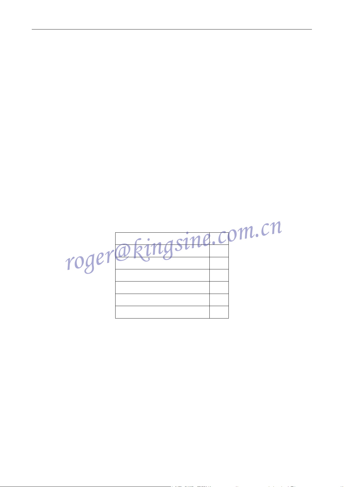
K6 Series Protection Relay Tester main Tech description
Factor
(DC Module Setting)
(Interface Setting)
Binary Input 8 pairs ● ●
Binary Output 4 pairs ● ●
Model
K68 K68i
AC Current I 3*35A 3*35A
AC Voltage U 4*130V 4*300V
DC Current I 3*20A 3*20A
DC Voltage U 1*150V 1*150V
DC Voltage Ubc 1*300V 1*300V
Aux. DC
0~300V 0~300V
Aux. DC
0~260V 0~300V
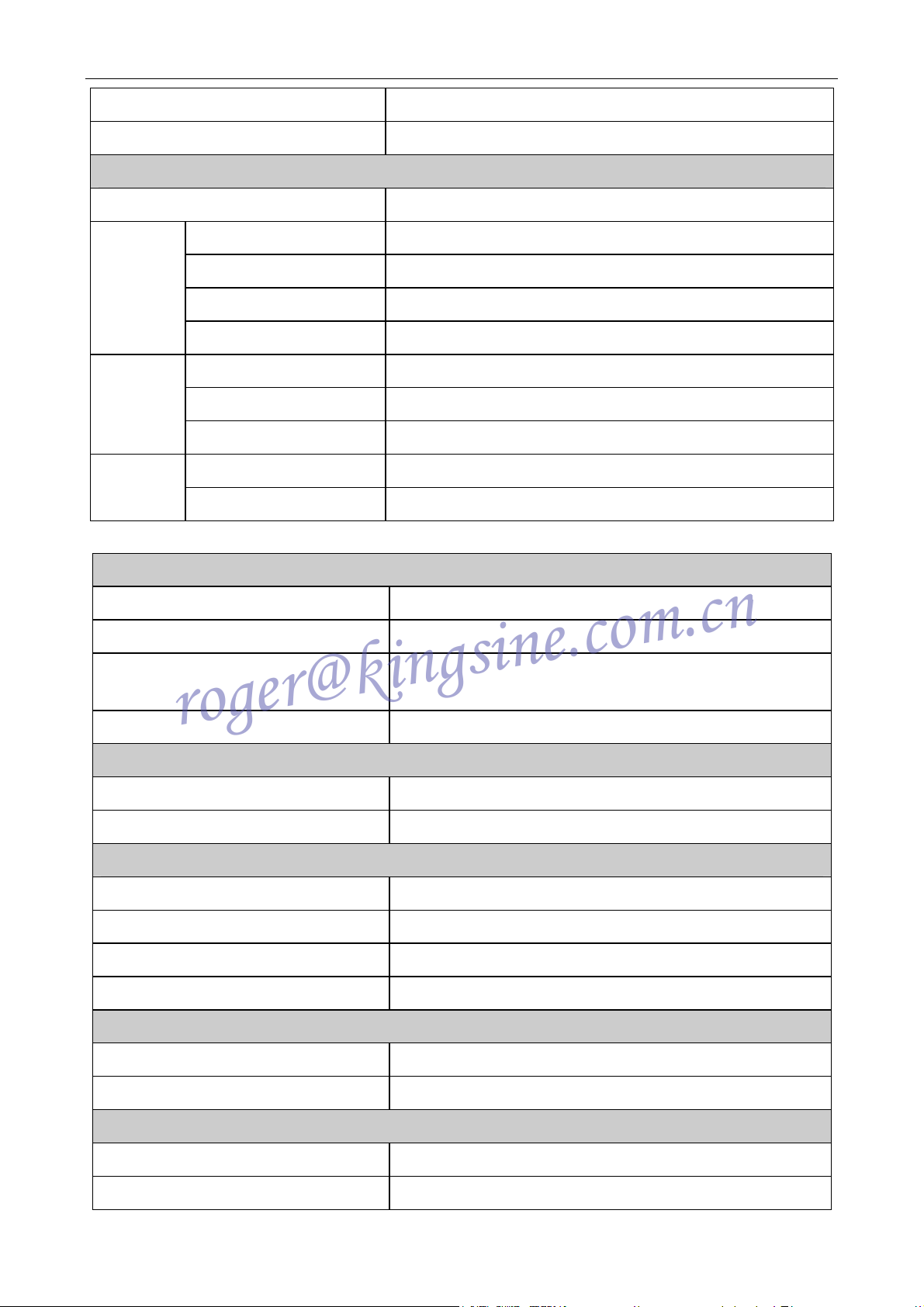
1.2 Technical Parameters
Voltage generators (overload and short protection)
Setting
Range
Power
Accuracy
Rise/down time
Resolution
Setting
Range
Power
4-phase AC (L-N)
2-phase AC (L-L)
4-phase AC (L-N)
2-phase AC (L-L)
<0.14% reading + 0.06% range guaranteed at 0-300V;
<0.04% reading + 0.01% range typical at 0-300V
Current generators ( O/C protection)
3-phase AC (L-N)
1-phase AC (3L-N)
3-phase AC (L-N)
1-phase AC (3L-N)
4x 0 ... 300 V
2 x 0 ...600 V
4 x 110VA, max. at 0 ... 300V
2 x 220VA, at 0 ... 600 V
<120µs
1mV
3 x 0 ... 35A
1 x 0 ... 105A
3 x450 VA max.
1 x 900VA, at 0 ... 105A
Accuracy
<0.14% reading + 0.06% range guaranteed at 0-35A;
<0.05% reading + 0.02% range typical at 0-35A;
4
K68 Series Protection Relay Test Set
roger@kingsine.com.cn
Rise/down time
Resolution
Voltage and Current Synchronism
Range
Accuracy / drift
Frequency
Harmonic superimpose
Resolution
Range
Phase
Accuracy / drift
Resolution
Range
Timer
Accuracy / drift
<50µs
1mA
Generators, general
≤10μS
0 ... 1000 Hz
Error < 0.001Hz at 0 ... 50Hz
2-9 orders
0.001Hz
0° ... 360°±0.2°
Error < 0.2 °
0.01°
0.1mS ... 9999.999S
Error<0.1ms
Voltage ranges
Current ranges
Accuracy
Resolution
Ranges
Accuracy
Number
Resolution
Time range
Ranges
DC generators (over-load protection)
0 ... 300V/180VA
0 ... 20A (60A on 3-phase-paralleling)/300VA
<0.14% reading + 0.06% range guaranteed at 0…20A;
<0.05% reading + 0.02% range typical at 0…20A;
1mA; 1 mV
Aux DC supply
0~300V/0.5A
Error<0.5%
Binary inputs
8 pairs (extendible to 64channel)
0.1ms
0.1mS -9999.999S
10V ... 250V
Binary outputs
Number
Ranges
DC-250V/3,AC-250V/3A
4 Pairs
Power supply
Nominal input voltage
Power
5
220V±10% VAC, 1-phase
1000VA/Max.15A

K68 Series Protection Relay Test Set
roger@kingsine.com.cn
Nominal frequency
Working temperature
Storage temperature
Humidity range
Box
Weight
Dimensions
Interface
50/60±10% Hz
Environmental conditions
-5°C... 55 °C
-20°C... 75 °C
5 ... 90 %, non-condensing
Alloy aluminum
24KG
360(D)×140 (W) ×460 (H) mm
RJ 45, USB,RS232, PS/2,VGA
6
K68 Series Protection Relay Test Set
roger@kingsine.com.cn
1.3 Amplifier for Voltage and Current
Current generator and voltage generator have no current booster and no voltage booster, but direct
coupling mode is adopted by them, which enables the power supply’s frequency output range to be
from 0Hz to 1000Hz, outputting DC and all AC voltage or AC current in all frequency. Such as
square waveform, varying waveform in proportion with the exponential function as well as mixed
Reclosing waveform. Basically it meets the transient testing requirements of the protection device,
thereby achieving the simple simulating test on various protection devices.
Power amplifier circuit has the perfect protective function against over-current, over-voltage and
over-temperature so that keep the high-power components of the set from damage in the test. When
the power amplifier is charged, the internal circuits of protection relay will real-time monitor/detect
the output current value from the voltage circuit and determine whether the detected current values
are overload. When there is overload or short-circuit in the circuit voltage, the power of the power
amplifier will shut down automatically and the test will stop, giving out the warning signal.
1.4 Package list
Relay-Tester mainframe 1set
Operation software 1set
Twisted-pair 2pc
Special testing cables 1kit
Power cord 1pc
Instruction Manual 2pcs
Aluminum alloy packaging box 1pc
1.5 After service:
The Host will have free maintenance for three years. While the 3-year guarantee for free repair shall
be subject to the condition that the ‘products’ shall not be modified or improperly used within three
years after being sold. In order to improve continually on the reliability and performances of the
hardware and software of the test device, welcome all customers to bring forward valuable
comments and suggestions on this product. We will be happy to work with you and explore and
strive to meet your requirements.
7

K68 Series Protection Relay Test Set
roger@kingsine.com.cn
1.6 Attention:
z There are good Grounding picture in the right bottom of each interface menu.
The grounding link is abnormal if showing picture
In order to insure the test security and the accuracy of testing result, please check the power
supply whether the grounding is proper.
z It is prohibited to connect the host instrument with 380V three-phase AC or DC power supply.
z Before testing, the grounding line jack must be reliably grounding; otherwise it might damage
the Relay Tester.
z The voltage circuit can not be short circuit or overload, and the load of the current circuit
should meet Impedance values under the given technical parameters so that avoid the overload
affecting the testing results.
z In case that there is overload or short-circuit in the voltage generator, the Relay Tester will
automatically shut down the power of the amplifier power and give out warning signal.
Maximum current load in each phase is up to 0.55A for the voltage generator.
z In case that the large current has been output for a long time, and as a result, the power
amplifier’s temperature is at high degrees, the Relay Tester will automatically shut down the
power of the amplifier power and give out warning signal, User shall stop test right until the
amplifier power gets cool.
z Binary Input’s potential is directional. So better to use idle contact as usual.
z Negative terminals A, B, C of Binary input are all connected together, but not connected with
the public terminal ‘N’ of voltage / current output terminal and the ground wire (such as panel,
machine box) that is the suspending ground. Binary Input’s terminal is compatible with the idle
contact and the potential (10-250V). However, Binary Input’s terminal has directionality for the
input of the charged contact, as shown in the Figure below, A, B, C and R are connected with
the high potential (+),the negative terminal are connected with the lower potential (-) of the
charged contact, and then the computer can detect the overturn of the contact state. If the
connections are in reverse, what will always be detected will be the closed state.
z If there is emergency in the process of the test, the Power Amplifier button must exit rapidly
and then to shut down the power of the host of Relay Tester.
8
K68 Series Protection Relay Test Set
roger@kingsine.com.cn
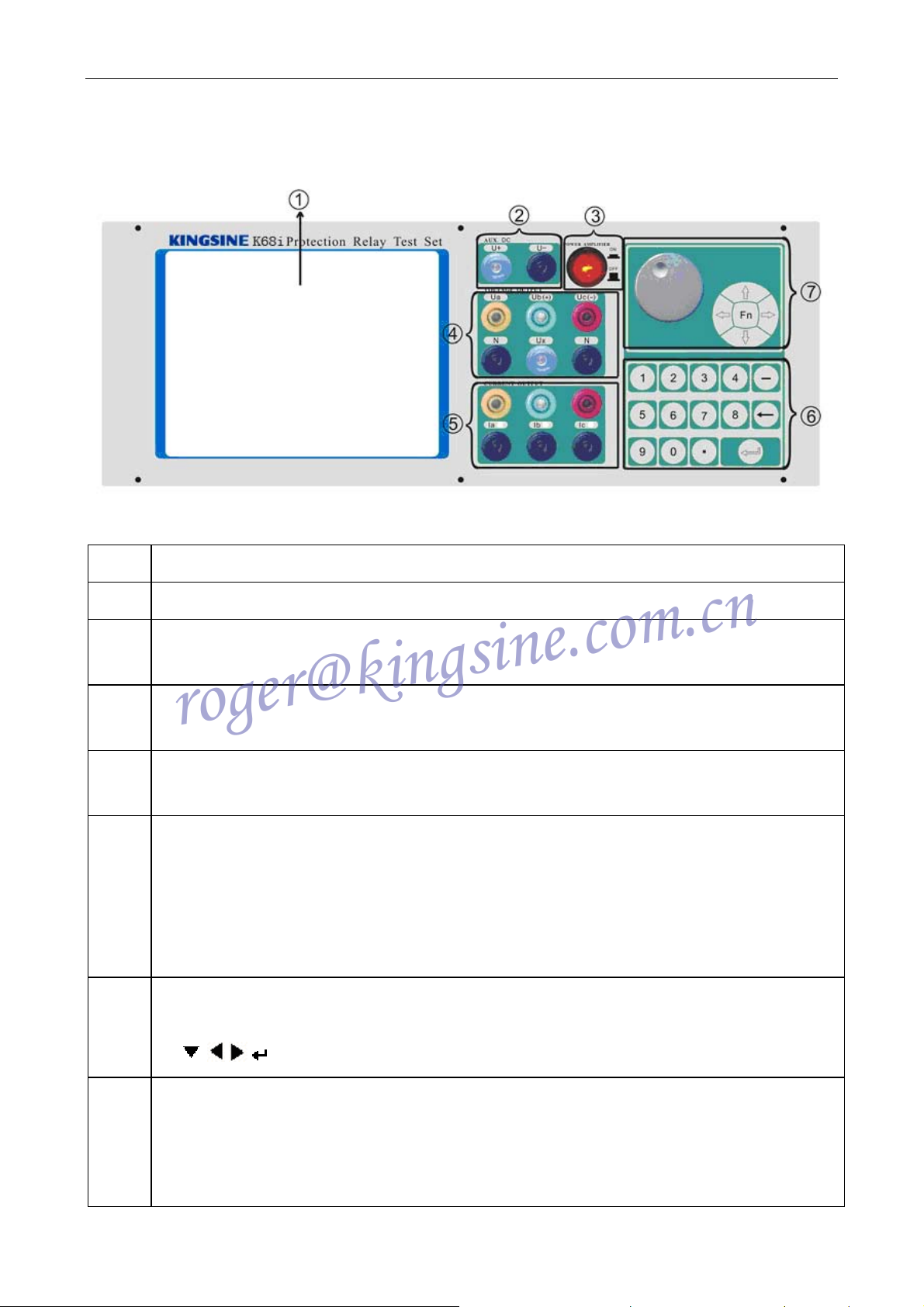
Chapter 2 Panel Description
(1)
(2)
(3)
(4)
(5)
(6)
Fig. 2-1 Panel Description
6.4” TFT LCD screen
U(+) and U(-) are for Aux. DC supply,
Power amplifier button: Press the button to start amplifier, while amplifier stop
working the moment the button revert.
UB and UC are applied for programmable DC output of DC module. UN terminal is
electrically connected.
Both AC current and DC current can be output from Current output terminals. IN
terminal is electrically connected.
Functional keyboard: the numeric keys from 0 to 9 are worked for changing the
data of the testing menu. When inputting the data, user should firstly point to the
data position which to be modified with the mouse, and then click the confirm
button. Previous data get cleared and then input new data. After the input please
click confirm button.
Rotary encoder: clockwise move cursor to left and anticlockwise move cursor to left
(7)
(8)
and pressing down or Fn Key for enter. It can be substituted for the button
, , , on the function keyboard.
▲,
Binary Input contact:
1) Public terminal TN corresponds to binary Input contact A, B, C, and TN is electrically
connected.
2) Binary contact are compatible with idle contact and charged contact, Potential +
9

K68 Series Protection Relay Test Set
roger@kingsine.com.cn
terminal of charged contact is supposed to connect to public terminal TN (HN).
10
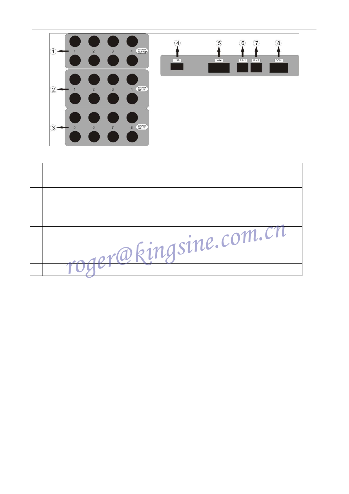
1 Binary Output
roger@kingsine.com.cn
2 Binary Input
3 Binary Input
K68 Series Relay Tester
Fig. 2-2 Panel Description
4
USB interface,is meant to be external connective to various
5 VGA interface, is meant to be external connective to various VGA display
6 PS/2 mouse or keyboard, is meant to be external connective to PS/2 mouse or
keyboard at one time
7 RJ45 interface, is meant to have data transmission between network and computer;
8 COM4
11
K68 Series Relay Tester
roger@kingsine.com.cn
Chapter 3 Testing Operation
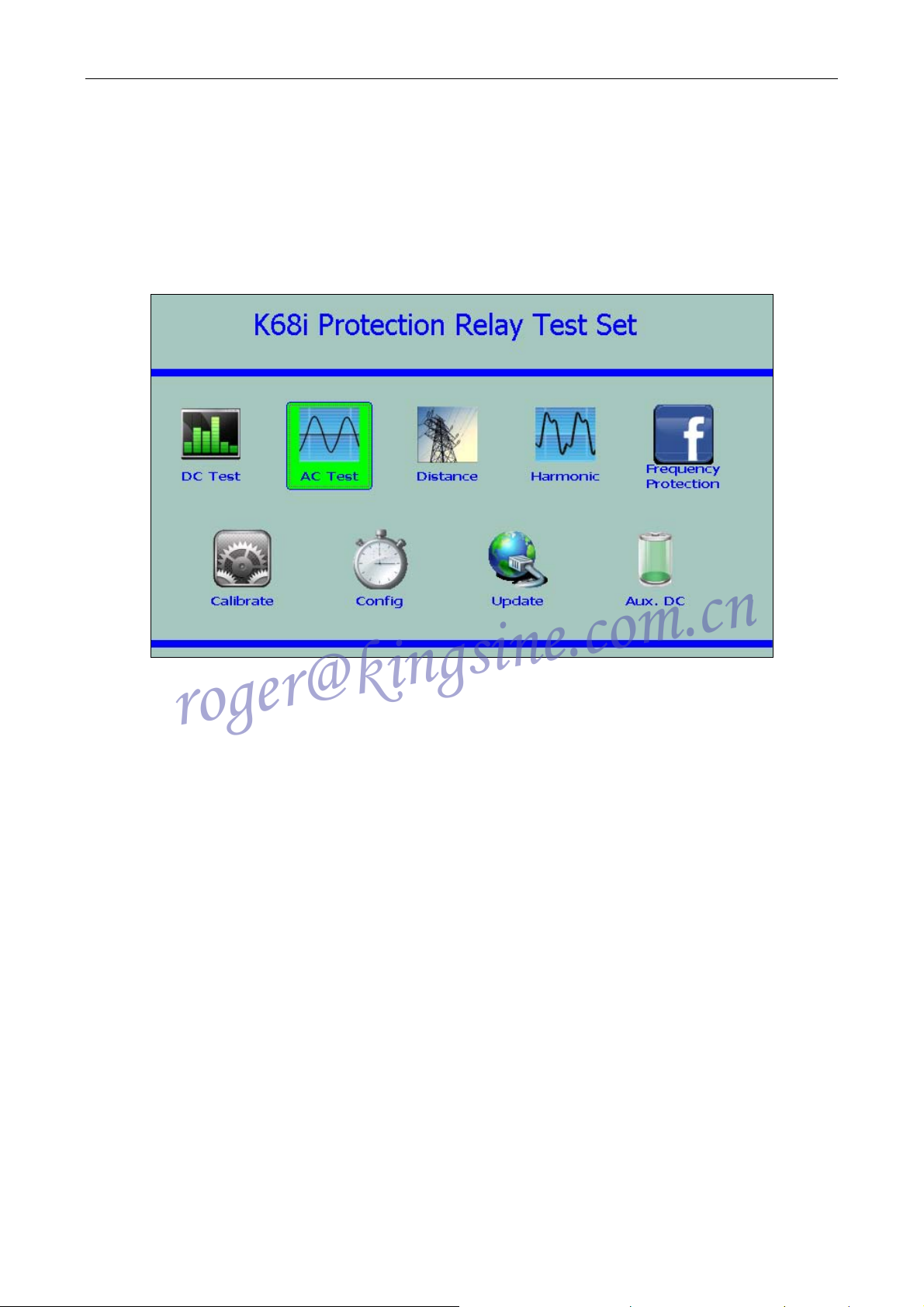
3.1 Main Menu
The main interface of user Operation is shown as below after set software start running:
Fig 3.1-1 Main menu
Users may choose to enter the function modules required with the Rotary encoder or mouse and can
also switch to choose the function modules with the first shortcut key or the direction key on the left
of the external keyboard and then press ‘Enter’ to enter.
DC Test DC Relays Testing
AC Test AC Relays Testing
Distance test the Property of the whole set on circuit protection, such as the
distance relays and zero-sequence relays
Harmonic control Relay Tester and output AC and DC and harmonic to test
automatically and manually, and the oscillogram is used for real-time
monitor of every output channel.
Frequency Frequency protection and test the action value, action time, df/dt
action value, the closed value of voltage and the lockout value of
current of various frequency relays and Low Frequency Decrease
Load automatic device.
Remarks: The Main menu contains the information: name, version number, function modules,
12

K68 Series Relay Tester
roger@kingsine.com.cn
company name, website and telephone of the current system. The reference of the first edition of
K68i Instruction such as software upgrade or content supplement. The real function should refer to
the set latest version as software upgrading.
3.2 Basic Operations
(1) Run
Click ‘Run’ button and begin to this test.
(2) +
Click ‘+’ manual increase button and the chosen variable are increased gradually in
accordance with the set step length.
(3) -
Click ‘-’ Manual decrease button, and the chosen variable is decreased gradually in
accordance with the set step length.
(4) PgDn
Click ‘PgDn’ button, and switch to another Parameter Setup interface.
(5) Save
Click ‘Saver’ button, spring out ‘Save parameter’ interface. In the interface of ‘Save
parameter’, save the tested parameters or import the tested parameters previously saved
and delete parameters.
(6) Report
When springing out ‘Report processing’ interfaces, save, View or delete a report.
(7) Bin. Input
Binary Input: the potential of the electric volume of the input switch has directionality,
under the normal circumstance, you had better use the dead contact. A, B, C negative
terminals of Binary Input terminals are all connected together, and not connected with
the public terminal ‘N’ of voltage and current output terminal and the ground wire (such
as panel, machine box) that is the suspending ground. Binary Input terminal is
compatible with the dead contact and the potential (10-250V). However, the input with
electric contact has directionality (refer to the attentions in 1.6 above for the detail).
(8) Bin. Output
Binary Output: the impulse signal can be triggered from the Relay Tester, to start some
functions of the protection device and reach synchronous or delay timing.
(9)Load
13

Switch the light load and heavy load of the Relay Tester. Under the normal
roger@kingsine.com.cn
circumstances, the Relay Tester outputs light load; when the impedance value is greater
with load or the greater current is output in the Relay Tester; it is proposed to switch the
state of the heavy load before testing.
(10)Exit
Exit this module and Return to the Main menu of the system.
(11)Fn
Press ‘Fn’ function key can jump the Cursor to the bottom function control key and step
to next key.
K68 Series Relay Tester
14
K68 Series Protection Relay Test Set
roger@kingsine.com.cn
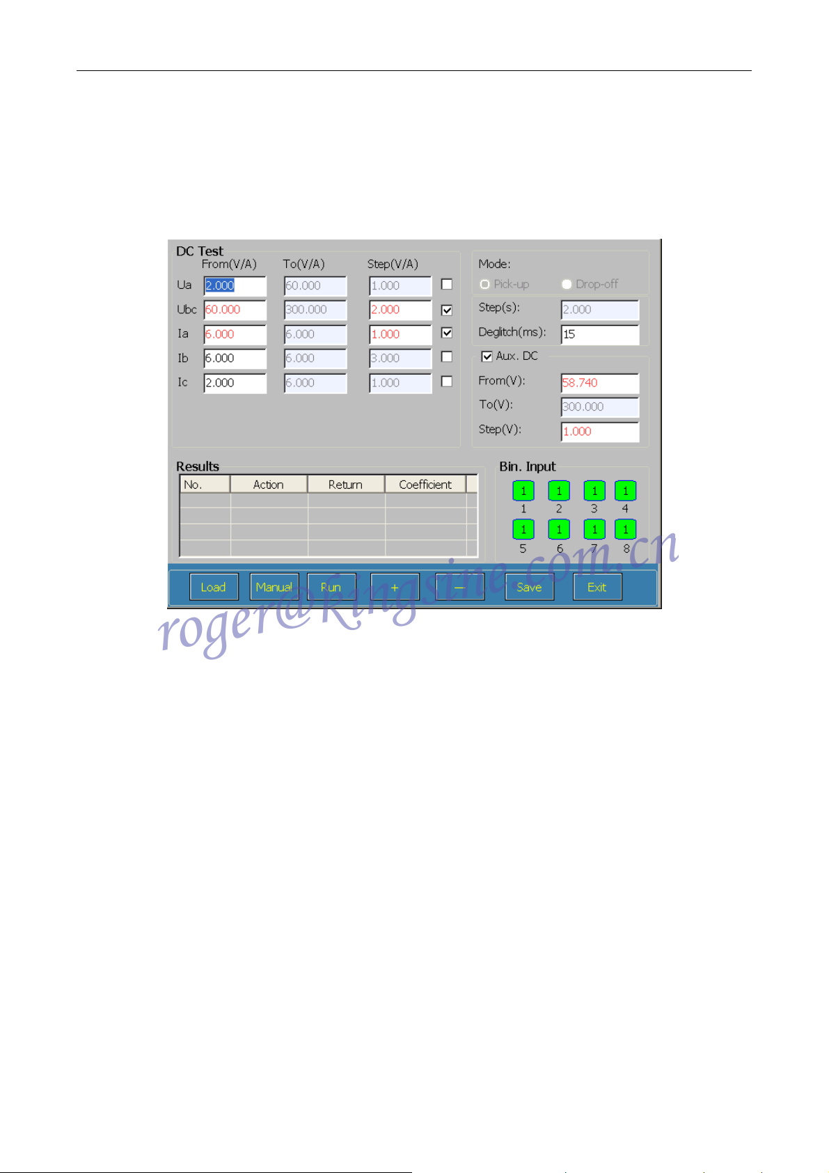
3.3 DC Relays Testing
Click‘DC Test’ module of the Main menu and enter Direct Current interface, This Module test
manually and automatically action value and return time of AC current/Voltage relay as shown in
Fig. 3.3-1:
Fig. 3.3-1 DC Relays Testing
3.3.1 Interface Introduction to the set
There are 3 areas in the Main:
① Left upper area of the interface: You can set the starting value, the final value and step size for
each variable value of the tested AC and DC voltage and current. There are a 4 voltage
channels and 3 current channels in the area, including DC 0-150V voltage output from
UA, UB, UC port and DC 0-300V voltage output from Ub (+) and Uc (-) port. And
0-20A DC current is output from IA, IB, and IC. Click ‘√’of the option box of
‘variable’ with the mouse, as indicates the variables will the variable tested.
② On the left upper area of the interface: The setup area for testing parameters:
③ On the lower area of the interface: It displays the open or close state of Binary Input or Binary
Output and it is the display column of tested results.
15

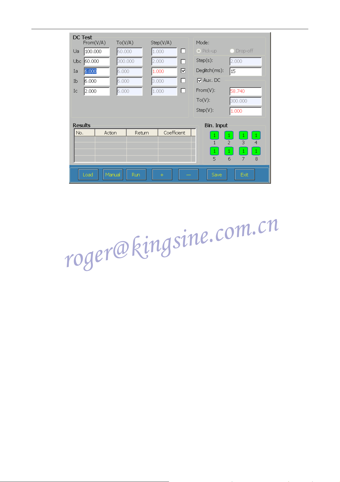
K68 Series Protection Relay Test Set
roger@kingsine.com.cn
Fig. 3.3-2 DC Relays Testing
3.3.2 Parameter setup of the set:
Variable : including Amplitude Value, phase and frequency, one of which can be chosen as a
variable and eight channels(five-way voltage and three-way current)of which can also
be chosen as variable output.
Test mode: including Automatic test and manual testing mode.
Auto: Control Action value, Return Value and Return Coefficient of the testing variables through
setting variable mode, automatic test time and variable step size. When testing, the
variable will increase or decrease by degrees from the starting value to the final value in
accordance with automatic time and step size; when doing an excessive test, set step
size to the positive and the starting value set must be less than the final value; when
doing an inadequate test, set step size to the negative and the starting value set must be
more than the final value. Note: Click ‘Stop’ button to stop the test and then amend the
parameters to retest if a new test is required by changing the parameters in the
automatic test.
Manual : Control the test manually by variable step size of ‘+’ Manual increase or‘-’ Manual
decrease. When testing, the change of the variable will not be controlled by the change
time and not be limited by the final value, step size will not be set to the negative, and
the test of increase or decrease by degrees can be done by +Manual increase and
-Manual decrease; when Binary Input receives the action signal and then the test stops,
16

K68 Series Protection Relay Test Set
roger@kingsine.com.cn
meanwhile, action time and action value are recorded. After testing, the setup
parameters will be changed to re-test without clicking ‘Stop’ button to stop the test, for
the parameter can be changed directly.
Mode : Only adapt to Automatic test, including ‘Action stops’ and ‘Action returns’ mode.
Pick-up: Variables change to strop from the starting value to the final value in accordance with step
size or receive the protection signal to stop the testing process in the process of the
change. Action time and Action value will be automatically recorded and action value
or Return Value of the variable can be tested.
Drop-off : Voltage or current variables change from the starting value to the final value in
accordance with step size, when the protection action signal is received, the variable
will begin to return to the starting value until return signal is received, when Action
stops, action time, action value, return value and return coefficient will be recorded.
Action value, return value and return coefficient will be automatically tested.
Steps(s): when automatically testing, the time of step size changes once for the variable, the
automatic time generally set should be more than Action time and Return Time of the
relay, Maximum Automatic testing time is set to 1000s. When manually testing, users
can grasp the changing time.
Deglitch(s): JitterBuffer time, Deglitch(s) generally can be set to 15ms, it functions when the tested
result is affected due to the jitter of the protection access point in the process of testing
during automatic test, only after the lasting period when the access point is closed or
disconnected meets the set time, the located state is authorized.
3.3.3 Testing process
Click ‘DC Test’ module with the mouse and enter the interface shown in Fig. 3.3-3:
17
K68 Series Protection Relay Test Set
roger@kingsine.com.cn
Fig. 3.3-3 Direct Relays Testing
1) Testing connection
Connect the testing terminals of the relay or the protection device to be tested with the
corresponding output port of the current or voltage by wire and connect the contact of the
relay or the output contact of the protection device with Binary Input port of the Relay Tester
by wire. (Note: DC voltage is output from Ub (+) and Uc (-) port and DC current is output
from IA and In).
2) Parameter setup
A. Set testing mode, including Manual test and Automatic test.
B. Set variables and the starting value and the final value of variables.
C. Set Binary Input (Digital input) and time mode.
D. Set ‘Light load’ or ‘Heavy load’ according to the testing load bulk of the Relay Tester.
E. Save Parameters.
F. Run.
G. Report processing and choose whether to save the report.
3) T esting process
Click on ‘Run’ button to begin the test and click ‘stop’ key if pausing the test in
Operation. In the process of manual test, the parameters of the variable can be changed. If it is
the automatic test, the parameters cannot be changed. Manually press ‘+’ and ‘-’ to make the
relay operate if it is the manual test, when action value and action time are recorded. When
clicking ‘stop’, the test ends and Save Report dialog box is automatically sprung out. Press
18

K68 Series Protection Relay Test Set
roger@kingsine.com.cn
‘Save’ to save results and ‘View’ to preview the selected testing report.
19
 Loading...