

KingShield TXPIR400, TXPIR400W Installation Instructions Manual
Installation Instructions
for Xenon Floodlight
with PIR
TXPIR400 / TXPIR400W
IMPORTANT
This product should be installed by a competent
person and in accordance with the current IEE
Wiring Regulations. If in doubt, consult a qualified
electrician.
This floodlight is provided with an infrared
detector. The detector senses ‘Warmth
movement’ in the surrounding area and
when it is dark. When movement is detected
the lamp will come on. This fitting has no
manual override.
INSTRUCTIONS
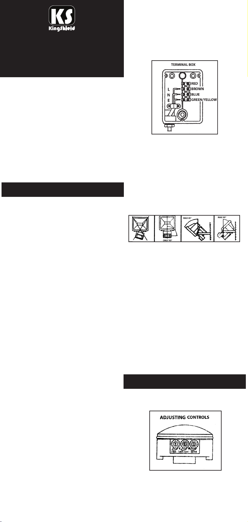
ELECTRICAL WIRING
pen the terminal box cover and
O
nscrew the inlet gland and remove
u
the sealing ring. Thread the power
cable through the inlet gland and the
sealing ring.
Fig. 1
Live = Brown/Red
Neutral = Blue/Black
Earth = Green and Yellow
Insert the wire ends into the terminal
block and then tighten them. Replace
the box cover, screw in the inlet
gland together with the sealing ring.
Switch the power off before installation
to prevent electric shock.
NOTE 1.
On installation try not to install light
fitting close to a vent such as a vent
from a boiler or tumble dryer as hot
air movement can cause the lamp to
switch on when it is not required to.
NOTE 2.
Passing cars (warm engines) and
nearby trees and bushes can cause
your lamp to switch on, due to a
sudden change in temperature and
gusts of wind. Please bear this in
mind when deciding on where to
install your light.
NOTE 3.
Do not mount the fitting in the ceiling.
NOTE 4.
Please ensure the distance between
the front glass of the lamp and the
surface area the lamp is lighting is at
least 1 metre apart.
1. The lamp fitting can be installed using
the three holes on the mounting
bracket. The bracket should be
horizontally fixed, see Fig. 2.
INSTALLING THE LAMP TUBE
Fig. 2
1. Unscrew the bolt and open the glass
holder. Fit the tube into the tube
socket. Keep the waterproof rubber
pad in its original position and close
the glass holder with the bolt.
2. When replacing the lamp - isolate
the fitting from the supply before
opening the glass front. If the lamp
was recently turned off do not touch
the lamp tube with bare hands.
Please follow lamp manufacturers
instructions when fitting the lamp.
3. If glass cover becomes cracked,
replace immediately before using the
lamp again.
OPERATION
The infrared detector is equipped with
three adjusting controls, see fig 3
below.
Fig. 3
2. Loosen the supporter bolts to adjust
the installation angle of the lamp in
accordance with the lighting direction
needed. The lighting direction cannot
be adjusted downwards more than
O
, see Fig. 2.
45
Time Control
The time adjustment control (on the
left) adjusts the lighting period of the
lamp after the detection of movement.
This period is adjustable from 9 secs to
0 mins. Turn the control clockwise to
1
increase the lighting period and
anti-clockwise to reduce the lighting
period.
aylight Control
D
The daylight control adjusts the level of
daylight the infrared detector becomes
ctivated at, so that it can detect. Turn
a
the control clockwise to decrease the
lighting value so the light will come on
later in the evening. Turn the control
nti-clockwise to increase the lighting
a
value so the light will come on earlier in
the evening.
Sensitivity Control
The sensitivity control adjusts the
sensitivity of the detector. Turn the
control clockwise to increase sensitivity
and anti-clockwise to decrease it.
TESTING
By setting the time and daylight controls
to fully anti-clockwise a daylight walk-by
test can be performed to check operation
in daylight after the initial installation.
TROUBLE SHOOTING
• On installation please do not fix the
lamp under a roof or under trees, as
he lamp can light up during daylight
t
hours.
• If your lamp suddenly stops working,
he bulb or fuse could be defective or
t
here may have been a failure in the
t
electrical circuit. Please contact a
qualified electrician.
• Your lamp may not work satisfactorily
if it is placed in such a way that the
field of detection is not walked
through. Please ensure the detection
area is tested every now and again.
• If the temperature difference between
the object to be detected and the
surrounding area is too small (in the
summer for example) then your lamp
will react later. The range of detection
is then 10 metres instead of the
normal 12 metres for example.
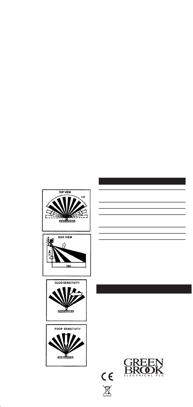
Field of Detection
The field of detection of the infrared
O
lamp can be adjusted 30
O
horizontally.
30
vertically and
The horizontal
O
detection
120
range can be
reduced or
expanded, see
Fig. 4
Fig. 4 & 5, to
reduceany false
detections caused
by movements
from neighbouring
grounds.
The best detection
Fig. 5
is obtained by
approaching the
field of detection
perpendicular
toits axis. See Fig. 6
If the field of
detection is
Fig. 6
approached
in the direction
of its axis, the
infrared detector
will, in some
cases, respond
Fig. 7
later, See Fig 7.
TECHNICAL DATA
Power Source:- 220 - 240V AC 50Hz
Max Lighting
Load: 400W class C Xenon Tube
Detection Angle: 120 dgrees (fan shaped)
Detection Range: 12M (adjustable)
Time Delay: From 9 secs to 10 mins
(adjustable)
Light Sensitivity: 30 Lux (adjustable)
Power cord: H05RN-F 3G 1.0mm
Glass: 177 x 140 x 5mm
2
GUARANTEE
Your KingShield Xenon Floodlight with PIR is
guaranteed for 12 months from
the date of purchase.
This does not affect your statutory rights.
Please keep these instructions for future reference.
INSTALLER - Please pass instruction manual
onto the owner of the unit
Issue no: 703174
WEST ROAD . HARLOW
ESSEX . CM20 2BG . UK
sales@greenbrook.co.uk
W W W. GR EEN B R O O K . CO .U K
 Loading...