

King Pigeon RTU5012 User Manual

GSM SMS Alarm & Dialer
-- Ultra Version!
Inquiry Onsite AC
Power Status with a
SMS!
Cost-Effective GSM
Dialer Solution In
The Worldwide!
User Manual
RTU5012
Ver 1.1
Date Issued: 2013-11-12
All rights reserved by King
Pigeon Hi-Tech.Co.,Ltd.
www.GSM-M2M.com
GSM SMS Voice Alarm Dialer
GSM Power Monitoring Alarm
Page 2 of 20 Ver 1.1
GSM SMS Voice Alarm Dialer
GSM Power Monitoring Alarm
Warming Tips---Quickly Guide
If you need the AC power monitoring function only, please read the chapter 5.7~ 5.8, 6.2, 6.14, 6.16 and chapter 7.3 to get
the quickly settings to save you time. After you setup, please remove the RTU5012 AC/DC Adaptor to check if you can get
SMS alert according to the 6.16 preset time.
Index
SMS Command List
SMS COMMAND
Functions & Actions
AA
To arm the GSM Dialer, in this mode, any detector triggered will alarm.
BB
To disarm the GSM Dialer, in this mode, detector triggered will not alarm.
CC
To switch on the siren.(The function available after 2014-03-15)
DD
To switch off the siren. (The function available after 2014-03-15)
EE
Inquiry the RTU5012 Status and GSM Module IMEI Code.
*The commands should plus Password, the format is Password+SMS Command. i.e.: if the password is 1234, then
you can send 1234AA to arm, 1234BB to disarm, the AA~EE must be Caps Lock.
This handbook has been designed as a guide to the installation and operation of GSM Dialer and GSM Power
Monitoring Alarm.
Statements contained in the handbook are general guidelines only and in no way are designed to supersede the
instructions contained with other products.
We recommend that the advice of a registered electrician be sought before any Installation work commences.
The manufacturer, its employees and distributors, accept no liability for any loss or damage including consequential
damage due to reliance on any material contained in this handbook.
The manufacturer, its employees and distributors, accept no liability for GSM Network upgrading or SIMCard
upgrading due to the technology specifications contained in this handbook.
1.Brief introduction --------------------------------------3
2.Safety Directions --------------------------------------3
3.Standard Packing list ---------------------------------4
4.Mainly Features ----------------------------------------4
5.Installation and Connection Diagram -----------5
5.1 Inserting the SIMCard -----------------------------5
5.2 Making the Outlets for wires-------------------6
5.3Contacting the Wired Sensor,CCTV,IP Camera
or Other Alarm Panel to the GSM Dialer ------6
5.4Contacting the Siren, hooter -------------------8
5.5Contacting the Backup Battery ---------------8
5.6Contacting the External GSM Antenna ------9
5.7Contacting the AC/DC Power Supply---------9
5.8Switching on/off the GSM Dialer-------------10
5.9Amounting the GSM Dialer-------------------10
5.10Reset to Factory Default ----------------------10
6.Settings--------------------------------------------------10
6.1Setup New Password-----------------------------12
6.2Setup Authorized number----------------------12
6.3Inquiry the Authorized number-----------------13
6.4Remove the Authorized Number--------------13
6.5Modify the wired zone type----------------------13
6.6Modify the SMS Alarm Content---------------13
6.7Inquiry the SMS Alarm Content Setting------13
6.8Setup the Zone Attribute -------------------------------14
6.9Setup the Siren Sound time--------------------------14
6.10Setup the Alarm Delay Time--------------------------14
6.11Setup the Arm Delay Time----------------------------15
6.12Enable to Alert the first Authorized Number ---15
6.13Required the GSM Dialer callback------------------15
6.14Setup External Power Status Alert Feature-------15
6.15Setup Siren Response Feature ---------------------16
6.16Setup Automatically report Status function--------16
7.Operating Instructions --------------------------------------16
7.1Armed or Stay WITH a FREE call --------------------16
7.2SMS Commands for Arm or Disarm or Switch
On/Off Siren. ----------------------------------------------17
7.3Inquiry Status and GSM Module IMEI Code--------17
7.4iOS App and Android Apps Instructions--------------18
8.Technical specifications-------------------------------------18
9. Maintenance----------------------------------------------------18
10.Warranty --------------------------------------------------------19
11.Affix Table------------------------------------------------------19
Table 1. GSM Dialer Installation Schedule---------------19
Table 2. GSM Dialer SMS Command List-----------------19
Page 3 of 20 Ver 1.1
GSM SMS Voice Alarm Dialer
GSM Power Monitoring Alarm
1. Brief introduction
The GSM Dialer is an Ultra Version of GSM Alarm, includes multi-functions and ultra low cost and high
reliability special for Residential areas, business area, commercial area, office, factory, industrial area and
other Varity applications. It integrated high performance GSM Module and MCU inside, and with innovative
and experienced functions and features to meet the required and potential demands in the worldwide
markets.
The user can receive SMS Text and calling from the GSM Dialer once the alarm occurrence immediately.
Also, remotely switch the GSM Dialer to arm or disarm with free call from mobile phone, or remotely call in
the GSM Dialer to listen in on-site, or send SMS Command to request the GSM Dialer call back.
The GSM Dialer equips 1 wired inputs for IP Camera Alarm Output, other alarm panel output to transfer
alarm message by SMS over GSM Network.
The GSM Dialer inbuilt power detection circuit, no need any other detector or sensor to monitoring the
external power directly. Once external power goes off or goes on, the GSM Dialer can send SMS or dial
upto 6 authorized mobile phones.
2.Safety Directions
Safe Startup
Do not use GSM Dialer when using GSM equipment is prohibited or might bring disturbance
or danger.
Interference
All wireless equipment might interfere network signals of GSM Dialer and influence its
performance.
Avoid Use at Gas Station
Do not use GSM Dialer at a gas station. Power off GSM Dialer when it near fuels or
chemicals.
Power it off near Blasting Places
Please follow relevant restrictive regulations. Avoid using the device in blasting places.
Reasonable Use
Please install the product at suitable places as described in the product documentation. Avoid
signal shielded by covering the mainframe.

Page 4 of 20 Ver 1.1
GSM SMS Voice Alarm Dialer
GSM Power Monitoring Alarm
Use Qualified Maintenance Service
Maintenance can be carried out only by qualified maintainer.
3. Standard Packing List
GSM DialerX1
User Manual X1
Optional Accessories: (Wired detectors)
PIR Motion Sensor, Glass Break Sensor, Magnetic Window Sensor, Temperature Sensor, Infrared Beam
Fence, Vibration sensor, AC power status detectors.
4. Mainly Features
Supports Away Armed, Partial Armed(At House or Stay) or Disarmed by SMS Commands, Call in with
free charge;
Supports 6 Authorized Numbers, each number can be setup as receive SMS or receive call or both of
them, also, each number can be setup authorized to call in to arm or stay the system;
Automatically send SMS Alert Alarm Message and dial to the authorized numbers when alarm
occurrence;
Supports 1 wired zones(Dry Contact Type), the input can be Normal Close(NC), Normal Open(NO),
special for IP Camera alarm output or other wired sensor connection;
Supports verity programmable zone attributes, includes Away(normal), At House or Stay, Entrance
Zone, 24 Hours Sound Zone, 24 Hours Silent Zone, Local Zone, SOS Zone, Door Bell Zone;
The SMS Alarm Content of the digital input is programmable by user through SMS Commands;
Supports Armed delay to give enough time to leave the home, the delay time is programmable by user;
Supports Alarm Delay to give enough time to Disarm it when you come back home, the delay time is
programmable by user;
Equips one siren output for sounding while alarm occurrence to warning;
Equips one Microphone inside, the authorized number can call in to listen onsite or request it call back.
The external AC power failure & recovery alert function supports 2 optional: Immediately Send SMS to
user, after 30 minutes if not recovery then send SMS to user;
Page 5 of 20 Ver 1.1
GSM SMS Voice Alarm Dialer
GSM Power Monitoring Alarm
Standby internal large capacity rechargeable battery which can standby upto 8hours after AC Power
failure, also can provide power to wired siren after AC power failure;
Secure - Using caller ID for identification, unknown callers are ignored;
Supports Password to increase the security of the whole system;
Based on the GSM communication network, no distance limitation.
5. Installation and Connection Diagram
Tips:
a. The backup battery was disconnected, please contact it firstly according to 5.6.
b. After switched on the GSM Dialer, will indicate by a long Di sound,all zones’ LED will turn on once, and
the zones which registered wireless sensors, wireless remote control or wireless buttons will turn on once
more.
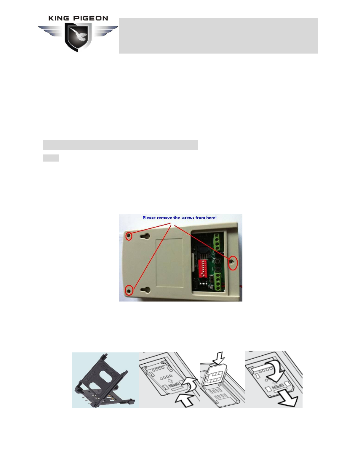
In the backside of the GSM Dialer, please remove all of the 3 screws, and take the back cover off,
then you can see the PCB. See below:
5.1 Inserting the SIMCard
Important: Make sure to switch off GSM Dialer before inserting or removing your SIM card.
1) Slide the SIM card holder in the direction of “OPEN” (etched on the SIM card holder), and then flip
it open.
2) Insert the SIM card with its gold contacts facing down and its cut-off corner facing out the SIM card
slot. See above photo.
Page 6 of 20 Ver 1.1
GSM SMS Voice Alarm Dialer
GSM Power Monitoring Alarm
3) Slide the SIM card completely into the slot. Make sure the SIM card goes through the 2 “guides” on
the SIM card slot.
4) Close the SIM card holder and then slide it in the opposite direction of “OPEN” to lock it. See
above photo.
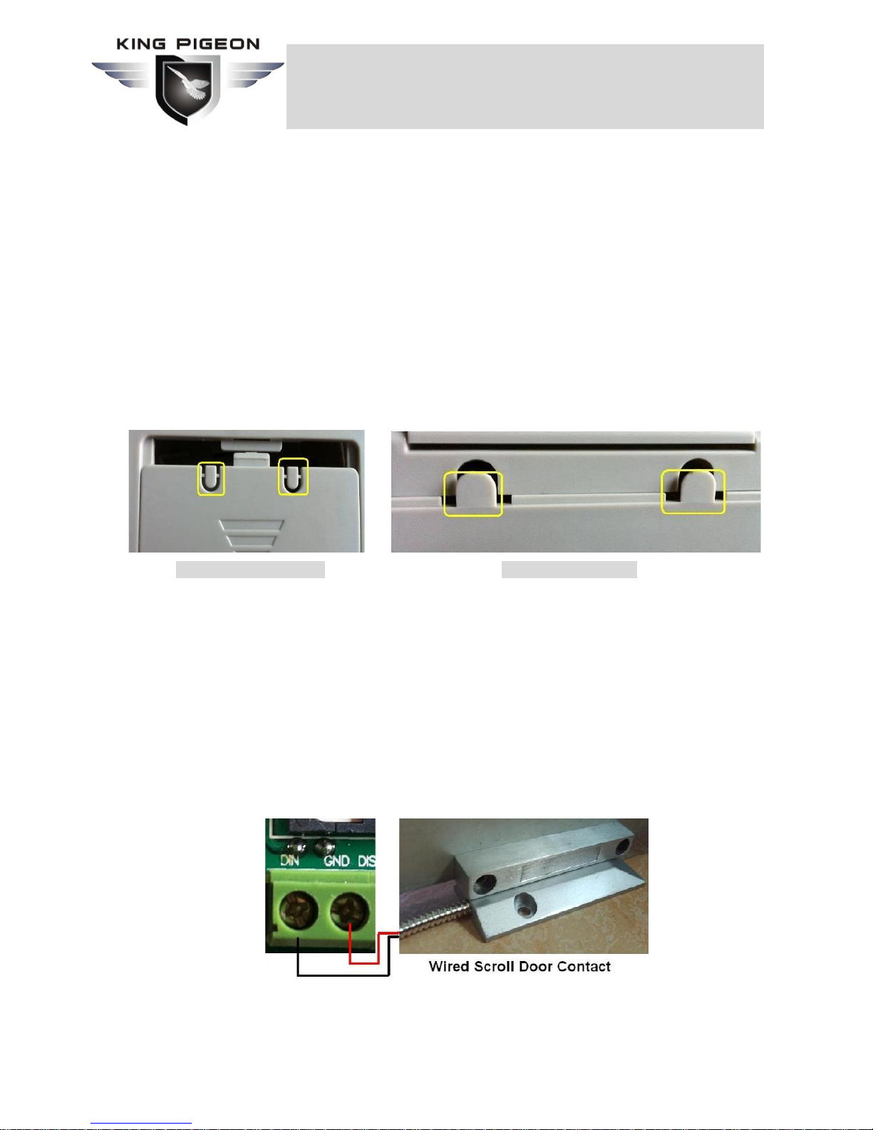
5.2 Making the Outlets for wires
The GSM Dialer reserved 4 outlets for wires at backside outlets and bottom outlets. The user can
choose the suitable one for different installation requirements. Please use a knife or other tool to
remove the obstacle plastics. Usually, the siren and power supply wires were in one outlets, and the
signal control wires in another outlet to avoid the interference.
Backside Wires Outlet Bottom Wires Outlet
5.3 Contacting the Wired Sensor or IP Camera or Other Alarm Panel to the GSM Dialer
The GSM Dialer equips one dry contact (Normal Close or Normal Open type) digital input port, the
user can connect the IP Camera or CCTV DVR or wired detector or other alarm panel to this port.
When the digital input triggered by IP Camera or CCTV DVR or wired detectors or other alarm panel, it
will alarm.
1) Contacting the wired Detector to GSM Dialer
The wired detector has two connectors, please contact one of them to the DIN port, another
contact to the GND port. And setup the Digital input be the correct NC or NO type by SMS
Commands. (Tips: if you don’t know the NC or NO type of the Detector, please try to change the
setting to NC or NO type by SMS Commands to after you finished connections.)
If you need to contact more than one wired to the GSM Dialer, please ensure all of the wired
detectors are the same output type (Normal Close or Normal Open Types), any one of these
detectors triggered, the GSM Dialer will alarm.
 Loading...