

Page 1

Mapping Registers for
extending I/O or Instrument
Max. 10MHz High Speed Pulse
Counter
Max. 300KHz High Speed
Pulse Output
MxxT Series
User Manual
Ver 2.0
Date Issued: 2019-11-28
King Pigeon Hi-Tech. Co., Ltd.
www.IOT-Solution.com
Industrial
Ethernet Remote I/O Module
Page 2

Industrial Ethernet Remote I/O Module
IoT Data Acquisition Module
Modbus TCP Ethernet Remote I/O Module Model List
Model
Descriptions
DC Output
DC Input
Typical Power
Consumption
M100T
1 RJ45,1 RS485, 2 DI, 2 AI, 2 DO
1 DC
9~36VDC
160mA@12V
M110T
1 RJ45,1 RS485, 4 DI, 4 DO
1 DC
M120T
1 RJ45,1 RS485, 4 DI, 4 AI, 2AO(0-10V), 4 DO
1 DC
24~36VDC
90mA@24V
M130T
1 RJ45,1 RS485, 8 DI, 4 DO
1 DC
9~36VDC
150mA@12V
M140T
1 RJ45,1 RS485, 8 DI, 8 DO
1 DC
M150T
1 RJ45,1 RS485, 8 DI, 4 AI, 4 DO
1 DC
M160T
1 RJ45,1 RS485, 8 DI, 48 AI, 8 DO
1 DC
M200T
1 RJ45,1 RS485, 2AO(0-10V)
1 DC
24~36VDC
90mA@24V
M210T
1 RJ45,1 RS485, 4 DI
1 DC
9~36VDC
160mA@12V
M220T
1 RJ45,1 RS485, 4 DO
1 DC
160mA@12V
M230T
1 RJ45,1 RS485, 4 AI
1 DC
160mA@12V
M240T
1 RJ45,1 RS485, 4 RTD, 2/3 wire PT100/PT1000
1 DC
100mA@12V
M310T
1 RJ45,1 RS485, 8 DI
1 DC
150mA@12V
M320T
1 RJ45,1 RS485, 8 DO
1 DC
M330T
1 RJ45,1 RS485, 8 AI
1 DC
M340T
1 RJ45,1 RS485, 8 RTD, 2/3 wire PT100/PT1000
1 DC
100mA@12V
M410T
1 RJ45,1 RS485, 16 DI
1 DC
160mA@12V
M420T
1 RJ45,1 RS485, 16 DO
1 DC
110mA@12V
Special instructions for ordering:
1) If the model provides digital input, the DIN default type: wet contact, optional: dry contact. The input type
cannot be changed after manufacturer delivered. The DIN1 default is high-speed count mode; it can be
changed to low-speed count mode by open the shell and change the internal jumper. If require dry contact
input, please note when ordering, if DIN1 require high-speed pulse count mode then must be wet contact.
2) If the model provides digital output, the DO type is SINK, DO1 supports high-speed pulse output; DO2 can be
used to control the direction of the stepper motor. Also can connect external relay if need.
3) The model number: M240T, M340T support thermal resistance temperature transmitter default type: PT100,
optional: PT1000, if you need PT1000 type of thermal resistance, please note when ordering.
4) All models support the register mapping, can extend I/O or meters via Modbus RTU protocol.
5) Each model’s I/O port qty is referred to the above table only. As MXXT series use same housing, those I/O
port hardware terminal blocks on the device which not described in the table is not valid.
Page2of
25
King Pigeon Hi-Tech. Co., Ltd. Ver 2.0
Page 3

Industrial Ethernet Remote I/O Module
IoT Data Acquisition Module
Table of Contents
DATE
FIRMWARE VERSION
HARDWARE VERSION
DESCRIPTION
2017-04-17
V1.0
2019-11-18
V2.0
New version
This user manual has been designed as a guide to the installation and operation of MxxT Series Ethernet Remote I/O
Module.
Statements contained in the manual are general guidelines only and in no way are designed to supersede the
instructions contained with other products.
We recommend the advice of a registered electrician before any Installation work.
King Pigeon Hi-Tech.Co., Ltd, its employees and distributors, accept no liability for any loss or damage including
consequential damage due to reliance on any material contained in this manual.
King Pigeon Hi-Tech.Co., Ltd, its employees and distributors, accept no liability for any Network upgrading or due to
the technology specifications contained in this manual.
【UPGRADE HISTORY】...................................................................................................................................................3
1. Brief introduction......................................................................................................................................................... 4
2.Standard Packing List.....................................................................................................................................................5
3. Mainly Features............................................................................................................................................................5
4. Technical Specifications................................................................................................................................................6
5. Physical Layout and Installation Diagram.................................................................................................................... 9
5.1 Physical layout.................................................................................................................................................9
5.2 Led Instruction...............................................................................................................................................10
5.3 Interface Instructions for installation............................................................................................................10
5.4 Typically Wiring Instruction:..........................................................................................................................11
5.5 Setup the DIN1 High Speed Pulse Count & Low Speed Pulse Count Mode:................................................. 12
6. Initialize/Reset the Module........................................................................................................................................12
7. Settings&Operation....................................................................................................................................................12
7.1 Ready to set up:.............................................................................................................................................12
7.2 Selection Description.....................................................................................................................................13
7.3 Basic Setting..................................................................................................................................................14
7.4 Network Settings...........................................................................................................................................15
7.5 Slave Settings................................................................................................................................................ 16
7.6 Register list....................................................................................................................................................18
7.7 System Log.....................................................................................................................................................19
8. Modbus Protocol........................................................................................................................................................20
8.1 Read Input Coil (Function Code 2: Read Coil)...................................................................................................20
8.2 Read and Write Holding Coil............................................................................................................................ 21
8.3 Read Input Register.......................................................................................................................................... 21
8.4 Read and Write Holding Register.....................................................................................................................23
8.5 Mapping Register----Transit BIT Register Address...........................................................................................24
8.6 Mapping Register----Transit 16-Bit Register Address...................................................................................... 24
9. Warranty.....................................................................................................................................................................24
【UPGRADE HISTORY】
Page3of
25
King Pigeon Hi-Tech. Co., Ltd. Ver 2.0
Page 4

Industrial Ethernet Remote I/O Module
IoT Data Acquisition Module
1. Brief introduction
The MxxxT Ethernet Remote I/O Module is an industrial class, isolated designed, high reliability, high stability and
high precision data acquisition module, embedded 32-Bit High Performance Microprocessor MCU, Integrated 1
Industrial 10/100M adaptive Ethernet module inside. It provides multi I/O, supports standard Modbus TCP,
supports modbus master and slave, can be integrated into SCADA, OPC server, and other automation systems. It is
design for working in the harsh industrial application environment, widely used in a variety of industrial
automation, security monitoring system, automatically measurement and control system.
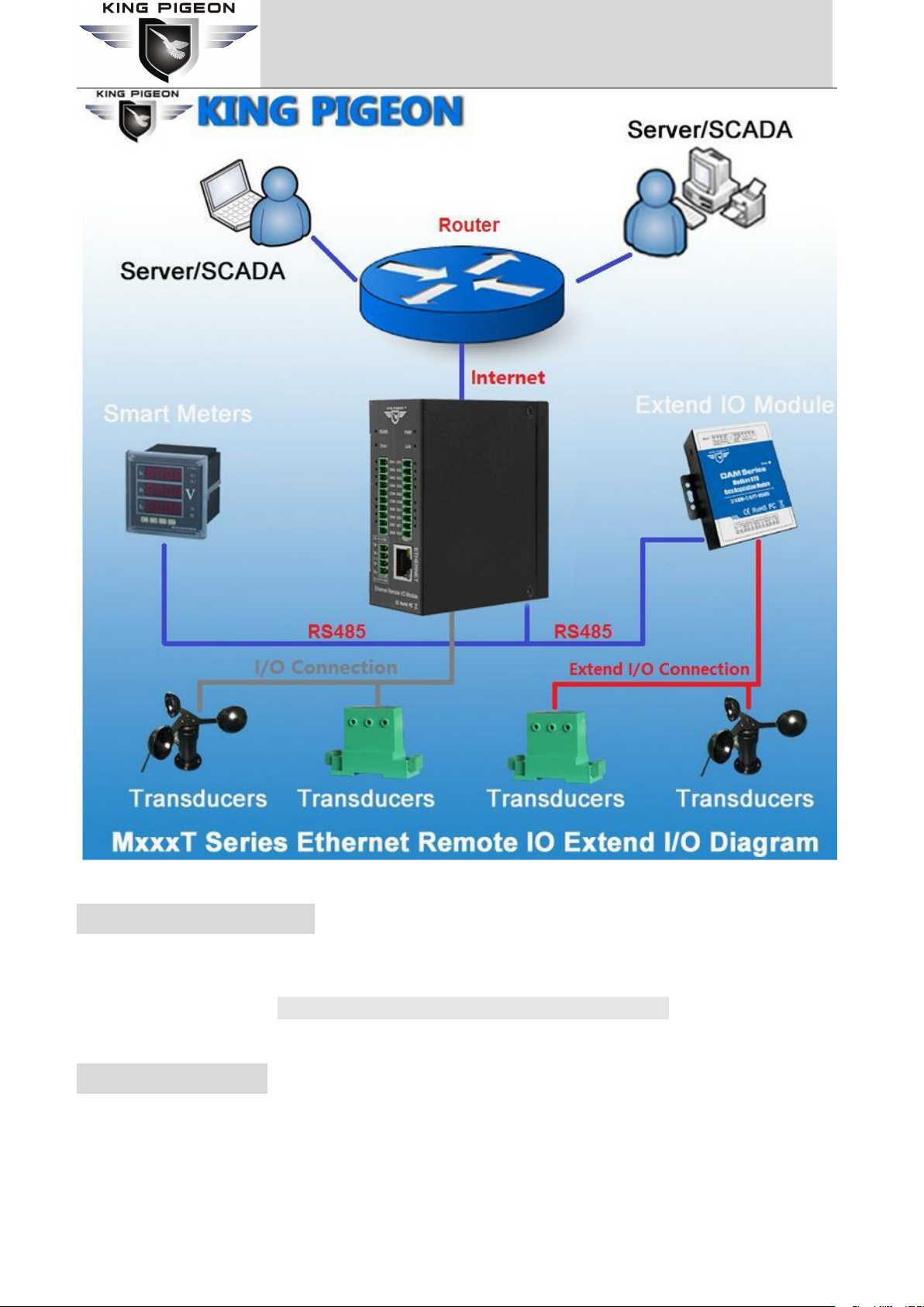
The MxxxT Ethernet Remote I/O module provides a RS485 interface, through the RS485 bus, it can cascade
Modbus I/O devices or Modbus meters, e.g.: a variety of digital input or digital outputs, analog inputs or outputs,
thermal resistance IO module combination, save costs. At the same time, the Ethernet Remote I/O module has
register mapping function, the cascade Modbus I/O data are automatically collected to the register mapping area,
the TCP Client polling without waiting then can get a quick response to meet the industrial timely requirements.
The MxxxT Ethernet Remote I/O module provides different I/O ports for variety applications. Includes
optical-isolated digital inputs, compatibles dry contact and wet contact, supports max 700KHz high speed pulse
counter, digital outputs supports 10Hz~300Khz high speed pulse output or relay outputs, isolated 12bits analog
inputs, supports 0~5V, 0~10V, 4~20mA, 0~20mA analog signal, 12bits analog outputs, supports 0~10VDC signal
output, resistance thermal detector inputs compatibles 2/3 wires PT100 and PT1000. All of the I/O ports are high
sampling frequency and special filtering strategy to ensure its reliability.
The MxxxT Ethernet Remote I/O module can work at wide working voltage range, the range is 12 ~ 36VDC with
anti-reverse protection design. Also, it provides 1channel 12~36VDC power output for external device to save
wiring cost.
Page4of
25
King Pigeon Hi-Tech. Co., Ltd. Ver 2.0
Page 5
Industrial Ethernet Remote I/O Module
IoT Data Acquisition Module
2.Standard Packing List
Ethernet Remote I/O Module X 1, Card type Manual X 1, 35mm Standard DIN rail fixed Bracket*1.
Note: The package does not include AC/DC Adaptor.
3. Mainly Features
Standard Modbus TCP protocol and Modbus RTU over TCP communication protocol;
Embedded 32-Bit High Performance Microprocessor MCU, inbuilt watchdog;
Power supply 12~36VDC with over voltage and phase-reversal protection;
Page5of
25
King Pigeon Hi-Tech. Co., Ltd. Ver 2.0
Page 6

Industrial Ethernet Remote I/O Module
IoT Data Acquisition Module
Management and configuration via LAN connection configuration software for easy operation and
• Digital Input
Type
Wet Contact (NPN or PNP), Dry Contact. Default wet contact, if need dry
contact ,pleases tell us when order
I/O Mode
DI or Pulse Counter
Dry Contact
• On: short to GND, logic=1
• Off: open, logic=0
Wet Contact (DI to COM)
• On: 10 to 30 VDC,logic=1
• Off: 0 to 3 VDC,logic=0
Pulse Counter Frequency
Only the 1stChannel can be used as pulse counter, Compatibles DI and
counter simultaneously. Counter value will save if power off.
High Speed Mode: Max. 700Khz(Default);
Low Speed Mode: Max. 10KHz (Optional, can open the cover to choose
low speed mode.)
Digital sampling frequency
500Hz,3 times ACK
Digital filtering strategy
Support Anti-Shake Mechanism
Isolation
Optical Isolated,3k VDC or 2kVrms
• Digital Output
Type
Sink or pulse or relay(default is sink,can control ≤24V DC ≤0.5A relay
directly ,otherwise must connect external relay)
I/O Mode
Sink or Pulse Output
maintenance;
Integrated 10/100M adaptive Ethernet port, With 15KV ESD protection;
Optical isolated digital input(Compatible Dry or Wet type), supports max 700KHz high speed pulse counter;
DO supports Sink output,DO1 can be used as high-speed pulse output, supports 10Hz~300KHz ;
Isolated analog input, 12-bit resolution, supports 0~20mA,4~20mA,0-5VDC, 0-10VDC;
Analog output, 12-bit resolution, supports 0-10VDC;
RTD input, supports PT100 and PT1000 resistance sensor, compatible 2 or 3 wires;
High sampling frequency and special filtering strategy to ensure reliability;
1 RS485 Serial port, supports Modbus RTU Master/Slave, can extend I/O modules;
Supports register mapping function and extend I/O inquiry strategy;
Provides 1 channel VDC power source output for external device, saving wiring cost;
LED instructions work status, with reset button to reset, easy on-site installation and commissioning;
Using metal shell, protection class IP30. Metal shell and system security isolation, especially suitable for
industrial applications in the field;
Small size, L82 * W40 * H99mm, compatible wall installation and DIN35mm industrial rail installation.
4. Technical Specifications
Page6of
25
King Pigeon Hi-Tech. Co., Ltd. Ver 2.0
Page 7

Industrial Ethernet Remote I/O Module
IoT Data Acquisition Module
Pulse Output Frequency
10Hz~300KHz(Only the 1stChannel is Sink type can be used as high speed
pulse output)
Over-Voltage Protection
50V DC
Over-Temperature Shutdown
175°C (typical), 150°C (min.)
Load Current
Max.500 mA per channel
Digital sampling frequency
500Hz
Isolation
If DO is Sink type, then no isolation. If it is Relay, then is electrical
isolation.
• Analog Input
Type
mA/V
Resolution
12 bits
Current-type input impedance
124Ohm
Input Range
0~5VDC , 0~10VDC, 0~20 mA, 4~20mA,
Accuracy
±0.1% FSR @ 25°C
±0.3% FSR @ -10 and 60°C
Sampling frequency
20Hz
Isolation
Electrical isolation
• RTD Input
Sensor Type
PT100 or PT1000(default PT100,If need PT1000,please tell us when order)
Measurement Range
-50 ~ +300℃
Resolution
0.1°C or 0.1 ohm
Input Connection
2 or 3-wire
Accuracy
±0.1% FSR @ 25°C
±0.3% FSR @ -10 and 60°C
Sampling frequency
20Hz
Isolation
No
• Analog Output
Type
0-10V DC
Resolution
12 bits
Output Range
0 to 10 VDC
Load Current
1A (max.)
Accuracy
±0.1% FSR @ 25°C
±0.3% FSR @ -10 and 60°C
Isolation
No
• Working Power Requirements
Page7of
25
King Pigeon Hi-Tech. Co., Ltd. Ver 2.0
Page 8

Industrial Ethernet Remote I/O Module
IoT Data Acquisition Module
Input Voltage
9~36VDC for no-AO output model,
24~36VDC for AO output model;
Peak Voltage:+40VDC, Power consumption: Less than 2W,
• LAN
Ethernet
10/100 Mbps adaptive Ethernet module, RJ45 ports
Protection
15KV ESD Protection
Protocols
Modbus TCP Master or Slave, TCP/IP
TCP Connection
Can be TCP client and server. As TCP server, support max 5 TCP client
connection
• Serial Port
RS485
MODBUS RTU Master or Slave.
Protection
15KV ESD Protection
Modbus Slave address
1~247
Polling Frequency
Default is 50mS,range:30-65535mS
Baud Rate
2400,4800,9600,19200,38400,57600,115200,128000Bps;
Mapping registers
Bit registers: 300, 16-Bit register: 300. Total 600 mapping registers.
• Physical Characteristics
Wiring
I/O cable max. 14 AWG
Dimensions
82x 40 x 99 mm
Weight
300 g
Mounting
DIN rail or wall-mounted
• Environmental Limits
Operating Temperature
Standard Models: -20 to 70°C (-4 to 158°F)
Storage Temperature
-40 to 85°C (-40 to 185°F)
Ambient Relative Humidity
5 to 95% (non-condensing)
Page8of
25
King Pigeon Hi-Tech. Co., Ltd. Ver 2.0
Page 9

Industrial Ethernet Remote I/O Module
IoT Data Acquisition Module
5. Physical Layout and Installation Diagram
5.1 Physical layout
35mm Standard DIN rail fixed Bracket:
Page9of
25
King Pigeon Hi-Tech. Co., Ltd. Ver 2.0
Page 10

Industrial Ethernet Remote I/O Module
IoT Data Acquisition Module
5.2 Led Instruction
LED Indicator Instruction
Power Indicator: Power on the device,PWR will always on.
Link Indicator: MODBUS TCP connection successful will always on.
RS485 Indicator: Flicks while receiving data on RS485 Serial port.
RS485 Indicator: Flicks while sending data on RS485 Serial port.
Digital input status indicator, turn on or input high level, or will close.
Digital Output status indicator, turn on or output high level, or will close.
Interface Definition Instruction
DC in 9~36V
+
DC9~36V positive input, 1A, for power on the Unit. If need to use the AO port,
then please power on it by DC24~36v.
–
DC12~36V negative input.
DC Out 9~36V
+
DC Power output positive for external device, output voltage= input voltage.
5.3 Interface Instructions for installation
See below interface definition, please connect the correct wires.
Page10of
25
King Pigeon Hi-Tech. Co., Ltd. Ver 2.0
Page 11

Industrial Ethernet Remote I/O Module
IoT Data Acquisition Module
GND
DC Power output negative external device, output voltage= input voltage
Reset
Reset button. Recovery the parameters to factory default value.
ETHERNET
Ethernet port.
RS485
A
RS485 data A
B
RS485 data B
GND
RS485 data ground if required.
Digital Input
DINx+
The x channel digital input positive
GND
Digital input negative
Digital Output
DOx+
The x channel Digital Output High Level or Relay NO port.
GND
Sink output: GND (For output type is SINK.)
COM
Relay output: COM.(For output type is Relay)
Analog Input
AINx+
The x channel Analog input positive.
GND
Analog input negative.
Analog Output
AOx+
The x channel Analog output positive.
GND
Analog output negative.
RTD Input
RTDx+
The x channel Resistance Thermal input positive.
RTDx -
Resistance Thermal input negative.
COM
Resistance Thermal input COM port.
5.4 Typically Wiring Instruction:
Tips:
Resistance Thermal Detector (RTD) compatibles 2-wire or 3-wire, please reference abovementioned wiring instruction. If
the sensor near the module and the wire resistance is small can be ignored, can be used 2-wire wiring, if the distance is far
and the wire resistance affect the value, should be used 3-wire way connection.
Page11of
25
King Pigeon Hi-Tech. Co., Ltd. Ver 2.0
Page 12

Industrial Ethernet Remote I/O Module
IoT Data Acquisition Module
5.5 Setup the DIN1 High Speed Pulse Count & Low Speed Pulse Count Mode:
High speed mode:
Short-circuit the upside 2 pins of
JP2&JP3’s with Caps.
Low speed mode:
Short-circuit the downside 2 pins
of
JP2&JP3’s with Caps.
The DIN1 can be used as pulse counter, default is high speed mode, the max. Frequency is 700Khz. it can be change
to low speed pulse count mode by open the shell, and change the JP2&JP3’s jump Caps to the right side2PINs, see
below pictures.
6. Initialize/Reset the Module
The device can be reset to factory default if mistake programmed. Please follow below steps to initialize it. After
initialized, the parameters will set as factory default.
1) Switch off the device
2) Press and hold the RESET button;
3) Power ON the Unit, waiting for 3 seconds, all the 4 lights( PWR, Link, RS485, Error Led Indicators) will turn on,
then loose the RESET Button, the other lights will flick for 5 times then turn off, while the PWR Led indicator
keeps on.
4) Turn off and Restart the device then recovery to factory default settings, and will enter to work mode. All of
the parameters will be reset to factory default.
7. Settings&Operation
The MxxT Ethernet Remote I/O module provides a standard Ethernet RJ45 interface, through the direct line
connect to the router, switches, HUB and other interconnect switching equipment, or through the cross-line
connect to PC and other terminal devices. The user can program parameters, firmware upgrades and debugging
through the WEB configuration interface. In the actual use, the Master will communicate it by MODBUS to read
and write the local register address and mapped registers of the slave I / O.
Below are the steps to setup the parameters by software, please follow it step by step.
7.1 Ready to set up:
1) Through the direct line connect to the router, switches, HUB and other interconnect switching equipment, or
through the crossover cable connect to PC and other terminal devices, And make sure the device and computer are
Page12of
25
King Pigeon Hi-Tech. Co., Ltd. Ver 2.0
Page 13

Industrial Ethernet Remote I/O Module
IoT Data Acquisition Module
in the same LAN.
2) Powered on the device, the PWR LED indicator will turn on and the device will initialize within several second.
3) At the PC, open the software, click “search device”, Double click the device you find and enter password(default
is 1234). After password verification, you can set parameters.
Tips:
* If the first connection is through a crossover cable to the PC, the device IP will be 192.168.1.110. You need to change the
computer IP to 192.168.1. * to find the device..
7.2 Selection Description
System Settings
[Login Password]: Parameter setting can be done after login. The default password is 1234.
[Change Password]: Modify the device password. After modification, you need to log in with the new password.
[Save Data]: Save the parameter configuration to the device.
[Loading Data]: Read the parameter configuration of the device. Please read the current configuration before
setting the parameters.
[Restart]: Click this item to restart the device.
[Close]: Click this item to close the configuration software.
Device Search
[Login Password]: Click this item to search device.
File Operation
[Load File]: Import the previously exported configuration file parameter information to the configuration
Page13of
25
King Pigeon Hi-Tech. Co., Ltd. Ver 2.0
Page 14

Industrial Ethernet Remote I/O Module
IoT Data Acquisition Module
software.
[Save File]: Export the current parameter information on the configuration software to a computer configuration
file,convenient for next configuration.
Language Selection
[Chinese]: Click to switch language to Chinese.
[English]: Click to switch language to English.
7.3 Basic Setting
Device ID: Default is 1, can be 1~247.
Device Information: Max 32 characters,this is the description of the module, e.g.: installation address, usage
instructions and so on.
AIN Setting: 0~5V,0~10V,0~20mA,4~20mA are optional,After selecting the specific mode, you also need to set the
AIN switch to the corresponding position on the hardware; [Maximum value] and [Minimum value] are
the sensor range, and [Current value] will be automatically converted to the real value according to the
set range.
DIN Input Status: :The state of the digital input. When the state of the digital input is closed, the corresponding
value in the list is 1, otherwise it is 0.
DIN1 Counter Default Trigger Direction: Can be set as rising edge or falling edge, need restart to take effect
DO Output Status: The Digital output status,When the status of the digital output is closed, the corresponding,
value in the list is 1, otherwise it is 0.
Double-click the value of a specific DO to change it, and the corresponding DO will immediately
output related actions;
Click [Turn On] or [Turn Off], all DO will output related actions immediately.
DO1 Pulse Output ,DO2 Direction Control: :Tick”Enable”,stands for DO1 is used as pulse output and DO2 is used as
direction control after the device restarts.
Page14of
25
King Pigeon Hi-Tech. Co., Ltd. Ver 2.0
Page 15

Industrial Ethernet Remote I/O Module
IoT Data Acquisition Module
PT100/PT1000 Temperature Value: :It is the corresponding thermal resistance PT100 / 1000 channel converted
temperature value.
AO Output Test: :[AO1], [AO2] correspond to AO1 and AO2 channels. Adjust the DAC value of AO output by sliding
the slider. The output values of AO1 and AO2 cannot preset. In actual use, it is set by the host computer, 12-bit
accuracy,range is 0 ~ 4095, corresponding to the output voltage 0 ~ 10VDC, and the maximum load is 1A.
Note: After setting, please click "System Settings"-"Loading data" option to save the set parameters.
7.4 Network Settings
Got the IP address Auto: Tick it stands for: the device automatically obtains the IP address in the LAN. Only when
the router in the LAN allows the dynamic allocation of IP addresses can be used.
User Specifies the IP Address: Tick it stands for the user setup a fixed IP address for the module.
IP Address,Gateway,Netmask,Primary DNS,Secondary DNS: Only can be set After choose”User specifies the IP
address”.
Modbus TCP listening port: 1~65535,default is 502,listen TCP Client establish connection port,supports max 5 TCP
Client connection.
Modbus over TCP Active Connection Settings:Tick it stands for device will connect to the server automatically ,or
will not connect.
Server 1/2 IP/Domain,Server 1/2 Port: The device will connect to server 1 first, and connect to server 2 when the
connection fails.
Register Packets: Registration packet sent by the device to the server when connecting to the server.
Register ACK Packets: If this option is set, when registering to connect to the server, the server must deliver the
Page15of
25
King Pigeon Hi-Tech. Co., Ltd. Ver 2.0
Page 16

Industrial Ethernet Remote I/O Module
IoT Data Acquisition Module
corresponding data to the device, otherwise the device considers the registration connection failed.
Heartbeat Packets: Heartbeat content to avoid network offline
Heartbeat ACK Packets: Once set,When receiving the heartbeat packet, the server must send the corresponding
data to the device. If the device does not receive this data for 3 consecutive times, it will
disconnect.
Disconnect Packets: The device will actively disconnect when receiving this data from the server.
Server Strategy: Can choose” Send once when login server,Plus it in front of every packet,Both of them”.
Heartbeat time: 1~9999 seconds,default is 60s.
Re transmission times: 1~9,default is 3.stands for when the device sends data to the server, the server does not
respond and will send it repeatedly 3 times.
Connection time: 1~999,default is 180s.
TCP Slave Setting: TCP client/slave IP,slave port.supports max 5 slaves.
Note: After setting, please click "System Settings"-"Loading data" option to save the set parameters.
7.5 Slave Settings
This series of products provide a serial port and network port to make it have powerful expansion functions. In the
device's internal storage area, 300 BIT-bit registers(Boolean) and 300 16-bit register mapping areas are provided.
(those 300 register can be 16-bit,32-bit or 64-bit,32-bit takes 2 16-bit address,64-bit takes 4 16-bit address
etc).This storage area is used to store slave data, which can reduce the communication response waiting time of
the entire network device and improve communication efficiency.
,
Page16of
25
King Pigeon Hi-Tech. Co., Ltd. Ver 2.0
Page 17

Industrial Ethernet Remote I/O Module
IoT Data Acquisition Module
RS485 Settings
If the slave is only provides RS-232 interface, please use the RS-232/RS-485 converter connected to the 485
network. It is strongly recommended to use the isolated RS485 converter to improve system reliability. In a BUS, all
of the equipments ‘data A + should be connected together, and data B- should be connected together, cannot be
reversed, RS485 signal to the GND terminal should be shorted together, and connect to the module’s ground only.
RS-485 network generally allows up to 32 nodes in parallel devices, more than 32 systems need to use RS485
repeater to expand. RS-485 communication line should be STP(shielded twisted pair), the shield should be
single-ended ground; RS485 communication distance can be up to 1200 meters, when a bus connected to a lot of
RS485 devices, or use high baud rate higher communication distance Will be correspondingly shortened
accordingly, then you can use RS485 repeater to expand. RS-485 network has a variety of topology, the general use
of linear connection, that is, start from near to far, connecting devices to the master one by one. In the far end can
be connected to 120 ~ 300Ω / 0.25 watts of terminal matching resistance (depending on the communication
quality to determine).
Mode Selection : Master or Slave optional.
Baud rate : 2400,4800,9600,14400,19200,38400,57600,115200,128000 optional.
Data Bit: 7,8 bit.
Parity Bit: None, Even and Odd optional.
Stop Bit: 0.5Bit,1Bit,1.5Bit,2Bit optional.
Over time: Wait for the command reply time, the next command will be sent after timeout, default 200ms
Interval: Polling time, each command sending interval time, default is 50ms, please increase the time
appropriately when there are too many slaves.
Retry counts: command reply timeout retry times, default is 3 times.
Mapping Registers--Read Coil & Registers: Mapping registers between the slaves and module
After configuration, the module will Read the Modbus slaves automatically by the corresponding read coil and
register function codes according to the mapped registers.
Slave address : slave device ID,range 1~247.
Function code : Sets the type of action host to slave.Including 02 read input coil, 01 read hold coil, 04 read input
register, 03 read hold register,the values of the input coil and holding coil are automatically
allocated to the mapping storage area of the relay bit register, and the values of the input
register and holding register are automatically allocated to the mapping storage area of the relay
16 bit register.
Slave Start addr : The starting register address for slave data reading.
Number of registers : How many register need to read.
Mapped Addr(100-399) : Stand for mapping the slave start register data to the device start mapping address,
Can be set 100-399,The mapping addresses of the transit Bit and 16-bit registers are
separate, each occupying 300. The mapping addresses of the same type must not be the
same, and the mapping addresses for reading and writing cannot be the same.
Collection Target : Optional RS485, ports 1 ~ 5, corresponding to TCP slaves 1 ~ 5 respectively.
Add : After editing a slave information, click” Add” to map the register address of the cluster device to the
mapping storage area of this device.
Del : Select an edited slave information, click this item to delete the corresponding slave information.
Mapping Registers--Write Coil & Registers: Mapping registers between the slave and module
After configuration, the module will write the Modbus slaves automatically by the corresponding Function codes
according to the mapped registers.
Slave address : slave device ID,range 1~247.
Page17of
25
King Pigeon Hi-Tech. Co., Ltd. Ver 2.0
Page 18

Industrial Ethernet Remote I/O Module
IoT Data Acquisition Module
Function code : Sets the type of action host to slave.including 05/15 write holding coil and 06/16 write holding
register, where the value of the holding coil is automatically allocated to the mapping storage area
of the relay bit register, and the value of the holding register is automatically allocated In the
mapped memory area of the transit 16-bit register.
Slave Start addr : The starting register address for slave data writing.
Number of registers : How many register need to write.
Mapped Addr(100-399) : Stand for mapping the slave start register data to the device start mapping address,
Can be set 100-399,The mapping addresses of the transit Bit and 16-bit registers are
separate, each occupying 300. The mapping addresses of the same type must not be the
same, and the mapping addresses for reading and writing cannot be the same.
Collection Target : Optional RS485, ports 1 ~ 5, corresponding to TCP slaves 1 ~ 5 respectively.
Add : After editing a slave information, click” Add” to map the register address of the cluster device to the
mapping storage area of this device.
Note: After setting, please click "System Settings"-"Loading data" option to save the set parameters.
7.6 Register list
The mapped register list in the Web page is only readable and cannot be written. It is used to display the current
value of the register in the mapping area, which is convenient for user debugging. There are 300 registers for the
Bit Type register, used to store one bit can represent the state of the data, e.g.: input coil, holding coil value. 300
registers for the 16-bit type register, used to store input register and holding register data. 300 BIT-bit
registers(Boolean) and 300 16-bit register mapping areas are provided. (those 300 register can be 16-bit,32-bit or
64-bit,32-bit takes 2 16-bit address,64-bit takes 4 16-bit address)The module will automatically assign and stored
them according to the coil or register set in Mapping Registers page.
Page18of
25
King Pigeon Hi-Tech. Co., Ltd. Ver 2.0
Page 19

Industrial Ethernet Remote I/O Module
IoT Data Acquisition Module
7.7 System Log
This device supports the system log function, which is convenient for users to analyze the operation of the device.
The Record types includes below:
Normal power on, nth boot.
Caused by hardware failure,nth boot
Caused by memory failure,nth boot
Caused by CPU bus failure ,nth boot
Caused by command failure ,nth boot
Factory data restart ,nth boot
Server mode connection request, allow connection
Server mode connection request, exceeding the number of connections, forbidden to connect
Server mode, close connection received
Server mode, no data for a long time, close the connection
Client mode, successful connection to the server
Client mode, the server closes the connection
Client mode, no data for 10 minutes disconnect
Client mode, data transmission error, disconnection
Page19of
25
King Pigeon Hi-Tech. Co., Ltd. Ver 2.0
Page 20

Industrial Ethernet Remote I/O Module
IoT Data Acquisition Module
Client mode, receiving disconnected packets
Read Input Coil (Function Code 2: Read Coil)
Channel
Register Address
Data Type
Description
DIN 1
0
1Bit
DIN1 Value, Read Only,0=Open,1=Close.
DIN 2
1
1Bit
DIN2 Value, Read Only,0=Open,1=Close.
DIN 3
2
1Bit
DIN3 Value, Read Only,0=Open,1=Close.
DIN 4
3
1Bit
DIN4 Value, Read Only,0=Open,1=Close.
DIN 5
4
1Bit
DIN5 Value, Read Only,0=Open,1=Close.
DIN 6
5
1Bit
DIN6 Value, Read Only,0=Open,1=Close.
DIN 7
6
1Bit
DIN7 Value, Read Only,0=Open,1=Close.
DIN 8
7
1Bit
DIN8 Value, Read Only,0=Open,1=Close.
DIN 9
8
1Bit
DIN9 Value, Read Only,0=Open,1=Close.
DIN 10
9
1Bit
DIN10 Value, Read Only,0=Open,1=Close.
DIN 11
10
1Bit
DIN11 Value, Read Only,0=Open,1=Close.
DIN 12
11
1Bit
DIN12 Value, Read Only,0=Open,1=Close.
DIN 13
12
1Bit
DIN13 Value, Read Only,0=Open,1=Close.
Client mode, 3 failed connections
Ethernet slave mode, successfully connected to the server
Ethernet slave mode, the server closes the connection
Ethernet slave mode, no data disconnection in 10 minutes
Ethernet slave mode, data error disconnected
Ethernet slave mode, 3 failed connections
8. Modbus Protocol
This device supports standard Modbus communication protocol:
1) As a TCP client, it supports Modbus RTU over TCP and Modbus TCP protocols to communicate with the server;
2) As a TCP server, it supports Modbus TCP protocol to communicate with TCP clients;
3) As RS485 master, support Modbus RTU protocol to communicate with slaves;
4) As RS485 slave, support Modbus RTU protocol to communicate with the host.
The device's register address, Modbus function code, data type, purpose, and precautions are described in the
following table.
8.1 Read Input Coil (Function Code 2: Read Coil)
Page20of
25
King Pigeon Hi-Tech. Co., Ltd. Ver 2.0
Page 21

Industrial Ethernet Remote I/O Module
IoT Data Acquisition Module
DIN 14
13
1Bit
DIN14 Value, Read Only,0=Open,1=Close.
DIN 15
14
1Bit
DIN15 Value, Read Only,0=Open,1=Close.
DIN 16
15
1Bit
DIN16 Value, Read Only,0=Open,1=Close.
Notice
This Table corresponds to all MxxT series models, some of the models do not exist in the
corresponding channel then its register address is empty. For example, if DIN1 and DIN2
are available for M100T, the DIN3 to DIN16 registers are empty.
8.2 Read and Write Holding Coil
Read and Write Holding Coil (Function Code 1, Function Code, Function Code 15.)
Channel
Register Address
Data Type
Description
DO 1
0
1Bit
DO1 Value, Read/Write, 0=Open,1=Close.
DO 2
1
1Bit
DO2 Value, Read/Write, 0=Open,1=Close.
DO 3
2
1Bit
DO3 Value, Read/Write, 0=Open,1=Close.
DO 4
3
1Bit
DO4 Value, Read/Write, 0=Open,1=Close.
DO 5
4
1Bit
DO5 Value, Read/Write, 0=Open,1=Close.
DO 6
5
1Bit
DO6 Value, Read/Write, 0=Open,1=Close.
DO 7
6
1Bit
DO7 Value, Read/Write, 0=Open,1=Close.
DO 8
7
1Bit
DO8 Value, Read/Write, 0=Open,1=Close.
DO 9
8
1Bit
DO9 Value, Read/Write, 0=Open,1=Close.
DO 10
9
1Bit
DO10 Value, Read/Write, 0=Open,1=Close.
DO 11
10
1Bit
DO11 Value, Read/Write, 0=Open,1=Close.
DO 12
11
1Bit
DO12 Value, Read/Write, 0=Open,1=Close.
DO 13
12
1Bit
DO13 Value, Read/Write, 0=Open,1=Close.
DO 14
13
1Bit
DO14 Value, Read/Write, 0=Open,1=Close.
DO 15
14
1Bit
DO15 Value, Read/Write, 0=Open,1=Close.
DO 16
15
1Bit
DO16 Value, Read/Write, 0=Open,1=Close.
Notice
This Table corresponds to all MxxT series models, some of the models do not exist in the
corresponding channel then its register address is empty. For example, if DIN1 and DIN2
are available for M100T, the DIN3 to DIN16 registers are empty.
(Function Code 1: Read Coil, Function Code 5: Write Single Coil, Function Code 15: Write multi Coils.)
8.3 Read Input Register
(Function Code 4: Read Input Register.)
Page21of
25
King Pigeon Hi-Tech. Co., Ltd. Ver 2.0
Page 22

Industrial Ethernet Remote I/O Module
IoT Data Acquisition Module
Read Input Register (Function Code 4: Read Input Register.)
Channel
Register Address
Data Type
Description
AIN1
0(High)
32 Bit Int
ABCD
AIN1 Value, Read Only,
Real value= Current value stored in register/100
1(Low)
AIN2
0(High)
32 Bit Int
ABCD
AIN2 Value, Read Only,
Real value= Current value stored in register/100
1(Low)
AIN3
0(High)
32 Bit Int
ABCD
AIN3 Value, Read Only,
Real value= Current value stored in register/100
1(Low)
AIN4
0(High)
32 Bit Int
ABCD
AIN4 Value, Read Only,
Real value= Current value stored in register/100
1(Low)
AIN5
0(High)
32 Bit Int
ABCD
AIN5 Value, Read Only,
Real value= Current value stored in register/100
1(Low)
AIN6
0(High)
32 Bit Int
ABCD
AIN6 Value, Read Only,
Real value= Current value stored in register/100
1(Low)
AIN7
0(High)
32 Bit Int
ABCD
AIN7 Value, Read Only,
Real value= Current value stored in register/100
1(Low)
AIN8
0(High)
32 Bit Int
ABCD
AIN8 Value, Read Only,
Real value= Current value stored in register/100
1(Low)
RTD1 ADC
0
16 Bit int
RTD1 ADC Value, Read Only.
RTD 2 ADC
1
16 Bit int
RTD2 ADC Value, Read Only.
RTD 3 ADC
2
16 Bit int
RTD3 ADC Value, Read Only.
RTD 4 ADC
3
16 Bit int
RTD4 ADC Value, Read Only.
RTD 5 ADC
4
16 Bit int
RTD5 ADC Value, Read Only.
RTD 6 ADC
5
16 Bit int
RTD6 ADC Value, Read Only.
RTD 7 ADC
6
16 Bit int
RTD7 ADC Value, Read Only.
RTD 8 ADC
7
16 Bit int
RTD8 ADC Value, Read Only.
RTD1 Temp
8
16 Bit int
After converted RTD1 Value, Read Only.
Real value= Current value stored in register/10.
RTD 2 Temp
9
16 Bit int
RTD2 ADC Value, Read Only.
Real value= Current value stored in register/10.
RTD 3 Temp
10
16 Bit int
RTD3 ADC Value, Read Only.
Real value= Current value stored in register/10.
RTD 4 Temp
11
16 Bit int
RTD4 ADC Value, Read Only.
Real value= Current value stored in register/10.
RTD 5 Temp
12
16 Bit int
RTD5 ADC Value, Read Only.
Real value= Current value stored in register/10.
RTD 6 Temp
13
16 Bit int
RTD6 ADC Value, Read Only.
Real value= Current value stored in register/10.
RTD 7 Temp
14
16 Bit int
RTD7 ADC Value, Read Only.
Real value= Current value stored in register/10.
Page22of
25
King Pigeon Hi-Tech. Co., Ltd. Ver 2.0
Page 23

Industrial Ethernet Remote I/O Module
IoT Data Acquisition Module
RTD 8 Temp
15
16 Bit int
RTD8 ADC Value, Read Only.
Real value= Current value stored in register/10.
Reserved
16~25
16 Bit unsigned
Reserved
Product Model
26
16 Bit unsigned
Product Model Number
Product LOT
27
16 Bit unsigned
Product LOT
Product SN
28
16 Bit unsigned
Product Serial Number
Power On Times
29
16 Bit unsigned
Power On Times
Hardware Version
30
16 Bit unsigned
Hardware Version
Firmware Version
31
16 Bit unsigned
Firmware Version
Notice
This Table corresponds to all MxxT series models, some of the models do not exist in the
corresponding channel then its register address is empty. For example, only AIN1 and
AIN2 are available for M100T, the AIN3 to AIN8 registers are empty.
8.4 Read and Write Holding Register
Read and Write Holding Register (Function Code 3,Function Code 6, Function Code 16)
Channel
Register
Address
Data Type
Description
AO 1
0
16 Bit unsigned
AO1/AO2 output value, resolution 12bits, Range = 0 4095 corresponds to output voltage 0-10V, Maximum
loading is 1 Ampere.
AO 2
1
16 Bit unsigned
DIN1 Pulse
Counter Trigger
2
16 Bit unsigned
0= Falling, 1=Rising, can be changed in operation, after
opto-coupler isolation will become low level trigger.
DIN1 Pulse Counter
3(High)
32 Bit unsigned
ABCD
Counting does not affect the normal input, DIN1
high-speed mode pulse frequency up to 700KHz,
low-speed mode the frequency up to 10KHz. Can change
the High-speed or low-speed by internal switch. Default
is high-speed mode.
4(Low)
DO1 Pulse Counter
5(High)
32 Bit unsigned
ABCD
Read Only, automatically clear the value.
6(Low)
DO1 Pulse
Frequency
7
16 Bit unsigned
1-30000, unit:10Hz, means the DO1 output frequency
range is 10Hz-300KHz. Can be changed in operation.
DO1 Pulse
Duty Ration
8
16 Bit unsigned
Range=10-90, stands for pulse Duty Ration is 10%-90%.
Cannot be 0% and 100%. Can be changed in operation.
Recommend set as 20% while driving the motor.
DO2 Pulse
Output Direction
9
16 Bit unsigned
=1 stands for output high level, =0stands for output low
level. Can be changed in operation.
DO1 Pulse
Output Quantity
10(High)
32 Bit unsigned
ABCD
Range=0-4294967295. Only can be changed after
finished present operation.
11(Low)
(Function Code 3: Read Holding Register, Function Code 6: Write single Holding Register, Function Code 16: Write
multi Holding Registers)
Page23of
25
King Pigeon Hi-Tech. Co., Ltd. Ver 2.0
Page 24

Industrial Ethernet Remote I/O Module
IoT Data Acquisition Module
DO1 Pulse
Output Control
12
16 Bit unsigned
0=No Action, 1=Output specified pulse quantity. 2=
Continuous output pulse. Complete the action
automatically reset to zero, the user can read the
register to determine whether the action is complete.
Reserved
13~31
16 Bit unsigned
Reserved
Notice
This Table corresponds to all MxxT series models, some of the models do not exist in
the corresponding channel then its register address is empty. For example,
M240T,M340T without AO,DIN,DO.
8.5 Mapping Register----Transit BIT Register Address
Transit BIT Register Address (Function Code 1, Function Code 5, Function Code 15.)
Transit BIT Register Address
Data Type
Description
100~399
1Bit
The BIT type mapping registers in the internal memory
of the module. Used to store the serial port slave and
TCP Client exchange data.
Notice
Cannot Read and write the same address.
Transit 16-Bit Register Address(Function Code 3:, Function Code 6, Function Code 16)
Transit 16-Bit Register Address
Data Type
Description
100~399
16 Bit
The 16-Bit type mapping registers in the internal
memory of the module. Used to store the serial port
slave and TCP Client exchange data.
Notice
Cannot Read and write the same address.
(Function Code 1: Read Coil, Function Code 5: Write Single Coil, Function Code 15: Write multi Coils.)
8.6 Mapping Register----Transit 16-Bit Register Address
(Function Code 3: Read Holding Register, Function Code 6: Write single Holding Register, Function Code 16: Write
multi Holding Registers)
9. Warranty
1) This module is warranted to be free of defects in material and workmanship for one year.
2) This warranty does not extend to any defect, malfunction or failure caused by abuse or misuse by the
Operating Instructions. In no event shall the manufacturer be liable for any module altered by purchasers
Page24of
25
King Pigeon Hi-Tech. Co., Ltd. Ver 2.0
Page 25

Industrial Ethernet Remote I/O Module
IoT Data Acquisition Module
The End!
Any questions please help to contact us feel free.
Http://www.iot-solution.com
Page25of
25
King Pigeon Hi-Tech. Co., Ltd. Ver 2.0
 Loading...