

Page 1
Excel Lighting & Manufacturing Ltd. Lifetime Limited Warranty
Excel Lighting & Manufacturing Ltd. Warrants the fan motor to be free from defects
in workmanship and material present at time of shipment from the factory for a lifetime
after the date of purchase by the original purchaser. Excel Lighting & Manufacturing Ltd.
also warrants that all other fan parts, excluding any glass or plexiglass blades, to be free from
defects in workmanship and material at the time of shipment from the factory for a period of
one year after the date of purchase by the original purchaser. We agree to correct such defects
without charge or at our option replace with a comparable or superior model if the product is
returned to Excel Lighting & Manufacturing Ltd. To obtain warranty service, you must present
a copy of the receipt as
are your responsibility.
installation or by affixing any
climatic conditions, this
pitting, corroding,
when protected
should not be
warranty
hereby desclaims any and all warranties, including but not limited to, those of
merchantability and fitness for a particular purpose to the extent permitted by law. The
duration of any implied warranty which cannot be desclaimed is limited to the time period as
specified in the express warranty. Some states do not allow limitation on how long an implied
warranty lasts, so the above limitation may not apply to you. Excel Lighting &
Manufacturing Ltd. shall not be liable for incidental, consequential, or special damages
arising out of or in commection with product use or performance except ass may otherwise
be accorded by law. Some states do not allow the exclusion of incidental or consequential
damages, so the above exclusion or limitation may not apply to you. This warranty gives specific
legal rights, and you may also have other rights which vary form state to state. This warranty
supersedes all prior warranties. Shipping costs for any return of product as part of a claim on the
warranty must be paid by the customer.
from varying weather conditions. A certain amount of “wobble” is normal and
considered a defect. Servicing performed by unauthorized persons shall render the
invalid. There is no other express warranty. Excel Lighting & Manufacturing Ltd.
proof of purchase. All costs of removing and reinstalling the product
Damage to any part such as by accident or misuse or improper
accesories, is not covered by this warranty. Because of varying
warranty does not cover any changes in brass finish, including rusting,
tarnishing or peeling. Brass finishes of this type give their longest useful life
52-ACD
F50006ORB
775379071561
Page 2
Page 3
CUL
CUL
CUL
Page 4
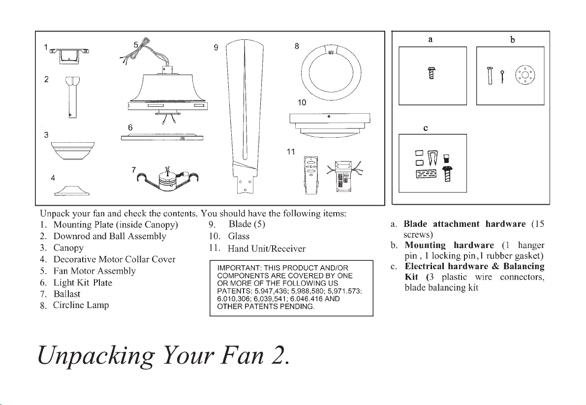
screws #10-32 for outlet box.)
, 2 extra mounting
Page 5
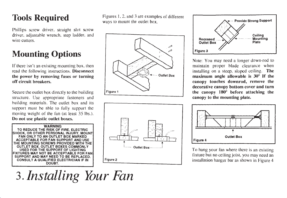
.
Page 6

Hanging the Fan
REMEMBER to turn off the power.
Follow the steps below to hang your fan
properly.
2. Remove the mounting plate from the
canopy by loosening the four screws on
the top of the canopy. Remove the two
non-slotted screws and loosen the slotted
screws. This will enable you to remove
the mounting plate (Figure 6).
NOTE: This ceiling fan is supplied with
two types of hanging assemblies; the
standard ceiling installation using the
downrod with ball and socket mounting,
and the "close-to-ceiling" mounting. The
"close-to-ceiling" mounting is
recommended in rooms with less than
8-foot ceilings or in areas where
additional space is desired from the floor
to the fan blades. When using standard
downrod installation, the distance from
the ceiling to the bottom of the fan blades
will be approximately 12 inches. The
"close-to-ceiling" installation reduces the
distance from the ceiling to the bottom of
the fan blade to approximately 7 inches.
Once you have decided which ceiling
installation you will use, proceed with the
following instructions. Where necessary,
each section of the instructions will note
the different procedures to follow for the
two types of installation.
STANDARD CEILING MOUNTING
1. Remove the canopy ring from the
canopy by turning the ring to the right
until it unlocks (Figure 5).
3. Route the wires exiting the top of the
fan motor through the decorative motor
collar cover then the canopy ring. Make
sure the slot openings are on top. Route
the wires through the canopy and then
through the ball/downrod assembly
(Figure 7).
Turn Canopy Ring to Remove
Figure 5
Loosen but Do Not Remove
Figure 6
Remove
4. Loosen, but do not remove, the set
screws on the collar on the top of the
motor housing.
5. Align the holes at the bottom of the
downrod with holes in the collar on top of
the motor housing (Figure 7). Carefully
insert the hanger pin through the holes in
the collar and downrod. Be careful not to
jam the pin against the wiring inside the
downrod. Insert the locking pin through
the hole near the end of the hanger pin
until it snaps into its locked position.
WARNING
FAILURE TO PROPERLY INSTALL LOCKING
PIN AS NOTED IN STEP 5 COULD RESULT IN
FAN LOOSENING AND POSSIBLY FALLING.
6. Re-tighten the set screws on the collar
on the top of the motor housing.
7. Proceed to "Installing the Fan"
section.
4.
Page 7

Page 8

11
11
Page 9

Making the Electrical
Connections
REMEMBER to disconnect the power. If
you feel that you do not have enough
electrical wiring knowledge or experience,
have your fan installed by a licensed
electrician.
Follow the steps below to connect the fan
to your household wiring. Use the wire
connecting nuts supplied with your fan
and supplied with remote control. Secure
the connectors with electrical tape. Make
sure there are no loose strands or
connections (Figure 13).
Note: This remote control unit is
equipped with 16 code combinations to
prevent possible interference from or to
other remote units.
The frequencies on your receiver and
transmitter have been preset at the
factory, before installing the receiver,
make sure the dip switches on the
receiver and transmitter are set to the
same frequency. The dip switches on
the transmitter are located inside the
battery compartment
1. Insert the receiver into the ceiling
mounting plate with the flat side of the
receiver facing the ceiling.
.
2. Connect both green wires from the
downrod and mounting plate to the bare
copper (Ground) from the electrical box.
3. Connect the black wire (AC IN L)
from the receiver unit to the black wire
from the electrical box.
4. Connect the white wire (AC IN N)
from the receiver unit to the white wire
from the electrical box.
5. Connect the white wire (To Motor
N) from the receiver unit to the white
wire from the fan assembly.
6. Connect the black wire (To Motor
L) from the receiver unit to the black
wire from the fan assembly.
7. Connect the blue wire (For Light)
from the receiver unit to the blue wire
from the fan.
After wires are connected, carefully tuck
them into the electrical box. Insert the
receiver unit into the mounting plate;
make sure the black antenna wire sits on
top of the receiver unit.
WARNING
EACH WIRE NUT (WIRE CONNECTOR)
SUPPLIED WITH THIS FAN IS DESIGNED TO
ACCEPT UP TO ONE 12 GAUGE HOUSE WIRE
AND TWO WIRES FROM THE FAN. IF YOU
HAVE LARGER THAN 12 GAUGE HOUSE
WIRING OR MORE THAN ONE HOUSE WIRE TO
CONNECT TO THE FAN WIRING, CONSULT AN
ELECTRICIAN FOR THE PROPER SIZE WIRE
NUTS TO USE.
Figure 13
7.
Page 10

Finishing the Fan
Installation
STANDARD CEILING MOUNTING
WHEN USING THE STANDARD
BALL/DOWNROD MOUNTING, THE TAB IN
THE RING AT THE BOTTOM OF THE
MOUNTING PLATE MUST REST IN THE
GROOVE OF THE HANGER BALL. FAILURE
TO PROPERLY SEAT THE TAB IN THE
GROOVE COULD CAUSE DAMAGE TO
WIRING.
1. Align the locking slots of the
ceiling canopy with the two screws in
the mounting plate. Push up to engage
the slots and turn clockwise to lock in
place. Immediately tighten the two
mounting screws firmly.
2. Install the remaining two mounting
screws into the holes in the canopy and
tighten firmly.
3. Install the decorative canopy ring
by aligning the ring' s slots with the
screws in the canopy. Rotate the ring
counter-clockwise to lock in place.
4. You may now proceed to attaching
the fan blades.
CLOSE-TO-CEILING MOUNTING
1 Carefully unhook the fan from the
mounting plate and align the locking
slots of the ceiling canopy with the two
WARNING
8.
screws in the mounting plate. Push up to
engage the slots and turn clockwise to
lock in place. Immediately tighten the
two mounting screws firmly.
2. Install the remaining two mounting
screws into the holes in the canopy and
tighten firmly.
3. Install the decorative canopy ring by
aligning the ring's slots with the screws
in the canopy. Rotate the ring counterclockwise to lock in place.
4. You may now proceed to attaching the
fan blades.
LOCKING SLOTS OF CEILING CANOPY ARE
PROVIDED ONLY AS AN AID TO MOUNTING
DO NOT LEAVE FAN ASSEMBLY
UNATTENDED UNTIL ALL FOUR CANOPY
SCREWS ARE ENGAGED AND FIRMLY
TIGHTENED.
Attaching the Fan
Blades
Note : The blade side which marked
with " This Side Up" must toward the
ceiling after it is installed.
1. Insert the blade through the slot cutoff in the center flywheel , align the
three screw holes in the blade with the
screw holes in the flywheel and secure
with screws provided (Figure 14).
2. Repeat for the remaining blades.
WARNING
All blades are grouped by weight.
Because plastic blades vary in density,
the fan may wobble even though the
blades are weight matched.
The following procedure should correct
most fan wobble. Check after each step.
1. Check that all blade and blade
bracket screws are secure.
2. Most fan wobble problems are
caused when blade levels are unequal.
Check this level by selecting a point on
the ceiling above the tip of one of the
blades. Measure from a point on the
center of each blade to the point on the
ceiling. Measure this distance as shown
in Figure 15. Rotate the fan until the next
blade is positioned for measurement.
Repeat for each blade. Measurements
Page 11

deviation should be within 1/8". Run the
fan for 10 minutes.
3. Use the enclosed Blade Balancing
Kit if the blade wobble is still noticeable.
Touching
ceiling
Figure 15
Installing the Light Kit
/ Glass Bowl
CAUTION- To reduce the risk of
electrical shock, disconnect the electrical
supply circuit to the fan before installing
light kit.
1. Remove the three mounting screws
and lockwashers on the black bracket
below the fan motor (Figure 16).
2. Route the Blue wire and White wire
from the fan motor through the center
hole in the light kit plate.
3. Secure the light kit plate to the black
bracket using the three screws and
lockwashers that were removed in step 1.
4. Connect the Blue wire from the fan
motor to the Black wire from the ballast
by connecting the molded adaptor plug;
connect the White wire from the fan
motor to the White wire from the ballast
by connecting the molded adaptor plug
5. Remove the two screws on the light
kit plate.
6. Install the ballast to the light kit plate
using the two screws that were removed
in step 5 (Figure 17).
.
7. With power off, carefully position the
circline lamp (Max. 30 watt, provided)
under the lamp retainer, make sure the 4pins on the circline lamp are located at
the bottom, near the connector from the
ballast. Snap both sides of the lamp
retainer over the circline lamp, carefully
engage the connector from the ballast
with 4-pins on the circline lamp (Figure
18).
9.
Page 12

Page 13

p
Setting the Code
This unit has 16 different code combinations.
To set the code, perform the following steps.
A. Setting the code on the transmitter:
a. Remove battery cover. Press firmly below arrow and
slide battery cover off.
b. Slide code switches to your choice of up or down
position (factory setting is all up).
Black Receiver Wire (AC IN L)
White Receiver Wire(AC IN N)
White Receiver Wire(TO MOTOR N)
Black Receiver Wire(TO MOTOR L)
Blue Receiver Wire(FOR LIGHT)
NOTE: If other fan or supply wires are different color, have
this unit installed by a licensed electrician.
B. Lay the black antenna wire on top of the receiver and slide
the receiver into the mounting plate.
Black Supply Wire
White Supply Wire
White Fan Wire
Black Fan Wire
Blue Light Wire
B. Setting the code on the receiver:
a. Slide code switches to the same position as set on
your transmitter.
b. Replace battery cover on transmitter.
CAUTION: Ceiling angle shall not exceed 30 degrees.
Remote Control Model: UC7067RYK.
Installing Receiver
WARNING: To reduce the risk of fire or electric shock,
remember to disconnect power. Do not use solid state fans,
electrical wire must meet all local and national electrical code
requirement. Electrical source and fans m
Maximum fan motor amps: 1.5, Maximum Tungsten 300 watts,
or, Maximum Ballast 300 VA.
A. Wire connection:
Fan Green Wire
O
ust be 120 volt, 60Hz.
Bare Supply Wire
erating Your Remote Control 11.
Operating Transmitter
NOTE: This remote is equipped with 16 code combinations.
To prevent possible interference from or to other remote units
such as garage door openers, car alarm or security system,
simply change the combination code but be sure that the code
on both transmitter and receiver are matched.
Install a 9 volt battery (not included).
Operating the fan
Hi Key---High Speed
Med Key--Medium Speed
Low Key---Low Speed
Light Key---Light On/Off
Reverse Key ---Fan Reversing Function
Fan Off Key---Fan Off
Page 14

Here are some suggestions to help you
maintain your fan.
1. Because of the fan's natural
movement, some connections may
become loose. Check the support
connections, brackets, and blade
attachments twice a year. Make sure
they are secure. (It is not necessary to
remove fan from ceiling.)
2. Clean your fan periodically to help
maintain its new appearance over the
years. Do not use water when cleaning.
Use only a soft brush or lint-free cloth to
avoid scratching the finish. The plating
is sealed with a lacquer to minimize
discoloration or tarnishing. This could
damage the motor, or the wood or
possibly cause an electrical shock.
3. You can apply a light coat of furniture
polish to the wood for additional
protection and
small scratches with a light application
of shoe polish.
enhanced beauty. Cover
4. There is no need to oil your fan.
The motor has permanently lubricated
sealed ball bearings.
WARNING
MAKE SURE THE POWER IS OFF AT THE
ELECTRICAL PANEL BOX BEFORE YOU
ATTEMPT ANY REPAIRS. REFER TO THE
SECTION, "MAKING ELECTRICAL
CONNECTIONS."
12.Care of Your Fan
Page 15

Problem Solution
Fan will not start.
1. Check main and branch circuit fuses or breakers.
2. Check line wire connections to the fan and switch wire connections in the switch housing.
CAUTION: Make sure main power is off.
3. Check battery in the transmitter. Does the red LED light come on? Are you standing close enough
to the fan (normal range is 10-20 feet)? Are the dip switch settings the same on the transmitter
(hand unit) and receiver? REMEMBER TO TURN OFF POWER SUPPLY BEFORE
CHECKING THE DIP SWITCH SETTINGS IN RECEIVER.
Fan sounds noisy.
1. Make sure all motor housing screws are snug.
2. Make sure the screws that attach the fan blade bracket to the motor hub are tight.
3. Make sure wire nut connections are not rattling against each other or the interior wall of the switch
housing.
CAUTION: Make sure main power is off.
4. Allow a 24-hour "breaking-in" period. Most noises associated with a new fan disappear during this
time.
5.
If using the Ceiling Fan light kit, make sure the screws securing the glassware are tight. Check that
the light bulb is also secure.
6. Make sure the canopy is a short distance from the ceiling.
It should not touch the ceiling.
7. Make sure your ceiling box is secure and rubber isolator pads were used between the hanger
bracket and ceiling box.
Troubleshooting 13.
Page 16

1740
10
174
3724
5958
30
64
124
93
 Loading...