

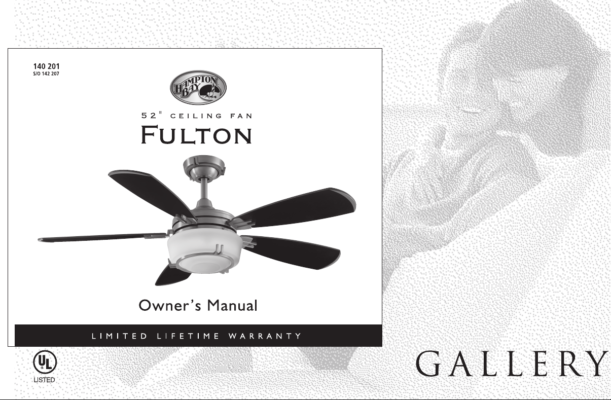
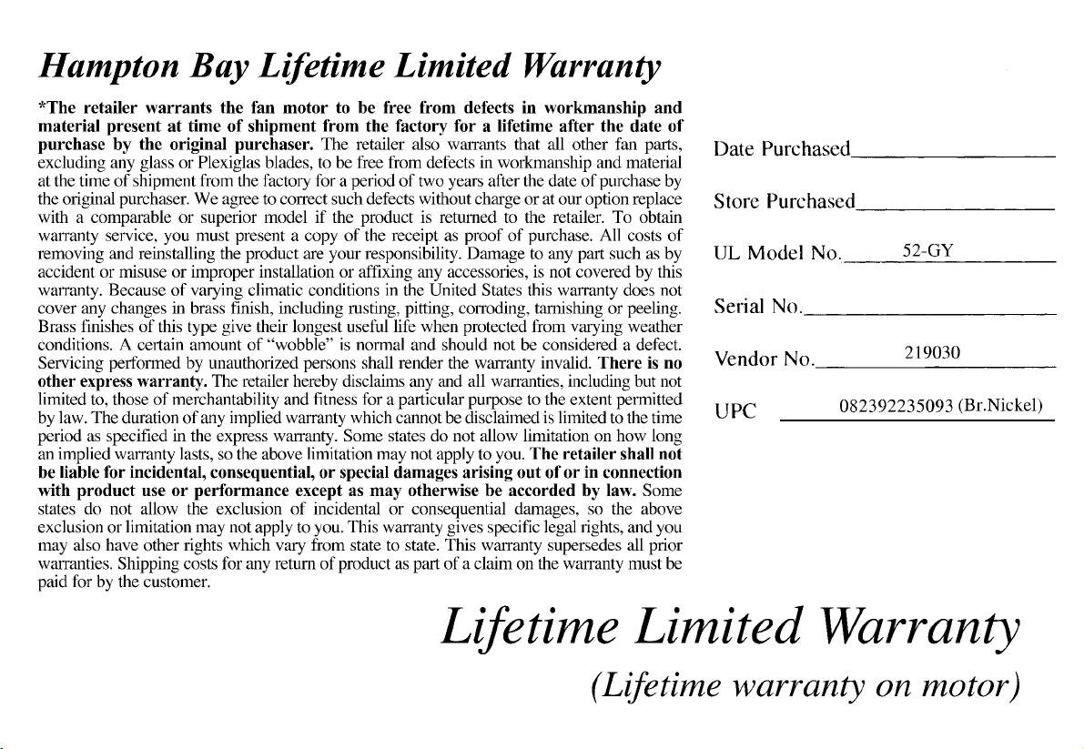
Page 1
Page 2
Page 3
Page 4
Page 5
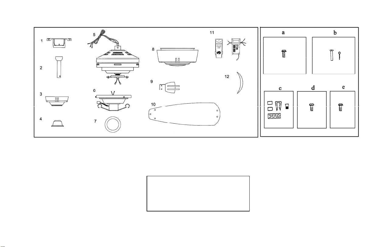
Unpack your fan and check the contents. You should have the following items:
1. Mounting Plate (inside Canopy)
2. Downrod and Ball Assembly
3. Canopy
4. Decorative Motor Collar Cover
5. Fan Motor Assembly
6. Light Kit Assembly
7. Circline Lamp (1)
8. Glass (1)
9. Blade Bracket Set (5)
10. Blades (5)
11. Hand Unit/Receiver
12. Blade Accent (5)
IMPORTANT: THIS PRODUCT AND/OR
COMPONENTS ARE COVERED BY ONE
OR MORE OF THE FOLLOWING US
PATENTS: 5,947,436; 5,988,580; 5,971.573:
6.010,306; 6,039,541; 6.046.416 AND
OTHER PATENTS PENDING.
Unpacking Your Fan 2.
a. Blade attachment hardware (15
screws)
b. Mounting hardware (1 hanger pin ,
1 locking pin)
c. Electrical hardware & Balancing
Kit (3 plastic wire connectors, blade
balancing kit)
d. Blade Bracket hardware (10
screws and lockwashers)
e. Blade Accent hardware (10 screws)
Page 6

Page 7

Hanging the Fan
REMEMBER to turn off the power.
Follow the steps below to hang your fan
properly.
NOTE: This fan is recommended for the
until it unlocks (Figure 5).
2. Remove the mounting plate from
the canopy by loosening the four screws
on the top of the canopy. Remove the
two non-slotted screws and loosen the
slotted screws. This will enable you to
remove the mounting plate (Figure 6).
standard ceiling mounting using the
downrod provided with this fan. When
using standard ceiling installation with
an 6 inch downrod provided, the
distance from the ceiling to the bottom
of the fan blades will be approximately
11 inches.
THE FAN MUST BE MOUNTED WITH A
MINIMUM OF 7 FEET CLEARANCE FROM
THE TRAILING EDGE OF THE BLADES TO
THE FLOOR.
Figure 5
Loosen but Do Not Remove
IF YOU FEEL THAT YOU DO NOT
HAVE ENOUGH ELECTRICAL
WIRING KNOWLEDGE OR
EXPERIENCE, HAVE YOUR FAN
INSTALLED BY A LICENSED
ELECTRICIAN.
STANDARD CEILING
MOUNTING
1. Remove the canopy ring from the
canopy by turning the ring to the left
Remove
Figure 6
3. Route the wires exiting the top of
the fan motor through the decorative
motor collar cover then the canopy ring.
Make sure the slot openings are on top.
Route the wires through the canopy and
then through the ball/downrod assembly
(Figure 7).
4. Loosen, but do not remove, the set
Turn Canopy Ring to Remove
screws on the collar on the top of the
motor housing.
5. Align the holes at the bottom of the
downrod with holes in the collar on top
of the motor housing (Figure 7).
Carefully insert the hanger pin through
the holes in the collar and downrod. Be
careful not to jam the pin against the
wiring inside the downrod. Insert the
locking pin through the hole near the end
of the hanger pin until it snaps into its
locked position.
FAILURE TO PROPERLY INSTALL
LOCKING PIN AS NOTED IN STEP 5
COULD RESULT IN FAN LOOSENING AND
POSSIBLY FALLING.
WARNING
6. Re-tighten the set screws on the
collar on the top of the motor housing.
7. Make sure the grommet is properly
installed in the collar cover, then slide
the collar cover on the downrod until it
rests on the motor housing. Be sure that
the canopy and the collar cover are both
oriented correctly.
8. Proceed to "Installing the Fan"
section.
4.
Page 8

Figure 7
5.
Installing Fan to the
Electrical Box
WHEN MOUNTING THE FAN ON A SLOPED
CEILING, THE STANDARD BALL/DOWNROD
MOUNTING METHOD MUST BE USED. THE
MOUNTING PLATE MUST BE MOUNTED SO
THAT THE SLOT OPENINGS ARE ON THE
LOWER SIDE BY SLIDING THE MOUNTING
PLATE FROM THE TOP DOWN
1. Pass the 120-volt supply wires
through the center hole in the ceiling
mounting plate as shown in Figure 8.
2. Install the ceiling mounting plate
on the electrical box by sliding the
mounting screws provided with the
outlet box (Figure 8). If necessary, use
leveling washers (not included) between
the mounting plate and the electrical box.
Note that the flat side of the mounting
plate is toward the electrical box (Figure 8).
Figure 8
CAUTION
3. Securely tighten the two mounting
screws.
4. Carefully lift the fan assembly up to
the ceiling mounting plate. Make sure
the tab on the mounting plate is properly
seated in the groove in the hanger ball.
Making the Electrical
Connections
REMEMBER to disconnect the power. If
you feel that you do not have enough
electrical wiring knowledge or experience,
have your fan installed by a licensed
electrician.
Follow the steps below to connect the fan
to your household wiring. Use the wire
connecting nuts supplied with your fan
and supplied with remote control. Secure
the connectors with electrical tape. Make
sure there are no loose strands or
connections (Figure 9).
l. Connect both green wires from the
downrod and mounting plate to the bare
copper (Ground) from the electrical box.
2. Connect the black wire (AC IN L)
from the receiver unit to the black wire
from the electrical box.
3. Connect the white wire (AC IN N)
from the receiver unit to the white wire
from the electrical box.
4. Connect the white wire (To Motor N)
Page 9

from the receiver unit to the white wire
from the fan assembly.
5. Connect the black wire (To Motor L)
from the receiver unit to the black wire
from the fan assembly.
6. Connect the blue wire (For Light)
from the receiver unit to the blue wire
from the fan.
After wires are connected, carefully tuck
them into the electrical box. Insert the
receiver unit into the mounting plate;
make sure the black antenna wire sits on
top of the receiver unit.
THE FREQUENCIES ON YOUR RECEIVER AND
TRANSMITTER HAVE BEEN PRESET AT THE
FACTORY, BEFORE INSTALLING THE
RECEIVER, MAKE SURE THE DIP SWITCHES
ON THE RECEIVER AND TRANSMITTER ARE
SET TO THE SAME FREQUENCY. THE DIP
SWITCHES ON THE TRANSMITTER ARE
LOCATED INSIDE THE BATTERY
COMPARTMENT.
EACH WIRE NUT (WIRE CONNECTOR)
SUPPLIED WITH THIS FAN IS DESIGNED TO
ACCEPT UP TO ONE 12 GAUGE HOUSE WIRE
AND TWO WIRES FROM THE FAN. IF YOU
HAVE LARGER THAN 12 GAUGE HOUSE
WIRING OR MORE THAN ONE HOUSE WIRE TO
CONNECT TO THE FAN WIRING, CONSULT AN
ELECTRICIAN FOR THE PROPER SIZE WIRE
NUTS TO USE.
NOTE
WARNING
Figure 9
Finishing the Fan
Installation
STANDARD CEILING MOUNTING
WHEN USING THE STANDARD
BALL/DOWNROD MOUNTING, THE TAB IN
THE RING AT THE BOTTOM OF THE
MOUNTING PLATE MUST REST IN THE
GROOVE OF THE HANGER BALL. FAILURE
TO PROPERLY SEAT THE TAB IN THE
GROOVE COULD CAUSE DAMAGE TO
WIRING.
WARNING
1. Align the locking slots of the
ceiling canopy with the two screws in
the mounting plate. Push up to engage
the slots and turn clockwise to lock in
place. Immediately tighten the two
mounting screws firmly.
2. Install the remaining two mounting
screws into the holes in the canopy and
tighten firmly.
3. Install the decorative canopy ring
by aligning the ring' s slots with the
screws in the canopy. Rotate the ring
clockwise to lock in place.
4. You may now proceed to attaching
the fan blades.
6.
Page 10

Attaching the Fan
remaining blades.
Blades
NOTE: Your fan blades are reversible,
select the blade side finish which best
accentuates your decor.
1. Attach the blade accent to the blade
tip by using the screws supplied (Figure
10).
2. Attach blade to blade bracket, using
the washer head screws supplied (Figure
10). Please note that the rubber washers
are pre-attached to the blade bracket.
Start a screw into the bracket. Repeat for
the two remaining screws.
3.
Tighten each screw securely.
4. Insert the blade assembly through
the slot cut-out in the center flywheel,
align the two screw holes in the blade
bracket with the screw holes in the
flywheel and secure with screws and
lockwashers provided (Figure 11).
5. Repeat steps 1, 2, 3 & 4 for the
All blades are grouped by weight.
Because natural woods vary in density,
the fan may wobble even though the
blades are weight matched.
The following procedure should correct
most fan wobble. Check after each step.
1. Check that all blade and blade
bracket screws are secure.
2. Most fan wobble problems are
caused when blade levels are unequal.
Check this level by selecting a point on
the ceiling above the tip of one of the
blades. Measure from a point on the
center of each blade to the point on the
ceiling. Measure this distance as shown
in Figure 12. Rotate the fan until the next
blade is positioned for measurement.
Repeat for each blade. Measurements
deviation should be within 1/8". Run the
fan for 10 minutes.
3. Use the enclosed Blade Balancing
Kit if the blade wobble is still noticeable.
Touching
ceiling
TO REDUCE THE RISK OF PERSONAL INJURY,
DO NOT BEND THE BLADE HOLDERS WHILE
INSTALLING, BALANCING THE BLADES, OR
CLEANING THE FAN. DO NOT INSERT
FOREIGN OBJECTS BETWEEN ROTATING FAN
BLADES.
WARNING
7
Page 11

Installing the Light Kit
/ Glass Bowl
CAUTION- To reduce the risk of
electrical shock, disconnect the electrical
supply circuit to the fan before installing
light kit
1. Remove the three mounting screws
and lockwashers on the black bracket
below the fan motor (Figure 13).
2. Connect the Blue wire from the fan
motor to the Black wire from the light kit
assembly by connecting the molded
adaptor plug; connect the White wire
.
from the fan motor to the White wire
from the light kit assembly by
connecting the molded adaptor plug.
3. Secure the light kit assembly to the
black bracket using the three screws and
lockwashers that were removed in step 1.
4. Remove the three mounting screws on
the side of the light kit assembly (Figure
14)
5. With power off, install the circline
lamp (Max. 30W, provided) to the lamp
bracket pre-assembled in the light kit
assembly and engage the connector from
the ballast of the light kit assembly
with the 4-pins on the circline lamp ,
make sure they are engaged properly
(Figure 14).
6. Install the glass bowl to the light kit
assembly and finger tighten with three
mounting screws that were removed in
step 4.
8
Page 12

The hand unit controls directions
(forward or reverse).
Speed settings for warm or cool weather
depend on factors such as the room size,
ceiling height, number of fans, and so on.
Warm weather- (Forward) A
downward air flow creates a cooling
effect as shown in Figure 15. This allows
you to set your air conditioner on a
higher setting without affecting your
comfort.
Cool weather- (Reverse) An upward
airflow moves warm air off the ceiling
area as shown in Figure 16. This allows
you to set your heating unit on a lower
setting without affecting your comfort.
9.Operating You Fan
Figure 15
Figure 16
Page 13

Setting the Code
This unit has 16 different code combinations.
To set the code, perform the following steps.
A. Setting the code on the transmitter:
a. Remove battery cover. Press firmly below arrow and
slide battery cover off.
b. Slide code switches to your choice of up or down
position (factory setting is all up).
B. Setting the code on the receiver:
a. Slide code switches to the same position as set on
your transmitter.
b. Replace battery cover on transmitter.
CAUTION: Ceiling angle shall not exceed 30 degrees.
Remote Control Model: UC7067RK
Black Receiver Wire (AC IN L)
White Receiver Wire(AC IN N)
White Receiver Wire(TO MOTOR N)
Black Receiver Wire(TO MOTOR L)
Blue Receiver Wire(FOR LIGHT)
NOTE: If other fan or supply wires are different color, have
this unit installed by a licensed electrician.
B. Lay the black antenna wire on top of the receiver and slide
the receiver into the mounting plate.
Black Supply Wire
White Supply Wire
White Fan Wire
Black Fan Wire
Blue Light Wire
Operating Transmitter
NOTE: This remote is equipped with 16 code combinations.
To prevent possible interference from or to other remote units
such as garage door openers, car alarm or security system,
simply change the combination code but be sure that the code
on both transmitter and receiver are matched.
Install a 9 volt battery (not included).
Installing Receiver
WARNING: To reduce the risk of fire or electric shock,
remember to disconnect power. Do not use solid state fans,
electrical wire must meet all local and national electrical code
requirement. Electrical source and fans must be 115/120 volt,
60Hz. Maximum fan motor amps: 1.0. Maximum light watts:
300-incandescent/ fluorescent.
A. Wire connection:
Fan Green Wire
Operating Your Remote Control 10.
Bare Supply Wire
Operating the fan
Hi Key---High Speed
Med Key--Medium Speed
Low Key---Low Speed
Light Key---Light On/Off
Reverse Key ---Fan Reversing Function
Fan Off Key---Fan Off
Page 14

Here are some suggestions to help you
maintain your fan.
1. Because of the fan's natural
movement, some connections may
4. There is no need to oil your fan.
The motor has permanently lubricated
sealed ball bearings.
become loose. Check the support
connections, brackets, and blade
attachments twice a year. Make sure
they are secure. (It is not necessary to
remove fan from ceiling.)
2. Clean your fan periodically to help
maintain its new appearance over the
years. Do not use water when cleaning.
Use only a soft brush or lint-free cloth to
avoid scratching the finish. The plating
is sealed with a lacquer to minimize
discoloration or tarnishing. This could
damage the motor, or the wood or
possibly cause an electrical shock.
3. You can apply a light coat of
furniture polish to the wood for
additional protection and enhanced
beauty. Cover small scratches with a
light application of shoe polish.
MAKE SURE THE POWER IS OFF AT THE
ELECTRICAL PANEL BOX BEFORE YOU
ATTEMPT ANY REPAIRS. REFER TO THE
SECTION, "MAKING ELECTRICAL
CONNECTIONS."
11.Care of Your Fan
WARNING
Page 15

Problem Solution
Fan will not start.
Fan sounds noisy.
1. Check main and branch circuit fuses or breakers.
2. Check line wire connections to the fan and switch wire connections in the switch housing.
CAUTION: Make sure main power is off.
3. Check battery in the transmitter. Does the red LED light come on? Are you standing close enough
to the fan (normal range is 10-20 feet)? Are the dip switch settings the same on the transmitter
(hand unit) and receiver? REMEMBER TO TURN OFF POWER SUPPLY BEFORE
CHECKING THE DIP SWITCH SETTINGS IN RECEIVER.
1. Make sure all motor housing screws are snug.
2. Make sure the screws that attach the fan blade bracket to the motor hub are tight.
3. Make sure wire nut connections are not rattling against each other or the interior wall of the switch
housing.
CAUTION: Make sure main power is off.
4. Allow a 24-hour "breaking-in" period. Most noises associated with a new fan disappear during this
time.
5. If using the Ceiling Fan light kit, make sure the screws securing the glassware are tight. Check that
the light bulb is also secure.
6. Make sure the canopy is a short distance from the ceiling.
It should not touch the ceiling.
7. Make sure your ceiling box is secure and rubber isolator pads were used between the hanger
bracket and ceiling box.
Troubleshooting 12.
Page 16

 Loading...