

Page 1

Page 2
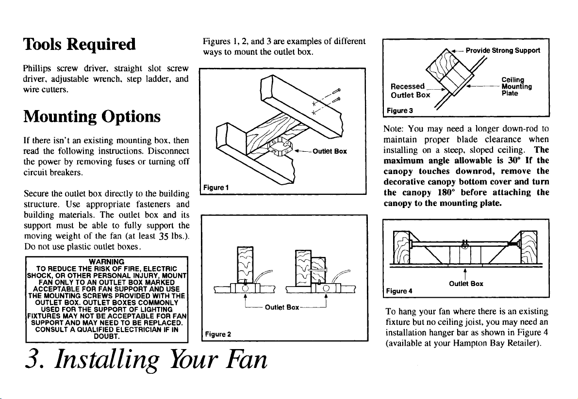
Page 3
READ AND SAVE THESE INSTRUCTIONS
1. To reduce the risk of electric shock, insure electricity has
9. After marking electrical connections, spliced conductors
been turned off at the circuit breaker or fuse box before
beginning.
2. All wiring must be in accordance with the National
Electrical Code (ANSI / NFPA 70-1999 ) and local
electrical codes. Electrical installation should be
NOTE: The important safeguards and instructions
performed by a qualified licensed electrician.
3. CAUTION: To reduce the risk of personal injury, use only
the screws provided with the outlet box.
4. The outlet box and support structure must be securely
mounted and capable of reliably supporting a minimum of
35 pounds. Use only UL Listed outlet boxes marked "FOR
FAN SUPPORT."
WARNING
TO REDUCE THE RISK OF FIRE, ELECTRIC SHOCK OR PERSONAL
INJURY, MOUNT FAN TO OUTLET BOX MARKED ACCEPTABLE FOR
FAN SUPPORT WITH THE SCREWS PROVIDED WITH THE OUTLET
BOX.
This Fan is suitable for wet location. Suitable for Use In
5. The fan must be mounted with a minimum of 7 feet
clearance from the trailing edge of the blades to the floor.
6. Avoid placi ng o bject s in the pat h o f the bl ades .
7. To avoid personal injury or damage to the fan and other
items, be cautious when working around or cleaning the
fan.
8. Do not use water or detergents when cleaning the fan or
fan blades. A dry dust cloth or lightly dampened cloth
will be suitable for most cleaning.
1.Safety Rules
should be turned upward and pushed carefully up into outlet
box. The wires should be spread apart with the grounded
conductor and the equipment-grounding conductor on o ne
side of the outlet box.
appearing in this manual are not meant to cover all possible
conditions and situations that may occur. It must be
understood that common sense, caution and care are factors
which can not be built into this product. These factors must
be supplied by the person(s) installing caring for and
operating the unit.
Wet Locations When Installed In A GFCI Protected
Branch Circuit.
Use only with light with light kits marked"Suitable for
use in wet locations"
TO REDUCE THE RISK OF PERSONAL INJURY, DO NOT BEND THE
BLADE BRACKETS (ALSO REFERRED TO AS "FLANGES") DURING
ASSEMBLY OR AFTER INSTALLATION. DO NOT INSERT OBJECTS IN
THE PATH OF THE BLADES.
TO REDUCE THE RISK OF SHOCK. THIS FAN MUST BE INSTALLED
WITH AN ISOLATION CONTROL/SWITCH. TO REDUCE THE RISK OF
FIRE OR ELECTRIC SHOCK, THIS FAN SHOULD ONLY BE USED WITH
FAN SPEED CONTROL PART NO.
RHINE ELECTRIC CO., LTD.
.
WARNING
WARNING
UC-7067RC, MANUFACTURED BY
Page 4

Unpack your fan and check the contents. You should have the following items:
1. Blades (5)
2. Blade brackets (5)
3. Decorative faceplates (5)
4. Canopy
5. Deco rative motor collar cover
6. Fan motor assembly
7. Light kit plate
8. Ball/Down rod assembly
9. Wiring case assembly
10a. Hand held remote transmitter.
10b. Receiver with 6 wire Nuts
11. 25W bulbs (3)
12. Glass Shade
13. Support bracket
This product and/or components are
covered by one or more of the following
U.S. patents: 5,947,436; 5,988,580;
5,971,573; 6,010,110; 6,010,306;
6,039,541; 6,046,416 and other patents
pending.
IMPORTANT
Unpacking Your Fan 2.
d
a. Blade attachment hardware
(One group of 15 screws and spring
washers to attach the blade bracket set,
decorative faceplates to the blades. The
other group of 15 screws and spring
washers to attach the blade bracket set to
the fan motor assembly)
b. Mounting hardware
(1 bolt, 1 clevis pin ,1 rubber gasket )
c. Electrical hardware & Balancing kit
(3 plastic wire connectors, blade
balancing kit )
d. 1 decorative nut
Page 5
Page 6

Hanging the Fan
REMEMBER to turn off the power.
Follow the steps below to hang your fan
properly.
NOTE: This ceiling fan is supplied with
two types of hanging assemblies; the
standard ceiling installation using the
downrod with ball and socket mounting,
and the "close-to-ceiling" mounting. The
"close-to-ceiling" mounting is
recommended in rooms with less than
8-foot ceilings or in areas where
additional space is desired from the floor
to the fan blades. When using standard
downrod installation, the distance from
the ceiling to the bottom of the fan
blades will be approximately 12 inches.
The "close-to-ceiling" installation
reduces the distance from the ceiling to
the bottom of the fan blades to
approximately 9 inches.
Once you have decided which ceiling
installation you will use, proceed with
the following instructions. Where
necessary, each section of the
instructions will note the different
procedures to follow for the two types of
installation.
OPTION 1: STANDARD CEILING
MOUNTING
1. Remove the hanger bracket from
the canopy by removing the four screws
on the top of the canopy (Figure 5).
Figure 5
2. Route the wires exiting the top of
the fan motor through the motor collar
cover. Route the wires through the
canopy and then through the ball/
downrod assembly (Figure 6).
3. Loosen, but do not remove, the 2
set screws on the collar on the top of the
motor housing.
4. Align the holes at the bottom of the
downrod with holes in the collar on top
of the motor housing (Figure 6).
Carefully insert the bolt through the
holes in the collar and downrod. Be
careful not to jam the bolt against the
wiring inside the downrod. Insert clevis
pin and bend to ensure security, as noted
in the circle inset of Figure 6.
5. Tighten the two screws on top of
the fan motor firmly and slide down the
motor collar cover (Figure 6).
FAILURE TO PROPERLY INSTALL LOCKING PIN
AS NOTED IN STEP 4 COULD RESULT IN FAN
LOOSENING AND POSSIBL Y FALLING.
WARNING
4.
Page 7

Page 8

Page 9

Making the Electrical
g
Connections
REMEMBER to shut the power off at
the circuit breaker or fuse box.
NOTE: (Fig.12) This remote control unit
is equipped with 16 code combinations to
prevent possible interference from or to
other remote units. The frequency switches
on your receiver and transmitter have been
preset at the factory. Please recheck to
make sure the switches on wall transmitter
and receiver are set to the same position,
any combination of settings will operate
the fan as long as the wall transmitter and
receiver are set to the same position.
Because the frequency switches are small,
please use a fine point instrument to adju st
the setting.
Step 1 . (Fig.13) Insert the receiver into the
hanger bracket with the flat side of the
receiver facing the ceiling.
Fi
12
Step 2. Motor to Receiver Electrical
Connections: Connect the Black wire from
the fan to Black wire marked “To Motor
L” from the receiver. Connect the White
wire from the fan to the White wire
marked “To Motor N” from the receiver.
Connect the Blue wire from the fan to the
Blue wire marked “For Light” from the
Receiver. Secure wire connections with
the plastic wire nuts provided.
Ste p 3. (Fig.14) Receiver to House Supply
Wires Electrical Connections:
Connect the Black (hot) wire from the
ceiling to the Black wire marked "AC in
L" from the Receiver. Connect the White
(neutral) wire from the ceiling to the
White wire marked "AC in N" from the
Receiver. Secure wire connections with
the plastic wire nuts provided.
Step 4. If your outlet has a ground wire
(Green or Bare Copper), connect the fan
ground wires (on hanger ball and hanger
bracket) to it; otherwise, connect the fan
ground wire on hanger ball directly to
hanger bracket.
Fig 13
NOTE: Fan must be installed at a
maximum distance of 40ft from the
transmitting unit for proper signal
transmission between the transmitting unit
and the fan's receiving unit.
Fig 14
7.
Page 10

Finishing the Fan
Installation
WHEN USING THE STANDARD
BALL/DOWNROD MOUNTING, THE TAB IN
THE RING AT THE BOTTOM OF THE
MOUNTING PLATE MUST REST IN THE
GROOVE OF THE HANGER BALL. FAILURE
TO PROPERLY SEAT THE TAB IN THE
GROOVE COULD CAUSE DAMAGE TO
WIRING.
OPTION 1: STANDARD CEILING
MOUNTING
STANDARD CEILING MOUNTING
1. Align the holes of the ceiling
canopy with the screw holes in the
hanger bracket, secure them with the
screws removed in previous step.
2. You may now proceed to attaching
the fan blades.
OPTION 2: CLOSE-TO-CEILING
MOUNTING
WARNING
LOCKING SLOTS OF CEILING CANOPY ARE
PROVIDED ONLY AS AN AID TO MOUNTING.
DO NOT LEAVE FAN ASSEMBLY
UNATTENDED UNTIL ALL FOUR CANOPY
SCREWS ARE ENGAGED AND FIRMLY
TIGHTENED.
WARNING
Attaching the
Fan Blades
1. Attach blade to blade bracket and
decorative faceplate using the screws
and spring washers provided as shown in
Fig 15.
2. Tighten each screw securely.
3. Fasten the blade assembly to the fan
motor assembly by inserting the blade
bracket into the slot around the motor
housing and tightening the motor screws.
(Figure 16)
4. Repeat steps 1 2 & 3 for the
remaining blades.
Figure 16
1. Carefully unhook the fan from the
mounting plate and align th e holes of the
ceiling canopy with the screw holes in
the hanger bracket, secure them with the
screws removed in previous step.
2. You may now proceed to attaching
the fan blades.
Figure 15
8.
Page 11

Attaching the Light Kit
1. Loosen the screws pre-attached to the
bottom of the motor and mount the light
kit plate to the fan motor assembly by
aligning the screw holes.
2. Tighten it with the screws removed in
step 1.
3. Carefully plug the quick -connect
terminal from the fan motor assembly to
the lead wire from the wiring housing
assembly .
4. Secure the wiring housing to the light
kit plate with the three screws provided.
(Figure 17)
Figure 17
Installing the Bulb and
Glass
SHUT OFF POWER SUPPLY BEFORE
REMOVING OR REPLACING THE
BULB.ALLOW AT LEAST 10 MINUTES BEFORE
CHANGING THE BULB.USE LIGHT BULB IN
ACCORDANCE WITH THE FAN’S
SPECIFICATIONS.DO NOT EXCEED THE
MAXIMUM WATTAGE.
WARNING
1. Install the bulbs (provided) to the
light sockets.
2. Put glass shade into light kit plate,
and then attach the support bracket to the
bolt end of the wiring housing .
3. Secure the glass shade and support
bracket with the decorative nut provided.
(Figure 18)
Figure 18
Blade Balancing
All blades are grouped by weight.
Because natural woods vary in density,
the fan may wobble even though the
blades are weight matched.
The following procedure should correct
most fan wobble. Check after each step.
1. Check that all blade and blade
bracket screws are secure.
2. Most fan wobble problems are
caused when blade levels are unequal.
Check this level by selecting a point on
the ceiling above the tip of one of the
blades. Measure from a point on the
center of each blade to the point on the
ceiling. Measure this distance as shown in
Figure 19. Rotate the fan until the next
blade is positioned for measurement.
Repeat for each blade. Measurements
deviation should be within 1/8". Run the
fan for 10 minutes.
3. Use the enclosed Blade Balancing
Kit if the blade wobble is still noticeable.
Figure 19
TO REDUCE THE RISK OF PERSONAL
INJURY, DO NOT BEND THE BLADE HOLDERS
WHILE INSTALLING, BALANCING THE
BLADES, OR CLEANING THE FAN. DO NOT
INSERT FOREIGN OBJECTS BETWEEN
ROTATING FAN BLADES.
WARNING
9.
Page 12

Operation the
Remote Control
1. Light Button:
Press and release the button to turn the
light ON or OFF. Press and hold the
button to set the desired light brightness.
The light will cycle between bright and
dim settings as long as the button is
pressed. The light key has an automatic
auto-resume feature that allows the light
to remain at the same brightness as the
last time it was turned off.
2. Speed Buttons
Press and release the button for the
desired speed.
3. Fan Off Button
This button turns the power off for the
fan.
Here are some suggestions to help you
maintain your fan.
1. Because of the fan's natural
movement, some connections may
become loose. Check the support
connections, brackets, and blade
attachments twice a year. Make sure
they are secure. (It is not necessary to
remove fan from ceiling.)
2. Clean your fan periodically to help
maintain its new appearance over the
years. Do not use water when cleaning.
Use only a soft brush or lint-free cloth to
avoid scratching the finish. The plating
is sealed with a lacquer to minimize
discoloration or tarnishing. This could
damage the motor, or the wood or
possibly cause an electrical shock.
3. You can apply a light coat of
furniture polish to the wood for
additional protection and enhanced
beauty. Cover small scratches with a
light application of shoe polish.
10.Care of Your Fan
4. There is no need to oil your fan.
The motor has permanently lubricated
sealed ball bearings.
WARNING
MAKE SURE THE POWER IS OFF AT THE
ELECTRICAL PANEL BOX BEFORE YOU
ATTEMPT AN Y REPAIRS. REFER TO THE
SECTION, "MAKING ELECTRICAL
CONNECTIONS."
Page 13

Page 14

 Loading...