


OPERATION MANUAL
User’s Guide
King-Long XMQ6900 Series Tourist Bus
Xiamen King Long United Automotive Industry Co., Ltd.

Foreword
1-1
FOREWORD
King-Long XMQ6900 series tourist bus keeps features of superior economy,
security and comfort. It has stable performance, strong power, luxury interior
trimming and high speed, which could meet applications of passenger inter-city
transportation, touring and business affairs, etc.
As for the specifications introduced in relate to information of the driving
and operation, service and maintenance of the XMQ6900 series tourist bus,
please read them carefully and make proper operation, maintenance and repair so
as to ensure it in good condition. Special hint: without authorization of Xiamen
King Long United Automotive Industry Co., Ltd, never modify the electrical
deployment of the whole vehicle, and should not lap the power supply line in
disorder. Improper usage and repair may have a strong impact on service
performance of the complete vehicle, and thus the manufacturer , Xiamen King
Long United Automotive Industry Co., Ltd. will not takes the responsibility for
the damages caused by them.
Any problem in service, please contact our special maintenance network or
after-sales department. We will ensure timely and complete maintenance as well
as original parts supply.
In order to satisfy all kinds of different demand of the consumers, we strive
to improve the quality of the product continuously to optimize our products. We
should not give any further notice for any modification of the product in advance .
The contents on the instruction book can only be used as reference. If there are
facts not comply with the manual, will be subject to the actual state of the
products because for some device and items, the vehicle will be finally equipped
only if they have been taken as optional configurations.
Final interpretive right of the instruction book belongs to the Engineering
Academy of Xiamen King Long United Automotive Industry Co., Ltd.
Xiamen King Long United Automotive Industry Co., Ltd.
MAY. 2016

Contents
1-2
Contents
Vehicle’s Picture
1. Foreword---------------------------------------------------------------------------------------------------------1-1
Contents
Contents--------------------------------------------------------------------------------------------------------------1-2
2. Technical parameters and complete vehicle description
Technical parameters ----------------------------------------------------------------------------------------------2-1
Introduction to data plate------------------------------------------------------------------------------------------2-2
Product quality assurance -----------------------------------------------------------------------------------------2-3
Technical document ------------------------------------------------------------------------------------------------2-3
Vehicle body structure----------------------------------------------------------------------------------------------2-4
Schematic illustration of the driver zone-------------------------------------------------------------------------2-5
3 . Operation Instruction
Instrument instruction----------------------------------------------------------------------------------------------3-1
Illustration of switch and indicators----------------------------------------------------------------------------3-2
Air conditioner control panel--------------------------------------------------------------------------------------3-3
Transmission operation---------------------------------------------------------------------------------------------3-4
ABS operation-------------------------------------------------------------------------------------------------------3-5
ECAS operation-----------------------------------------------------------------------------------------------------3-6
Open or close the passenger door---------------------------------------------------------------------------------3-7
Door emergency switch--------------------------------------------------------------------------------------------3-8
Adjustment of the driver's seat------------------------------------------------------------------------------------3-9
Horn button---------------------------------------------------------------------------------------------------------3-10
Adjustment of the steering wheel-------------------------------------------------------------------------------3-11
Ignition switch-----------------------------------------------------------------------------------------------------3-12
Lamplight operating handles-------------------------------------------------------------------------------------3-13
Wiper operating handle-------------------------------------------------------------------------------------------3-14
Passenger control panel-------------------------------------------------------------------------------------------3-16
Safety hatch--------------------------------------------------------------------------------------------------------3-17

Contents
1-2
Safety hammer-----------------------------------------------------------------------------------------------------3-18
Relays & Fuses----------------------------------------------------------------------------------------------------3-19
Switch control box------------------------------------------------------------------------------------------------3-20
4 . Vehicle starting and driving
Check oil level of the engine--------------------------------------------------------------------------------------4-1
Check level of the coolant-----------------------------------------------------------------------------------------4-2
Check fuel pre-filter with water separator-----------------------------------------------------------------------4-3
Check fuel level-----------------------------------------------------------------------------------------------------4-4
Check vehicle lighting, intermittent lights and brake lights-------------------------------------------------4-5
Check the level of AdBlue and the daily maintenance of SCR system--------------------------------------4-6
Drain water in air tank----------------------------------------------------------------------------------------------4-7
Check engine oil pressure------------------------------------------------------------------------------------------4-8
Check Pneumatic pressure-----------------------------------------------------------------------------------------4-9
Check Tachometer working order-------------------------------------------------------------------------------4-10
Steering wheel play------------------------------------------------------------------------------------------------4-11
Check tire for abrasion and pressure and tire nut for fixture------------------------------------------------4-12
Air cleaner----------------------------------------------------------------------------------------------------------4-13
General leakages (water, oil, fluids and fuel) -----------------------------------------------------------------4-14
Fastening and state of seat belts---------------------------------------------------------------------------------4-15
Check emergency devices and driver’s tools (fire extinguisher) -------------------------------------------4-16
Windshield wipers and conditions of wiper blades and arms-----------------------------------------------4-17
Electrical rearview mirror----------------------------------------------------------------------------------------4-18
Power steering system--------------------------------------------------------------------------------------------4-19
General state and tension of drive belts------------------------------------------------------------------------4-21
Check level of battery electrolyte-------------------------------------------------------------------------------4-22
Procedures for engine start up-----------------------------------------------------------------------------------4-23
Engine shut down-------------------------------------------------------------------------------------------------4-24
Engine start up and shut down in the engine compartment--------------------------------------------------4-25
Starting the vehicle------------------------------------------------------------------------------------------------4-26
Parking the vehicle------------------------------------------------------------------------------------------------4-27

Contents
1-2
5 . Vehicle maintenance and service
General knowledge------------------------------------------------------------------------------------------------5-1
Maintenance of engine and chassis subassembly-------------------------------------------------------------5-2
Body maintenance ------------------------------------------------------------------------------------------------5-3
ABS/EBS maintenance-------------------------------------------------------------------------------------------5-4
Electrical system maintenance and notices --------------------------------------------------------------------5-5
Tire transposition---------------------------------------------------------------------------------------------------5-6
Adjustment of the brake pedal freeplay-------------------------------------------------------------------------5-8
Bus cleaning--------------------------------------------------------------------------------------------------------5-9
Cleaning air filter -------------------------------------------------------------------------------------------------5-10
Cleaning outside of radiator -------------------------------------------------------------------------------------5-11
Coolant specification ---------------------------------------------------------------------------------------------5-12
Fuel recommendation---------------------------------------------------------------------------------------------5-13
Oil quality and specification recommendation----------------------------------------------------------------5-14
Breaking-in of a new vehicle------------------------------------------------------------------------------------5-15
Daily Maintenance Operation-----------------------------------------------------------------------------------5-16
Maintenance per 5000km----------------------------------------------------------------------------------------5-17
Maintenance per 10000km---------------------------------------------------------------------------------------5-18
Maintenance per 20000km---------------------------------------------------------------------------------------5-19
Maintenance per 40000km -----------------------------------------------------------------------------------5-20
Maintenance per 80000km -------------------------------------------------------------------------------5-21
Maintenance more than 80000km-------------------------------------------------------------------------------5-22
Maintenance period chart-----------------------------------------------------------------------------------------5-23
The introduction for the lubricate point location--------------------------------------------------------------5-24
6 . Common trouble and its eliminating method
Engine Common trouble and elimination------------------------------------------------------------------------6-1
Propeller shaft-------------------------------------------------------------------------------------------------------6-3
Transmission---------------------------------------------------------------------------------------------------------6-4
Rear axle------------------------------------------------------------------------------------------------------------6-5
Front axle and steering system-----------------------------------------------------------------------------------6-6

Contents
1-2
Braking system-----------------------------------------------------------------------------------------------------6-7
Electrical equipment and the starting system ---------------------------------------------------------------6-8
Air conditioner system--------------------------------------------------------------------------------------------6-9
7 . Appendix
Driver's tool table--------------------------------------------------------------------------------------------------7-1
Tightening moment of the bolts and the nuts in major position ------------------------------------------7-2
Illustration for spare tyre dismounting & mounting-----------------------------------------------------------7-3
The operation tips for maintenance free battery---------------------------------------------------------------7-4
Table of lubricant, power steering oil, and grease-------------------------------------------------------------7-5
Air braking schematic diagram ----------------------------------------------------------------------------------7-6
Electrical elementary diagram of vehicle --------------------------------------------------------------------7-7
Technical parameter and complete vehicle description
2-1
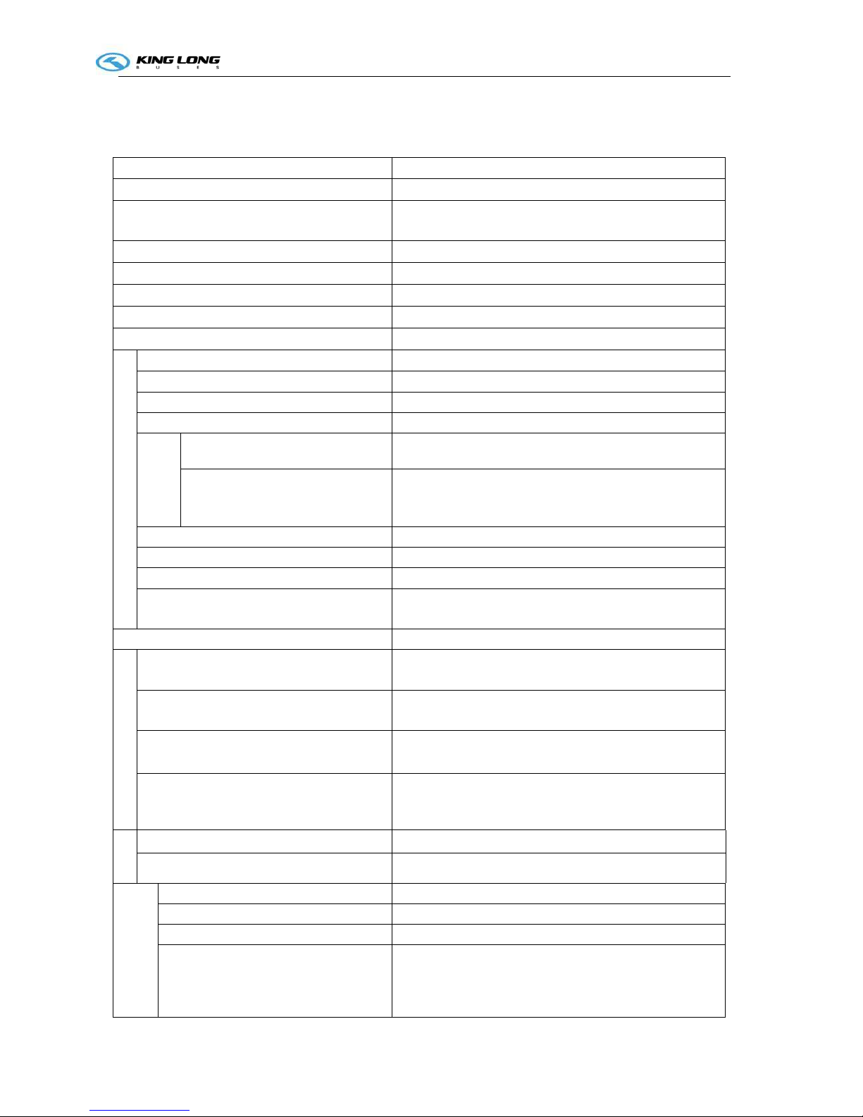
Technical parameters of the complete vehicle
(Vehicle No:D2900633)
Product Model XMQ6900
Engine model
ISB6.7E5 250
Engine type In-line six-cylinder ,water-cooling four stroke direct-injection,
electronically controlling, diesel engine
Cylinder diameter × stroke (mm)
107×124
Displacement (mL)
6700
Compression ratio
17.3:1
Rated capacity / rotation speed Kw/r/min
184/2500
Max. torque / rotation speed N.m/r/min
950/1200
Dimensions
Overall length (mm) 8995
Overall width (mm) 2480
Overall height (mm) 3435
Wheelbase (mm) 4300
Wheel
track
Front mm) 2090
Rear (mm) 1860
Minimum lift-off clearance (mm) 230
Approach angle (°) 10
departure angle (°) 8
Front suspension / rear suspension
(mm)
1905/2790
Rated passenger (driver included) (person) ≤39
Mass parameter
Technically permissible maximum laden
mass(kg)
14000
Technically permissible maximum mass of
combination(kg)
17500
Technically permissible maximum laden
mass for front axle (kg)
4500
Technically permissible maximum laden
mass for rear axle (kg)
9500
wheel
Tire size (front, rear) 275/70 R22.5
Tire inflation pressure (kpa) 700
Performance
parameter
Max. speed (km/h) 115
Fuel consumption (L) --
Maximum gradeability (%) 30
Min. turning diameter (m) 17

Technical parameter and complete vehicle description
2-1
parking braking ability ( 20% gradient) parking for 5 minutes
Capacity data
Fuel tank(L) 200
Engine oil(L) 26.5
Transmission lubricant(L) 42(first oil fill);24(service oil change)
Main retarder lubricant(L) 11
Power steering hydraulic oil(L) 6~7
Clutch oil(L) 0
Technical parameter and complete vehicle description
2-2
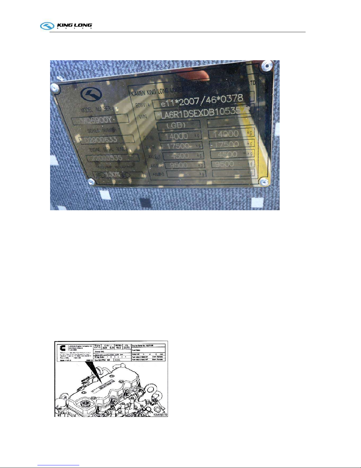
Introduction to data plate
Bus data plate
The bus data plate may be affixed to either the upside of the front passenger door frame or to the side of the
front passenger door step (the position may vary with vehicle model). There are many parameters on the
plate, such as vehicle model, gross mass, vehicle serial number, vehicle capacity, VIN (short for vehicle
identification number), chassis serial number, engine serial number, engine model, rated power, production
data and etc..
Chassis data plate
The chassis data plate with vehicle identification number (VIN) is upon the front door.
Engine data plate
The engine data plate is on top surface or salient top position of the engine, whose position may be
various according to different engine manufacturing plant.
The engine number is stamped on the left or right block of the engine, whose position may be various
according to different engine manufacturing plant.

Technical parameter and complete vehicle description
2-3
Product quality assurance
We insisted that the end user should make breaking-in maintenance of the rolling-out new vehicles in
their initial driving mileage of 5000 km. Users must make proper operation and maintenance strictly
according to relevant regulations in the instruction book. Please refer to “workshop manual” for product
quality assurance and abide by related specification.
Technical documents
The instruction book is used combined to the following specification:
Engine operation instruction or service manual
Note: the instruction book should be modified according to specific configuration of vehicle

Technical parameter and complete vehicle description
2-4
Body Structure
1. Structural style
Semi-integral body structure
2. Structure
The bodywork structure adopts closed girder construction of six major assembly parts, which are
combined welded by rectangle steel pipes with advantages of strong structural stiffness, torsion
resistance and bending resistance as well as relatively simple craftwork. Main components of skeleton
have been performed anticorrosion treatment to ensure steady adhesion of coating and strong capacity
of antirust and corrosion-proof.
3. Interior trim
The interior adopts flexible design and the floor adopts steel plate/wood block composite construction,
and covered with anti-slip and antifriction leather with favorable sound insulation value.
4. Windows
The front windshield is the hyperboloid triplex glass fixed by the gluing; the rear windshields is fixed
by harden glass, the side windows are sealing style, which are made of hollow glass. The driver’s
window is fixed with sliding window.
5. Baggage compartment
The baggage compartment adopts transverse run-through design, and they are all made of aluminum.
6. Seat
Driver’s seat: Q15-2 driver seat, adjustable seat with high backrest and three-point belt.
Passenger seats: KE-1 type seat, with foot pedal and transverse movement function, high backrest, the
all seats are equipped with three-points seat belt.
7. Interior accessory device
The vehicle is equipped with electronic clock, electric front windshield sunshade, driver side sunshade,
electric driver window, safety hammer, emergency escaping window, curtain and luxury bilateral H type
luggage rack,engine cabin fire extinguisher, electric mirrors, VDO travelling data recorder, reversal
monitor, middle door (located in front of the rear axle), icebox, front and middle flip LCD TV, DVD
player ,etc..
8. Air-conditioning system
Cooling system: WEBASTO top mounted dependent air-conditioning system..
Heating system: WEBASTO heating system. and NANFENG radiator system..
Defroster: NANFENG cooling /heating defrosting device
9. Door
The door adopts the full aluminum remote control out-swing pneumatic doors.
The out-swing door adopts the advanced electrically aerodynamic theory design, with the motion of
opening and closing placidly、agile、safe、lock credible and anti-clamp function.
A. Basic function
a. There are two electrically switches, the interior one is trigger touch-tone, which located on the
dashboard of the front right side of the driver, the outside one is a remote control switch. , both switches
can control the door.
b. When the circuit is in OFF position , the emergency switch can be used in the interior and
exterior ,the emergency switch of the door is located inwardly upon the entrance of the door and
outwardly behind the passenger door respectively, Please rotate the switch and throw open the door in
emergency.
c. Commonly the door is closed, when touch off any electrically switch, the door would move placidly
at a certain velocity, along with it, the step-lamp lights .when touch off the switch again , the door
would return placidly at a certain velocity, after the door returned , the step-lamp goes out.
Technical parameter and complete vehicle description
2-5
B. Hint:
a. The door remote control acts only when the parking brake is on the parking gear.
b. The door could only be opened when the external mechanical lock isn't locked up.
c. In order to avoid impact, make sure that the door is completed closed or opened, before you make the
next door switch operation.
Note: Deployment on the vehicle may be different with the above description because of different
deploying requirement of the clients.
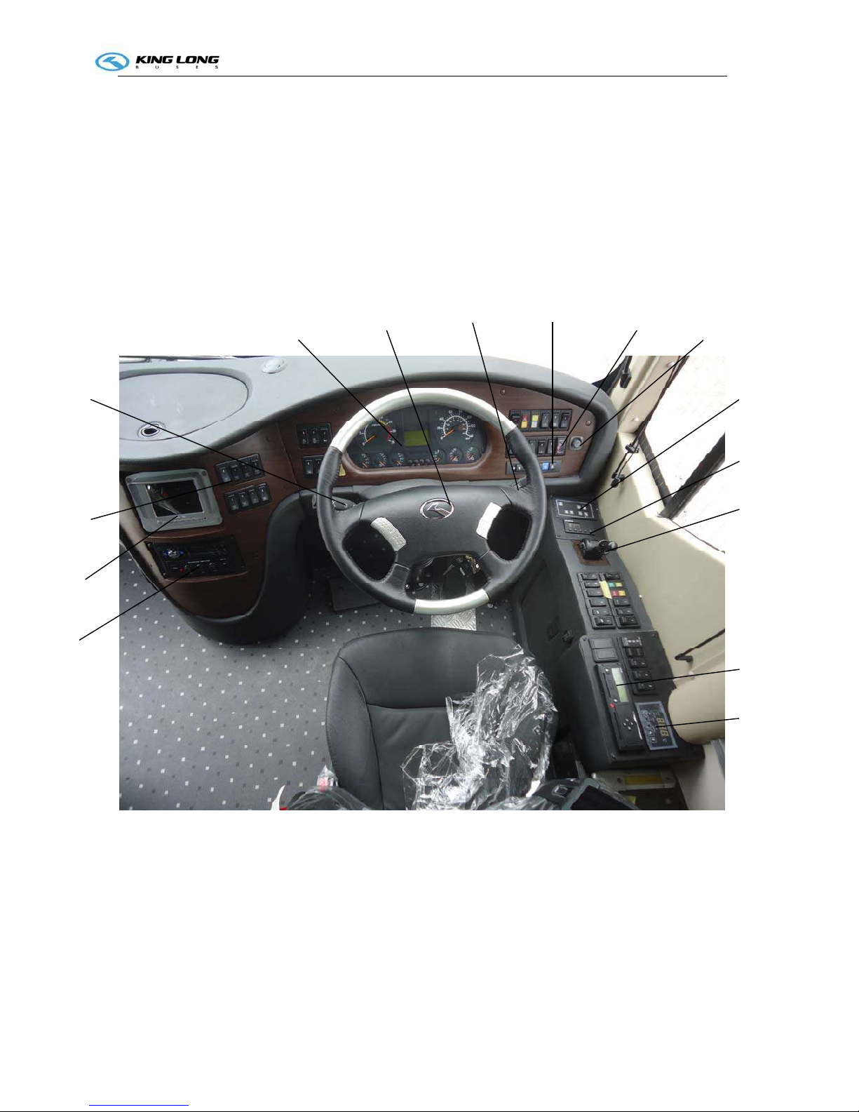
Schematic illustration of the driver zone
1 DVD/MP3 player
2 Reversal monitor
3 Rocker switch
4 Light control handle
5 Combination instrument panel
6 Steering wheel
7 Wiper control handle
8 Gearbox operation panel
9 Fire extinguisher pushbutton switch
10 Electric mirrors pushbutton
11 WEBASTO heating panel
12 WEBASTO heater timing panel
13 Parking brake handle
14 Travelling data recorder
15 Radiator operation panel
1
2
3
4
5
8 9
10
11
6
7
12
13
14
15
Operation Instruction
3-1
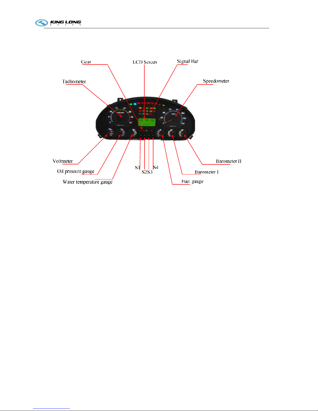
Instruction of instrument (VITI EDITION)
Figure-1 The Outline of ZB271M
The appearance of the ZB271M dashboard as shown in Figure-1 , it mainly contains eight indicator
type measuring instruments, 29 icons which were lighted by the light-emitting diodes, one LCD screen and
four buttons, dashboard pin definition go to Appendix A
2.1 Display Part.
1.Gear P—Brake gear, R—Reverse gear,N—Neutral gear,D—Drive gear,S—Safety belt.
2.Signal Bar. Go to Appendix B.
3.Speedometer .Display speed of car. Units :Km/h.
4.BarometerI and Barometer II. Display air pressure of car. Units: 0.1MPa .
5.Fuel gauge. Display amount of fuel. Units: Percentage.
6.Water temperature gauge .Display engine temperature of car. Units: ℃.
7.Oil pressure gauge. Display oil pressure gauge of car. Units : 0.1MPa.
8.Voltmeter .Display Voltage of car. Unit: V.
9.Tachometer .Display rotate speed of car. Units: r/min.
10.LCD Screen. Display interface information, engine information and so on. Go to Appendix C.
2.2 Button part
Operation Instruction
3-1
ZB271M dashboard has four buttons,S1、S2、S3、S4.
S1—Set Button. S2—Up Button. S3—Down Button. S4—Return Button.
S1 could set some information of dashboard, for example ,times, blacklight, VehPPK and so on.
S2 and S3 could flip the screen up or down.
S4 Return main interface.
Remarks: Do not press S1 when flip the screen up or down.
3 Instructions
3.1 LCD Display
3.1.1 After power on as shown in Figure-2: Total Mileage, Trip Mileage A and Trip Mileage B
Figure-2 Main interface
3.1.2The second interface display engine information,as shown in Figure -3。
Accumulated rotates and Engine running time.
Figure-3 Engine information
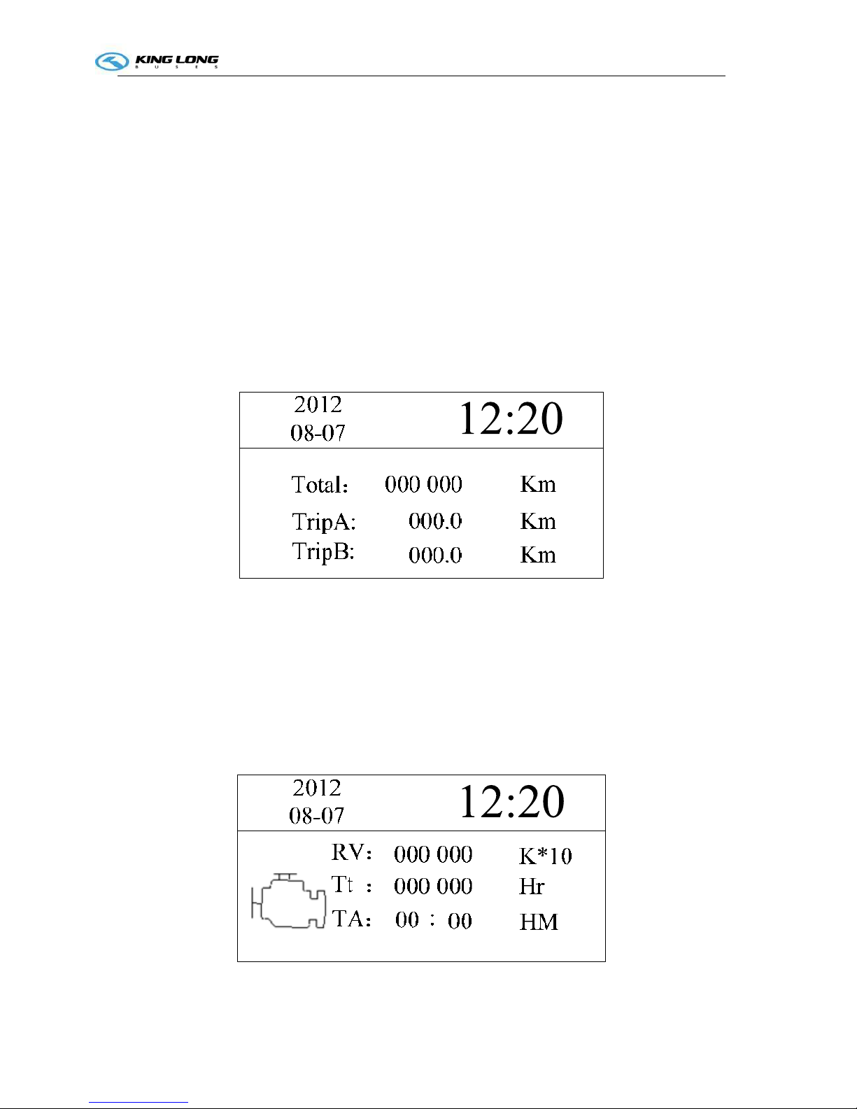
3.1.3 The third and the fourth interface display information of Fuel and Mileage as shown in Figure -4 and
Operation Instruction
3-1
Figure -5.
Figure-4 Fuel and Mileage information
2012
08-07
0000000000 .0 L
0000000000 .0 L
Figure-5 Fuel and Mileage information
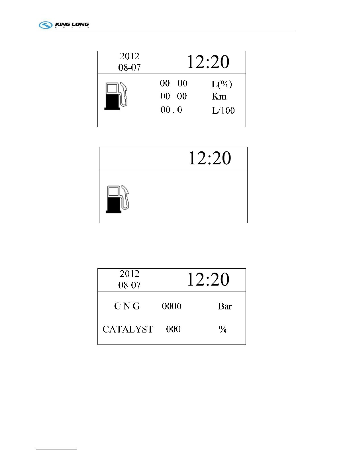
3.1.4 The fifth interface display CNG and Catalyst. as shown in Figure-6
Figure-6 CNG and CATALYST
3.1.5 The sixth display inside temperature,outside temperature and engine compartment temperature. as
shown in Figure-7
Operation Instruction
3-1
Figure-7 Car and Engine compartment temperature
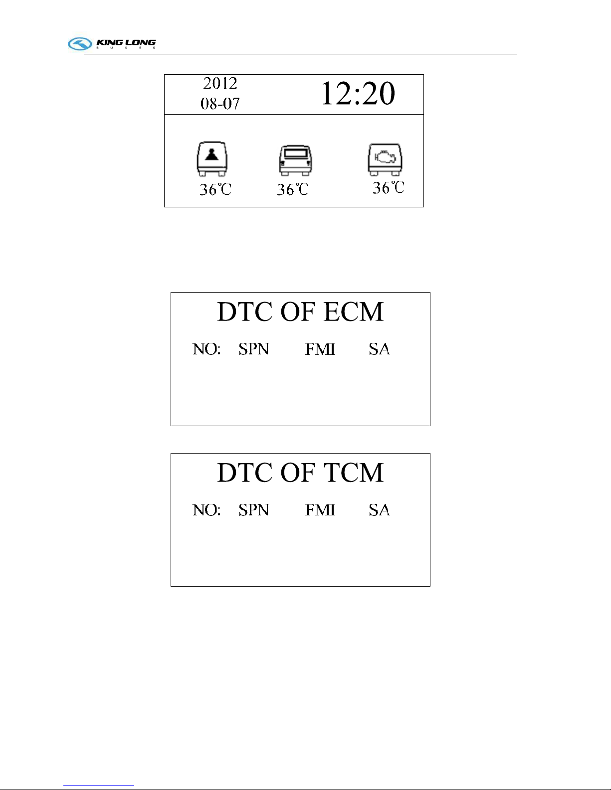
3.1.6 The seventh、eighth、ninth、tenth and eleventh interface display ECM、TCM、ABS、AIR、Retarded
information. as shown in Figure-8、9、10、11、12.
Figure-8 ECM Code
Figure-9 TCM Code
Operation Instruction
3-1
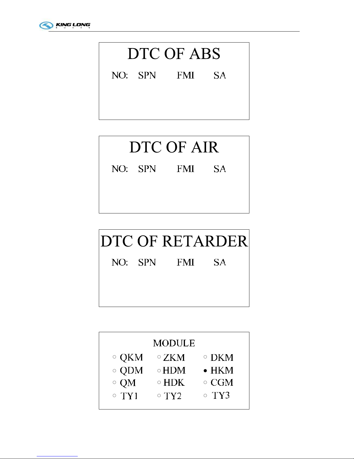
Figure-10 ABS Code
Figure-11 AIR Code
Figure-12 Retarded Code
3.1.7 The thirteenth interface display online module. as shown in Figure-13.
Operation Instruction
3-1
Figure-13 Online Module
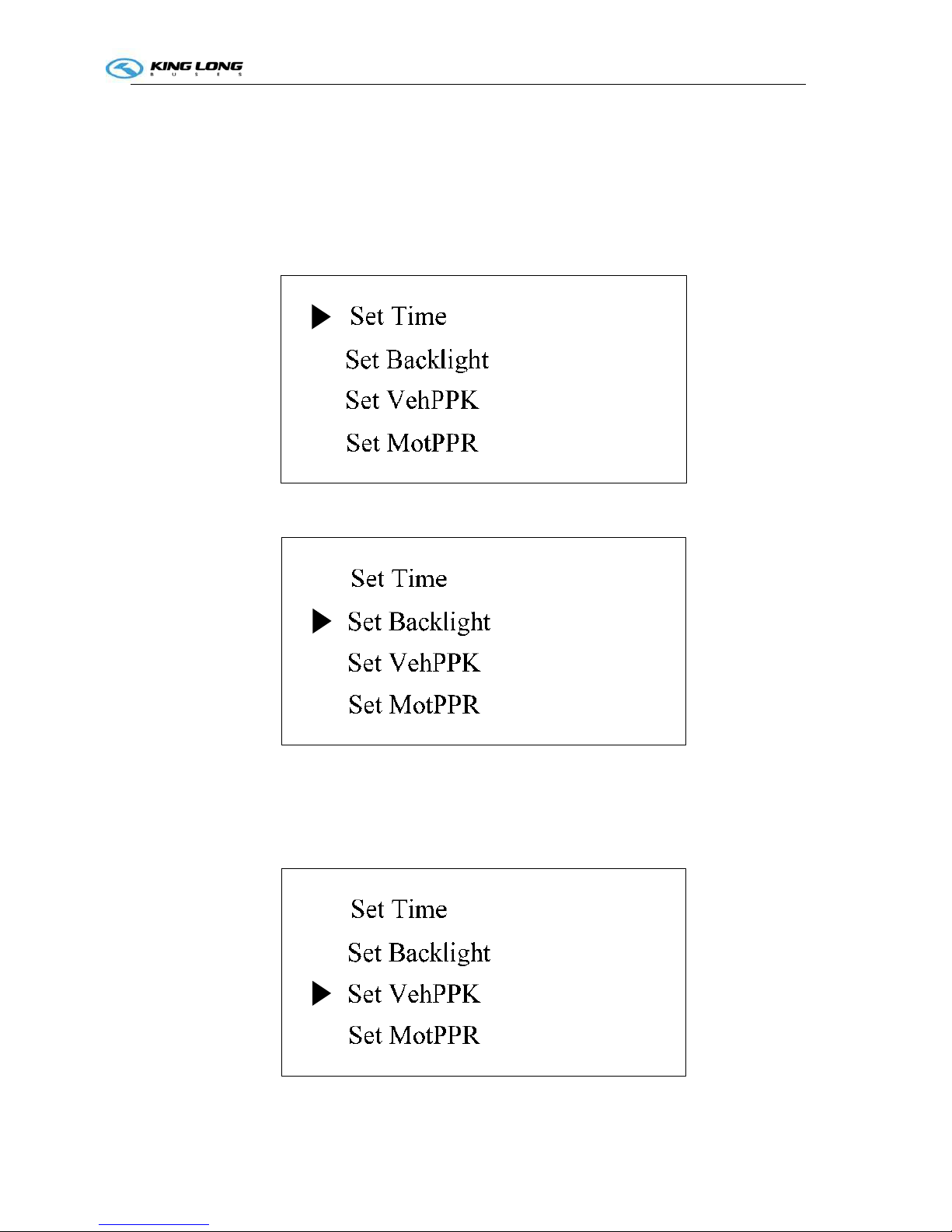
3.2 Dashboard Set
3.2.1 First,Press S1 go to set interface, Second, Press S2 and S3 flip the interface up or down.
Could Set Time、Set Backlight、Set VehPPK、Set MotPPR、Clear Trip A、Clear Trip B、ClearTA、
Clear Oneway OC. as shown in Figure-14、15、16、17、18、19、20、21
Figure-14 Set Time
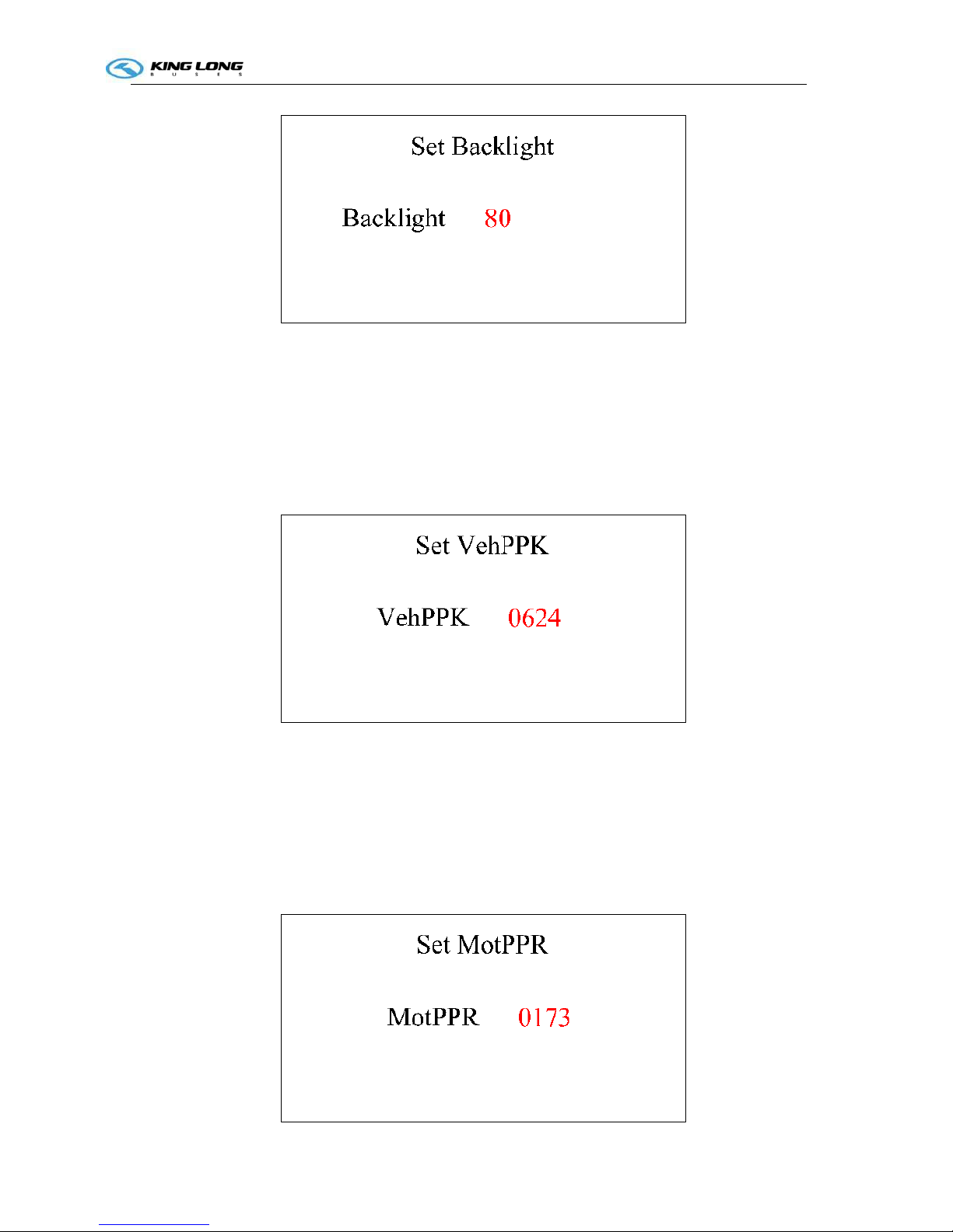
Figure-15 Set Backlight
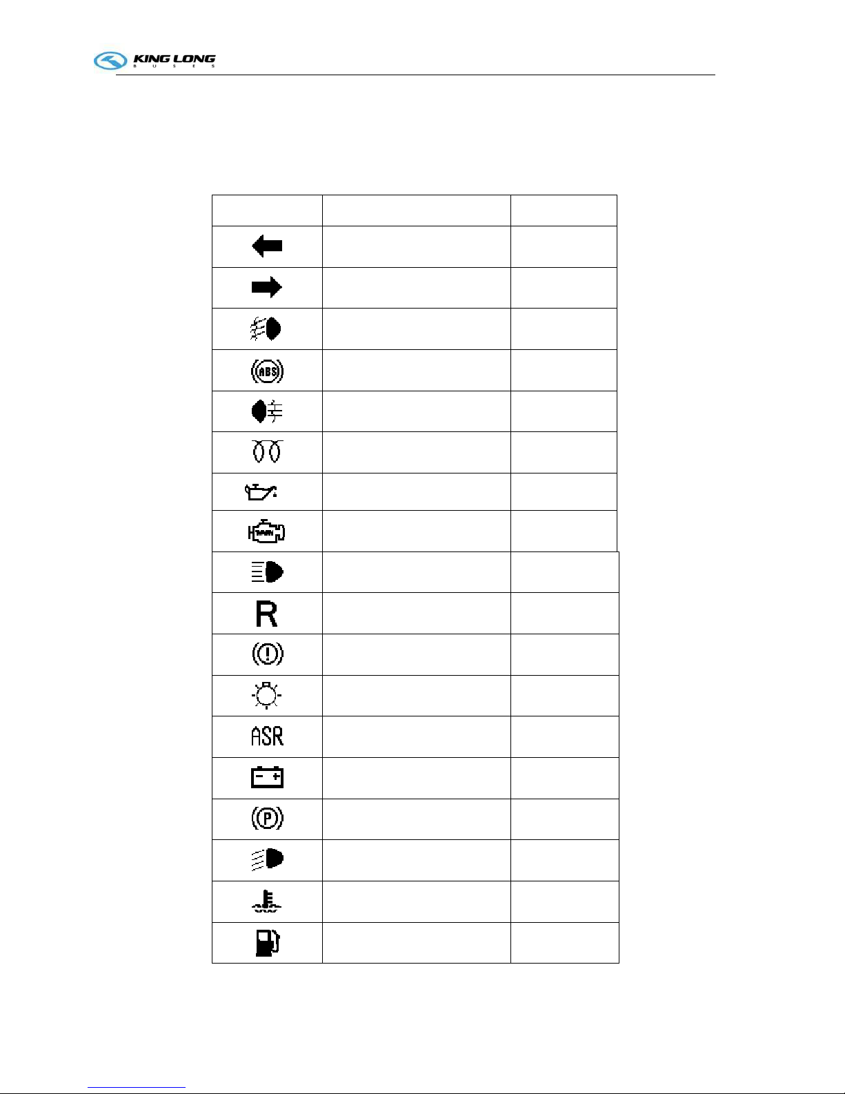
Figure-16 Set VehPPK
Operation Instruction
3-1
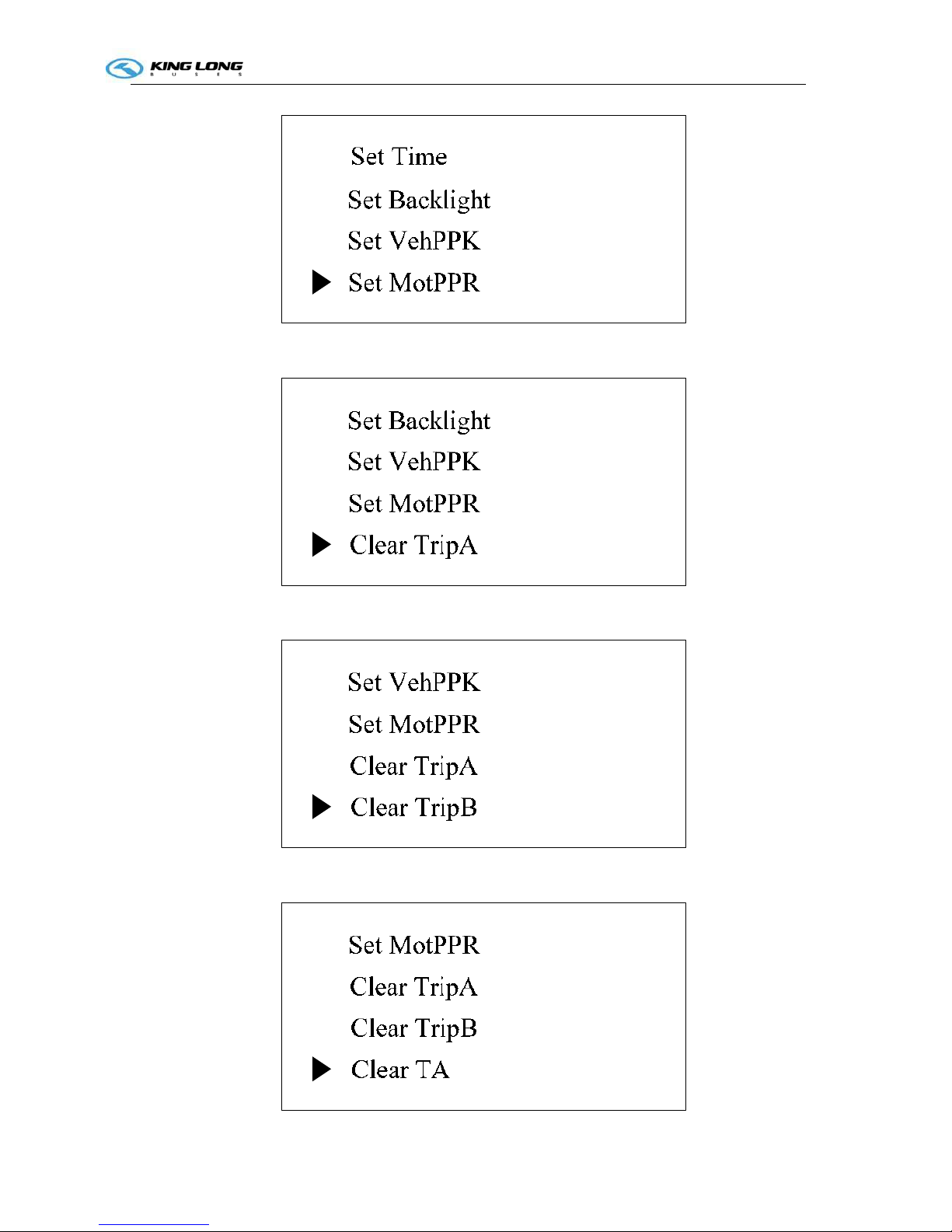
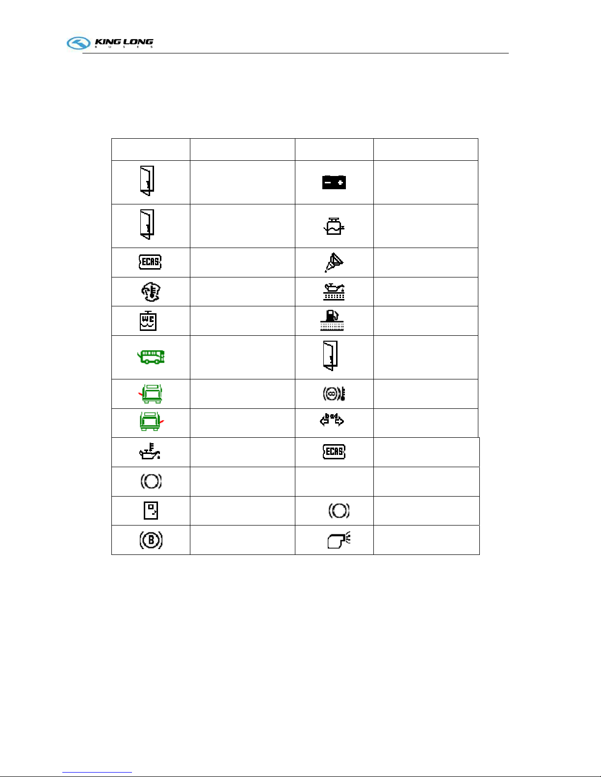
Figure-17 Set MotPPR
Figure-18 Clear Trip A
Figure-19 Clear Trip B
Operation Instruction
3-1
Figure-20 ClearTA
Figure-21 Clear Oneway OC
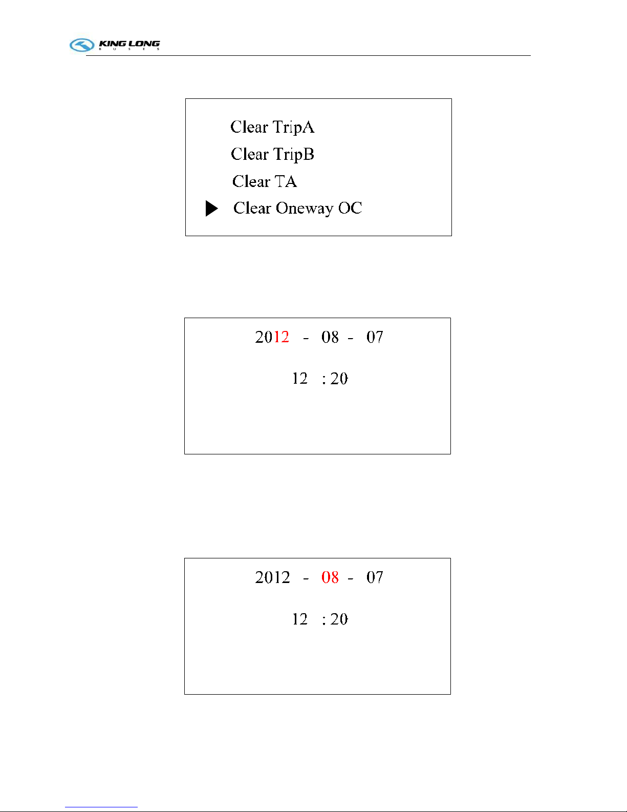
3.2.2 Set Time .First press S1 go to set interface, Second press S2 or S3 choose Set Time position as
shown in Figure-14, Third press S1 go to Figure-22.
Figure-22 Set Year
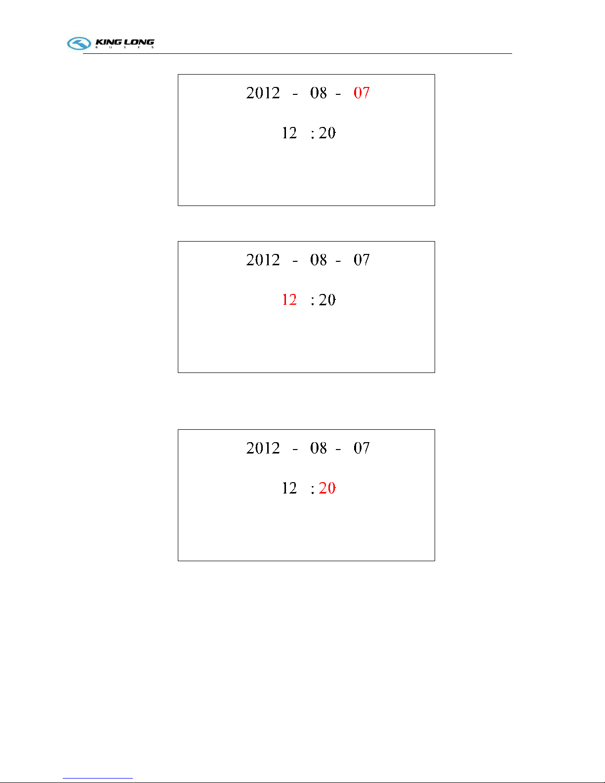
Finally press S2 and S3 could increase or decrease years. After set year, could press S1 choose Month、
Day、Hour、Minute as shown in Figure-23、24、25、26.And press S2 and S3 could set Month、Day、
Hour、Minute. After Set press S4 two times return main interface.
Figure-23 Set Month
Operation Instruction
3-1
Figure-24 Set Day
Figure-25 Set Hour
Figure-26 Set Minute
3.2.3 Set Backlight. First press S1 go to set interface, Second press S2 or S3 choose Set Backlight
position as shown in Figure-15, Third press S1 go to Figure-27.
Operation Instruction
3-1
Figure-27 Set Backlight
Finally press S2 and S3 could increase or decrease backlight. After set backlight, press S4 two times
return main interface.
3.2.4 Set VehPPK. First press S1 go to set interface, Second press S2 or S3 choose Set VehPPK position
as shown in Figure-16, Third press S1 go to Figure-28.
Figure-28 Set VehPPK
Finally press S2 and S3 could increase or decrease VehPPK. After set VehPPK, press S4 two times
return main interface.
3.2.5 Set MotPPR. First press S1 go to set interface, Second press S2 or S3 choose Set MotPPR
position as shown in Figure-17, Third press S1 go to Figure-29.

Operation Instruction
3-1
Figure-29 Set MotPPR
Finally press S2 and S3 could increase or decrease MotPPR. After set MotPPR, press S4 two times
return main interface.
3.2.6 Clear Trip A. First press S1 go to set interface, Second press S2 or S3 choose Clear Trip A
position as shown in Figure-18. Third press S1 clear Trip A and auto return main interface.
3.2.7 Clear Trip B. First press S1 go to set interface, Second press S2 or S3 choose Clear Trip B
position as shown in Figure-19. Third press S1 clear Trip B and auto return main interface.
3.2.8 Clear TA. First press S1 go to set interface, Second press S2 or S3 choose Clear TA position as
shown in Figure-20. Third press S1 clear TA and auto return main interface.
3.2.9 Clear One way OC. First press S1 go to set interface, Second press S2 or S3 choose Clear One
way OC position as shown in Figure-21. Third press S1 clear One way OC and auto return main interface.
Appendix A ZB271M Dashboard Pin Definition
Table A Pin Definition
Pin Name Color Remark
1 VPP Red
2 GND Black
3 WAKE_UP1 Red Connected to WAKE_UP2 inside
4 CANH1 Yellow Connected to CANH2 inside
5 CANH2 Yellow
6 CANL1 Green Connected to CANL2 inside
7 CANL2 Green
8 Empty
9 Empty
10 Empty
11 WAKE_UP2 Red
12 Empty
13 Empty
14 Empty
15 Empty
16 Empty
17 Empty
18 Empty
19 Empty
20 Empty
21 Empty
Operation Instruction
3-1
Appendix B ZB271M Signal Bar instructions
Icon Name Color
Left turn light Green
Right turn light Green
Front fog light Green
ABS Yellow
Rear fog light Yellow
Preheater Yellow
Alarm of oil pressure Red
Engine fault Yellow
High beam Blue
Return Red
Alarm of gas pressure Red
Clearance Lamp Green
Avoid side slide Red
Charge Red
Parking light Red
Low beam Green
Alarm of water temperature Red
Alarm of Fuel Low Red
Operation Instruction
3-1
Appendix C ZB271M LCD Alarm instructions
Icon Icon Name Icon Icon Name
Front Door
Low Power
Middle Door
Alarm of water level
ECAS Fault
Concentrate lubrication
Engine cabin
temperature too high
Alarm of oil filter
Lack water alarm of
W. C
Alarm of oil filter
Rear cabin door
Rear Door
Left cabin door
Alarm of Retarded
temperature
Right cabin door
Fault of turn light
Alarm of Oil
Temperature
Alarm of ECAS
Brake Light Fault CRUISE Cruise
Safety Door
Brake Light
Break Wear
Antifreeze controller
Operation Instruction
3-2
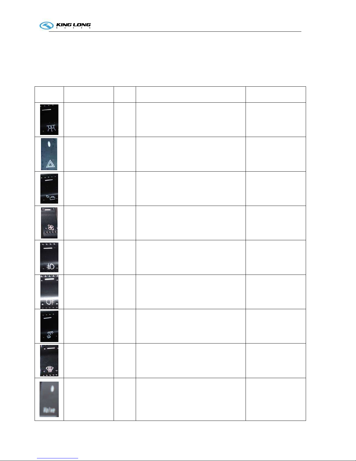
Illustration of switch and indicator
Number of switches , indicators and each own position may vary with the vehicle model and configuration
state, please refer to the flowing sheet :
Switch
Name Color Function Notes
Daylight lamp
White
Pressed on top: interior lighting OFF
Pressed on bottom: interior lighting ON
Hazard alarm lamp
White
Pressed on bottom: all turning indication
lamps will turn on and flash
Luggage
compartment lamp
White
Pressed on top: the luggage cabin lamp OFF
Pressed on bottom: the luggage cabin lamp
ON
Ventilator
White
Pressed on top: the ventilator is turned off
Pressed on bottom: the ventilator is turned
on
Front fog lamp
White
Pressed on top: the front fog lamp OFF
Pressed on bottom: the front fog lamp ON
Rear fog lamp
White
Pressed on top: the rear fog lamp OFF
Pressed on bottom: the rear fog lamp ON
Reading lamp
White
Pressed on top: the reading lamp OFF
Pressed on bottom: the reading lamp ON
Front windshield
defrosting switch
White
Pressed on top: turn off defrosting function
Pressed on bottom: turn on defrosting
function
Heating water
valve switch
White
Pressed on top: the valve is switched off
Pressed on bottom: the valve is switched on
Operation Instruction
3-2
Fresh air
ventilating switch
White
Pressed on top: the ventilation function is
switched off
Pressed on bottom: the ventilation function
is switched on
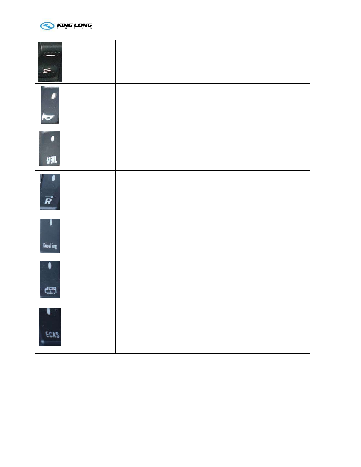
Horn
White
Pressed on top: the electric horn is turned off
Pressed on bottom: the electric horn is
turned on
Disinfection
function switch
White
Pressed on top: the function is switched off
Pressed on bottom: the function is switched
on
Reversal monitor
power switch
White
Pressed on top: turned off the monitor
power
Pressed on bottom: turned on the monitor
power
Body Kneeling
function switch
White
Pressed on top: turned on body restoration
function, the body start restoring action.
Pressed on bottom: turned on the body
kneeling function, the body start kneeling
action
Body
raise/descend
switch
White
Pressed on top: turned on the body
height adjust function, the body start raising
Pressed on bottom: turned on the
b
ody
height adjust function, the body start
descending
Body 2th height
adjusting switch
White
Pressed on top: the body height restore to
the normal height state from 2th height
location.
Pressed on bottom: turned on the
b
ody
height raise function, the body start raising
the 2th height location.
When driving in
rugged road, raise the
vehicle body height for
safe.
Operation Instruction
3-2
Switch Name Color Function Notes
Retarder
foot-control
function
release switch
White
Pressed on top: the retarder foot-control
function is turned on ;
Pressed on bottom: the retarder foot-control
function is turned off
Emergency
power switch
White
Pressed on top: turn off the vehicle
power
Pressed on bottom: turn on the vehicle
power
1) While only turn on
the switch, could
supply power only
for 2 minutes;
2) Meanwhile, if also
rotate the ignition
key to ACC or ON
shift, thus could
supply power for
long.
Front
windshield
sunshade
switch
White
Pressed on top: the sunshade will be raised
Pressed on bottom: the sunshade will be
descended down
Rearview
mirror
defrosting
switch
White
Pressed on top: turn off defrosting function;
Pressed on bottom: turn on the defrosting
function.
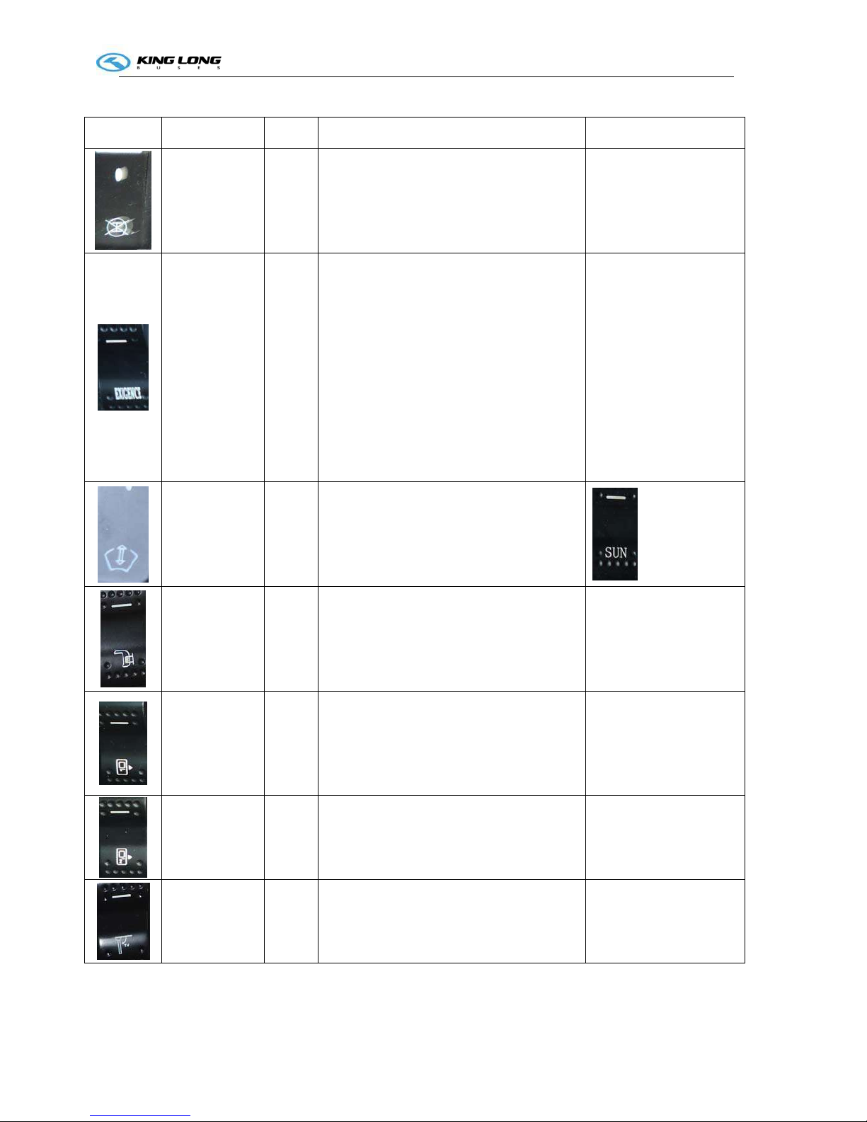
Front
passenger door
switch
White
Pressed on top: close the door
Pressed on bottom: open the door
Rear passenger
door switch
White
Pressed on top: close the door
Pressed on bottom: open the door
Flip TV switch
White
Pressed on top: turned off the power, folded
the TV
Pressed on bottom: turned on the power,
unfolded the TV
Operation Instruction
3-2
High/low shift
switch
White
Pressed on top: turned on the high shift
function
Pressed on bottom: turned on the low shift
function
Engine cabin
fire
extinguisher
switch
Red
Pressed down : extinguisher will be activated
The powder will be burst
out and coated on engine
cylinder block so as to
block up flame and
combustion. Don't test to
press this button down at
normal condition
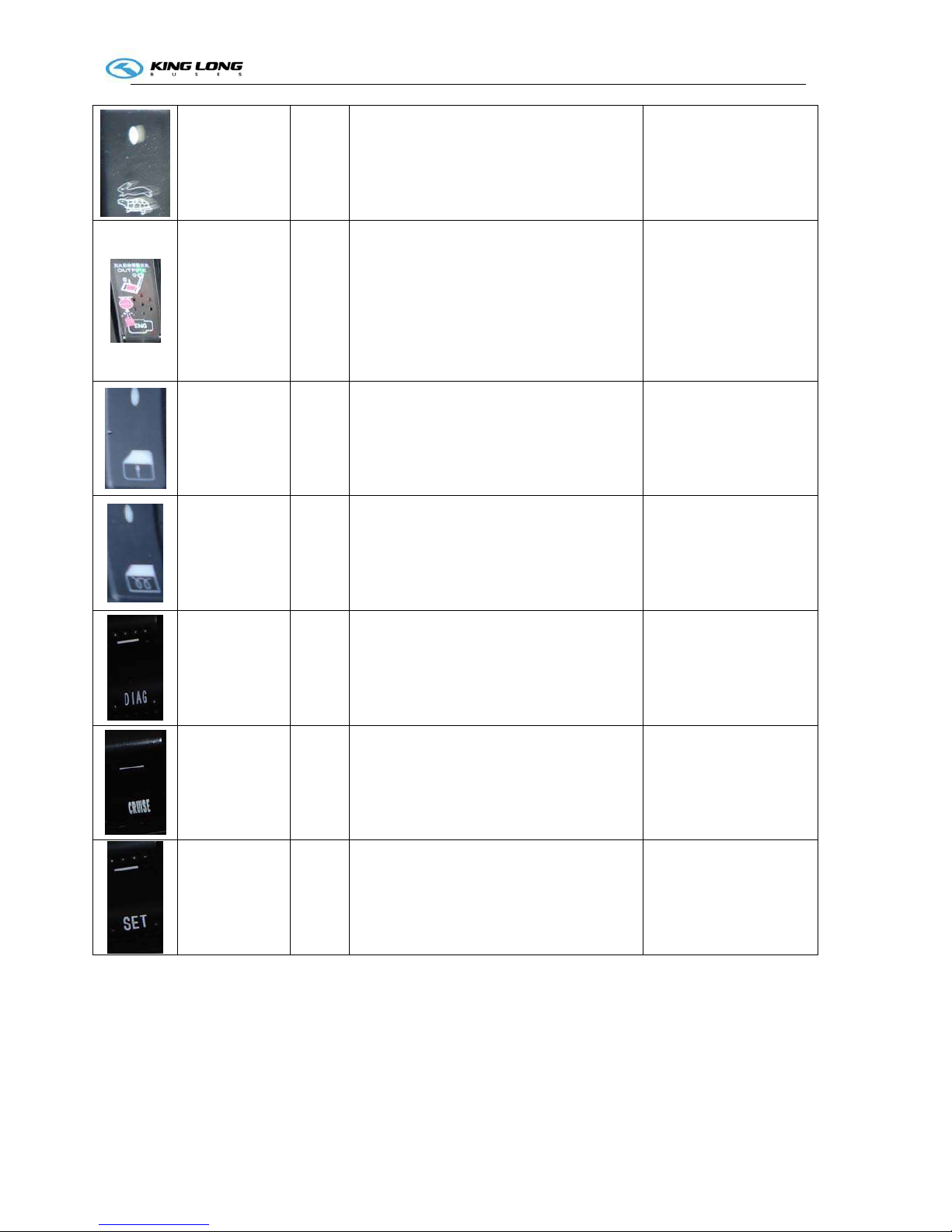
Driver window
raise/descend
switch
White
Pressed on top: turned on the raise function
Pressed on bottom: turned on the descend
function
Driver window
pre-heating &
defrosting
switch
White
Pressed on top: turned off the defrosting
function
Pressed on bottom: turned on the defrosting
function
Engine
Diagnose
function switch
White
Pressed on top: turned off the engine
diagnose function
Pressed on bottom: turned on the engine
diagnose function
Engine cruise
function switch
White
Pressed on top: turned off the engine cruise
function
Pressed on bottom: turned on the engine
cruise function
we advise clients not to
use this switch
Cruise set
switch
White
Pressed on top: turned off the engine cruise
set
Pressed on bottom: turned on the engine
cruise set
we advise clients not to
use this switch
Operation Instruction
3-2
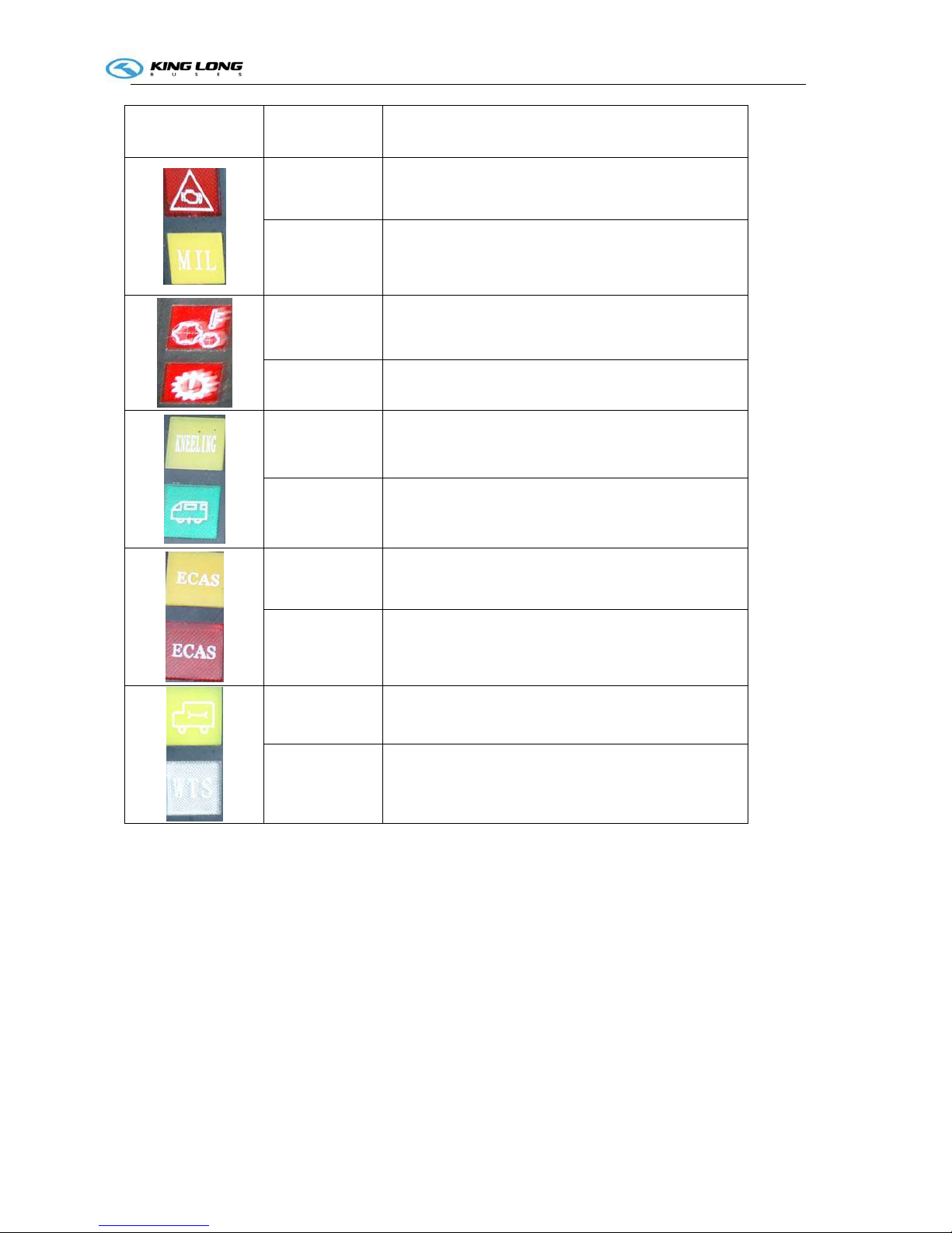
Indicator lamp
Color
Function
Red Engine fault alarm
Yellow Exceeding emission standard indication
Red Gearbox oil temperature over-heat alarm
Red Gearbox fault alarm
Yellow Kneeling function work indication
Green Body keep 2th height state indication
Yellow ECAS alarm indication
Red ECAS function fault alarm
Yellow Vehicle require maintenance indication
White Engine wait starting indication

Operation Instruction
3-3
CC350-355 series A/C Operation

Operation Instruction
3-3

Operation Instruction
3-3

Operation Instruction
3-3

Operation Instruction
3-3

Operation Instruction
3-3
Pre-heater Operation (Webasto)
1. General
The standard digital timer enables you to preset the
start of the heater operation up to 7 days in
advance.
It is possible to program 3 different starting times,
only one of which can be activated.
The standard digital timer features a wakeup alarm
function.
When the ignition switched on, the timer displays
the current time and the day of the week.
When the heater is switched on, the display and
the buttons are illuminated.
After the power supply has been connected,
all symbols on the display will flash.
The current time and weekday must be set.
2. Operation
The timer can be operated in that all flashing symbols
can be adjusted by means of the 10 and 9 buttons.
If the buttons are not pressed within 5 seconds,
the time displayed will be stored.
If the 10 and 9 buttons are pressed for more than
2 seconds, the fast time-setting mode is activated.
If the ignition is switched off while the heater is operating in the continuous mode, the
remaining operating time of 15 minutes is displayed and the heater continues to operate for this
period of time.
3. Switch the heater on
Manually: by pressing the button 8 (continuous heating mode)
Automatically: by programming the heater starting time
4. Switch the heater off
Manually: by pressing the button 8
Automatically: after the programmed operating time has elapsed.
With the heater running: by programming the remaining operating time
5. Setting time/day of the week
Press the 6 button for more than 2 seconds-time of the day if flashing-and set the clock using
the 9 and 10 buttons. Day of the week is flashing – adjust the day of the week.
6. Viewing the time
With the ignition switched off: press the 6 button.
7. Programming heater starting time:
Standard Timer
1. heater “on” indicator
2. day of the week
3.
time display
4.
memory location
5.
alarm indicator
6.
time
7.
program selection
8.
instant heating
9.
reverse
10.
forward
11. panel

Operation Instruction
3-3
Press the 7 button – the memory location is flashing – using the 9 and 10 buttons set start of the
heater operating time. Day of the week is flashing- set the day of the week. By repeatedly
pressing the 6 button, memory locations 2 and 3 can be programmed or the time display mode
can be reached.
8. Recalling/erasing preset times
Repeatedly press the 6 button until the desired memory location is displayed. To erase the
preset time, press the 7 button several times until the time of the day is displayed instead of the
memory.
9. Programming duration of operating time The heater must be switched off. Press the 9
button for 3 seconds – operating time is flashing – and set the desired operating time (10 to 120
minutes) using the 9 and 10 buttons.
10. Setting the remaining operating time
Set the desired remaining operating time (1 to 120 minutes) using the 9 and 10 buttons. The
remaining operating time refers to the time the heater still continues to remain in operation and
the ignition switched off.
11. Setting the wakeup time
A wakeup time can only be programmed on the standard digital timer. The wakeup time is not
bound to a specific day of the week.
Repeatedly press the 7 button until the bell symbol appears on the display. Set the
desired wakeup time using the 9 and 10 buttons. The alarm clock turns off after 5 minutes or
when one of the buttons is pressed.
12. Recalling/erasing the wakeup time
Repeatedly press the 7 button until the bell symbol appears on the display – read off
wakeup time. To erase the wakeup time: press the 7 button until the bell symbol is no
longer visible on the display.
13. remote control
Possible by means of an optional external “instant heating” button
14. Vehicles with ADR equipment
On ADR vehicles it is not possible to program a preset starting time. The remaining time is
shown on the display while the heater is in operation. The clock can be set. The alarm clock
function can be programmed on the standard digital timer.

Operation Instruction
3-3
NANFENG Panel Operation Description:
1. Heating panel power switch: while pressing the button 1, the panel lamps are turning on
or turning off, meanwhile, the heating opened or closed.
2. MANUAL/AUTO mode setting : while pressing on the button 2, may change over different
mode state, once in AUTO mode, the water valve would open automatically and keep
heating for room as far as the room temperature is below the temperature value which the
system was already pre-established in advance; once in MANUAL mode, the WATER
VALVE lamp lit on, the water valve keep opening all the time..
3. Temperature setting : In MANUAL mode state, if intend to adjust the room temperature,
may press button 4 or button 5 until your desirable temperature value, but your operation
should be pressed on the button 3 simultaneously.
1 2 3 4 5

Operation Instruction
3-4
Gearbox Operation
Transmission model (Automatic gearbox ZF 6AP1200B)
Variant with 3 push buttons, horizontally arranged(details may be different from illustration)
Fig.1
Fig.2
Operation Instruction ( as per Fig.1 or Fig.2 panels)
1.1 Push-button control with diagnostics connector
1.1.1 Variants
1.2
1.1.2 Push-button illumination

Operation Instruction
3-4
control unit(for potential cases see Section 1.3and 1.4)
1.1.3 Push-button selector position
1.2 Driving range
(see Section 1.1),consult the vehicle operation instructions

Operation Instruction
3-4
1.3 Starting the engine
Starts(see Section 1.1.2)and the transmission will remain
Have to be depressed and subsequently(see Section.1.4)
1.4 Engaging a gear
1.4.1 Standard

Operation Instruction
3-4
cases, the pushbutton depressed will flash (see Section 1.1.2)
1.4.2 Transmission with additional functions
1.4.2.1 Additional function “ Gear Release”
Procedure as described under 1.4.1. In addition to the
cases mentioned under 1.4.1, engagement of a starting
will flash (see Section 1.1.2)
1.4.2.2 Additional function“ Additional pushbutton reverse gear”
1.4.1
1.4.1
(see Section 1.1.2)
1.5 Starting

Operation Instruction
3-4
1.6 Downhill driving
1.7 Change in direction of travel
. Continue as described under Section 1.4
1.8 Kickdown (forced downshift)

Operation Instruction
3-4
1.9 Retarder operation

Operation Instruction
3-4
Section 1.1.2
1.10 Stopping, parking

Operation Instruction
3-4
1.11 Towing
1.11.1 Towing vehicle with coaxial transmission
1.11.1.1 Transmission is functioning

Operation Instruction
3-4
1.11.1.2 Transmission damage suspected
1.11.2 Towing vehicle with angle drive transmission
1.12 Temperature monitoring

Operation Instruction
3-4
1.13 Status monitoring/warning lamps
selector will flash (see Section 1.1.2)
1.14 Transmission response to a malfunction
(see Section 1.14.1)

Operation Instruction
3-4
1.14.1 Emergency operation

Operation Instruction
3-5
WABCO ABS BASIC INTRODUCTION

Operation Instruction
3-5

Operation Instruction
3-5

Operation Instruction
3-5

Operation Instruction
3-5

Operation Instruction
3-6
ECAS System Introduction (for tourist bus use)
1. System introduction

Operation Instruction
3-6
3. System function

Operation Instruction
3-6

Operation Instruction
3-7
Open/close the passenger door.
1. Before leaving the vehicle, press the button 1 of the door remote controller
to close the door.
2. Use the key to lock the door. First insert key into
the hole 3 and clockwise rotate key about 90°,
then anticlockwise rotate handle 4, after that the
door would be locked.
3. If need open the passage door, insert key into the
hole 3 and clockwise rotate it about 90°, then
clockwise rotate handle 4, follow press the button
2, after that the door would be opened.
Appendix:
The following are all type of door lock and door remote controller of King-Long.
1
3
4
2
Lock1
Lock 2
Lock 3
1
2

Operation Instruction
3-8
Door emergency switch
The model 1 door emergency switch is located on right upside
of the ingress.
The model 2 door emergency switch is located on right
underside of the ingress
The model 3 door emergency switch is located inside the door
pump cover which is on the top of the door.
Please rotate the switch and throw open the door in
emergency.
Special attention: The door emergency switch is only used
in the emergency mode. Please don't rotate the door
emergency switch in driving for fear of danger.
Door remote controller 2
Door remote controller 1
Model 1
Model 2
Model 3

Operation Instruction
3-9
Adjustment of the driver's seat
The driver's seat may be made proper adjustment for the
back and forth as well as the backrest angle according to
requirement of the driver.
Handle 1 and Handle 2: cushion height adjustment
Handle 4: back and forth adjustment
Handle 3: adjustment of the driver’s weight
Left handle: backrest angle adjustment
Note: Number of handles varies with vehicle model
Attention!
The seat should not be adjusted during driving
to ensure driving safety.
Adjust the driver seat only when the vehicle is stopped
and the parking brake is on.
1
2
3
4

Operation Instruction
3-10
Horn button
It is on the steering wheel. The horn is hooting when
pressing the button 1.
The type of steering wheel may vary with vehicle model.
Please use the horn only when strictly necessary to warn
other drivers and pedestrians.
Model 1
Model 2
1
1

Operation Instruction
3-11
Adjustment of the steering wheel
Pull-up the loosening handle 1 or rotate the loosening button
2. Adjust the height and the inclination of the steering wheel
to the desired position. After adjusting, press the regulating
handle or button down to lock the steering column.
Note: Number of handles varies with vehicle model
Attention!
Adjust the steering wheel only when the vehicle is stopped
and the parking brake is on.
After adjusting, press the regulating handle or button down
in order to lock the steering column.
1
2

Operation Instruction
3-12
Ignition switch
Position of the ignition key is shown in fig.1.
1."L" LOCK: Insert or remove the key in this position.
2."A" ACC: Power supply of the instrument is switched on
3."O" ON: Normal driving position
4."S" START: Initiating position of the engine, and the key
may rebound to the "ON" position automatically after the
startup
.
Before starting the engine, turn the key to the “ACC”
position and then to the “ON” position. At this point, three
lights (red, yellow and green) on the dashboard will come on.
Wait for the lights to go out completely before you start the
engine. However, make sure that all of the self-check lights
have gone out completely before starting the engine. Allow
the engine to run at idle speed for three to five minutes after
it has been started; but never let it run for more than 10
minutes at idle speed. If the vehicle does not move, increase
the fuel to the accelerator modestly to increase the rotational
speed of the engine a little; this will also prevent the early
wear and tear of the engine.
Note:
1. Turn the ignition key to the OFF position after the engine has been turned off and has stopped
running.
2. If the first attempt to start the engine is not successful, please wait two minutes before trying again.
3. If the engine fails to start after three attempts, check the fuel supply system. If the vehicle runs on
natural gas, check the gas supply system.
Attention!
1. Do not remove the ignition key while the vehicle is in movement. And the ignition key should be
turned to the LOCK position only after the engine shut down.
2. When leaving the vehicle, even for a short period, take the key out to avoid operation of the vehicle
by children or unauthorized persons.
1

Operation Instruction
3-13
Lamplight operating handles
The lamplight operating handle is located on left
underside of the steering wheel, which control the front
small light, headlamp, headlamp dimming, etc
OFF Indicating that the headlamp and the small
lamp are all off.
Is the small lamp indication. The small lamp,
the instrument light and the side indicator lamp will all
be turned on when anti-clockwise rotating the handle to
position of this identification.
Is the Is the headlamp indication. The headlamp,
small lamp, meter lamp and width lamp will all be
turned on when continuously anti-clockwise rotating the handle to position of this identification.
Is the turning indication. By up and down motions of the operating handle may control the
left and right turning lamp and that on the dashboard.
Is dimming indication. Back and forth the operating handle gently may actuate the headlamp
dimming.
Note:
It’s important to dip the lights promptly when approaching an upcoming vehicle in order to avoid
dazzling its driver with the high beam of the headlight.
Model 1
Model 2

Operation Instruction
3-14
Wiper operating handle
The wiper operating handle is located on right underside
of the steering wheel. (model 1~2)
OFF Out of work
INT interval wiper operation step
LO Slow wiping
HI Quick wiping
The wiper may spray water by pressing the end of the
handle.
The shifts of the retarder may be converted by up and
down motion of the handle.
Note: do not actuate the wiper without water; press the
washer button as needed, then actuate the wiper.
Model 1 (with retarder)
Model 2 (with exhaust brake)

Operation Instruction
3-16
Passenger control panel instruction
1. air outlet
2. service button
3. reading lamp button
4. lamp
5. loudhailer
6. stop button
Model 1
6 1 2 5 4
1 2 3 4
Model 2
5 4 2 1 3
Model 3

Operation Instruction
3-17
Safety hatch
The safety hatch is located on scaffold of the vehicle.
Please open the safety hatch according to the above
diagrammatic representation and illustration for
escaping in case of danger.
When in emergency and dangerous condition, should
1) push upward with hands and make the hatch open
2) pull down the plastic cover and rotate red handle
3) push dome open
4) exit through hatch
Model 1
Model 3
Model 4
Model 2

Operation Instruction
3-18
Safety hammer
The safety hammer is located on the side window.
Please take down the safety hammer and break open
the safety window for escaping in case of danger.
Model 1
Model 2
Model 3

Operation Instruction
3-19
Relays & Fuses
The Relays & Fuses Box always installed in the
compartment of the instrument desk or a tool cabin belong
to front right side panel.
The box integrates 50 chip-type fuses, 20 general and
special relays, and has 8 standby chip type fuses, one fuse
clip, which makes its construction more compact and
function more powerful. It improves design of the past
Relays & Fuses Box , therefore it avoids weakness such as
unreliability and short service life, it applies integrated
circuit and designs 5 special relays: intermittent wiper
relay, turning flasher relay, lower water level warning
controller relay, monitor power relay, brake light failure
warning relay (when power supply voltage is lower than
23V, power supply of acoustic set and monitor is cut off
and will be begin to work again after power supply voltage resumes to normal)
.
The vehicle installed the Relays & Fuses Box in the compartment of instrument desk.
Installation Position
The position of Management Module,
CAN Processor Module, and the
Relays & Fuses Box
They are located in the compartment of
instrument desk. When servicing, may open the
desk cabin gate

Operation Instruction
3-20
Switch control box (Model: CQ2025)
CQ2025 A wiring diagram (Printed on opposite cover of the switch control box)

Vehicle Starting and Driving
4-1
Preparative for vehicle operation start up:
Check daily, before turning engine on:
1. Check oil level of the engine
The warning “Engine oil pressure” is displayed as a signal
item on the combination instrument when the oil pressure
is too low, the alarm buzzer sounds, the warning light
STOP comes on, stop the engine and check engine oil level
at the dipstick. Provide immediately for the oil
replenishment to its correct level.
The oil level should always be checked with the vehicle
parked on level ground, before starting the engine up, or at
least 5 minutes after having shut it down.
Open the engine compartment hood.
Take out the oil dipstick, and clean it with a clean cloth
without loose threads, and put it back into its place fitting it
in completely.
Once again pull out the dipstick and check the oil level.
a. The oil should not exceed the maximum level.. drain
the excess.
b. If the oil is at operational level, do not add more oil to
the crankcase.
c. If the oil is at or below the minimum level, add the
same type and brand of oil to the crankcase as that
already there, until reaching the maximum level..
After the checking, replace and fit the dipstick completely
back into its place.
If the oil level is checked after the engine has been run for
a period of time, then it should take at least five minutes
before the measure to ensure the oil back flow to the oil
sump in full.
Oil level dipstick
Oil inlet

Vehicle Starting and Driving
4-2
2 Check level of the coolant
The coolant level is automatically monitored.
If coolant level gets too low,the digital indicator
displays a driver information on the combination
instrument. In this case, park vehicle in a safe place as
traffic conditions permit, stop engine and visually
check the coolant level.
Check the coolant level only when the engine doesn’t
work and its temperature is below 50℃.
The anti-freezing rust-inhibiting engine coolant level
can be observed from the observe pipe.
The coolant level should be between the maximum
level (MAX.) and minimum (MIN.) level indicators in
the compensation tank.
If it is necessary to add coolant to the system:
a. Place the heating system command in the position
of maximum heating potency.
b. Add the coolant to the system up until the
maximum level indication. Only use coolant
which is recommended.
c. The compensation tank cover should not be
opened when temperature of the coolant is still
high to avoid being scalded Place the lid on the
system and turn it to the limit.
d. Pressure valve of the compensation tank should be
opened when adding the coolant to eliminate air in
coolant pipeline of the diesel engine.
e. Run the engine for a short time at varied rotations.
f. Stop the engine and check the coolant level.
If necessary add more coolant to the system
Anti-freeze and antirust solution (mixture of glycol and water) should be added to cooling system from
time to time to avoid sediment, frost, oxidation and increase boiling point.
Note: When adding coolant, please choose the same model to avoid sediment. If coolant is degenerative,
replace it immediately.
Coolant specification as shown below: users should choose products produced by normal factories
according to requirement
Observe pipe
Observe pipe

Vehicle Starting and Driving
4-3
3 Fuel pre-filter with water separator (drain accumulated water)
Draining accumulated water
On a daily basis, check the lower cup of the water separator. If there is water in the cup, unscrew the
draining plug one or two turns, to drain the accumulated water.
After draining the water, tighten the draining plug correctly.
When the accumulation of impurities in the lower cup is noticed, take the vehicle to a workshop to carry
out its cleaning.
Changing the fuel pre-filtering element
The fuel filtering element should be changed periodically,
at the intervals recommended in the maintenance manual.
If however, the filtering element is easily saturated
needing substitution at very short intervals, this is an
indication of the accumulation of impurities in the
interior of the fuel tank, and the cleaning of the latter
should be carried out.
In order to change the fuel filter element, take the
vehicle to a Dealer or a King-Long Workshop.
Fuel system discharge
Activate the manual pump until feeling resistance on
pumping.
Start up the engine without accelerating. If the engine
does not start running in 20 seconds, interrupt the startup
and wait at least one minute before trying again.
If the engine insists on not working, repeat the discharge
operation.
Leave the engine running for about a minute to
completely eliminate the air from the system by way of
the auto-discharge system.
In order to reduce environment pollution problems, do
not drain the residues accumulated in the water separator
directly into Nature (rivers, lakes or soil). The drained
residues should be collected in appropriate containers
and taken to receiving centers to have proper final
destination (see local legislation).
Model for Euro III IV
Manual pump
Release valve

Vehicle Starting and Driving
4-4
4. Fuel level
Turn the ignition key to drive position (on).
Check the fuel level on the indicator. If necessary, fill up
the fuel tank.
(But direct viewing by open the tank cover is
preferred).
Eliminate deposite water in diesel filter in time and check
fuel pipe for no leakage. Ensure sealing performance of fuel
tank , and wipe up dirt before opening fuel tank.
Before filling up, shut down engine.
Do not drive vehicle in empty fuel tank. When the fuel
level indicator is on the red bar, refuel the vehicle to avoid
air entering the fuel system.
Fill the fuel tank only with good quality fuel free of
contaminants.
The fuel might as well be filled up when
running in the humid area to avoid inner rustiness.

Vehicle Starting and Driving
4-5
5. Vehicle lighting, intermittent lights and brake lights
Check all instruments and indicator lamps for normal, especially the head lamp, the turning lamp, the brake
lamp, the reversing lamp and the danger alarm lamp.
Check the bulb and the switch for their damage. To carry out the lamp substitution, hands should be very
clean. If possible handle new lamps with tissue paper.
Clean the external of all instruments and indicator lamps to ensure clear indication.
Attention!
The traffic laws regulate the location, lighting intensity, and color of the lenses and the quantity of
lanterns for each type of vehicle. The King-Long vehicles leave the factory in strict obeyance of these
specifications. Traffic safety depends on these factors; therefore do not change the place of the lanterns.
Substitute the damaged lanterns only for other original ones. Remember that a change of lantern colors
can confuse other motorists and result in serious accidents. Avoid unnecessary lantern adaptations.
When substituting lamps, use the same type and potency as the original lamps. Do not carry out any
lamp adaptation in the headlights, as this will affect their adjustment and performance, putting the
vehicle traffic safety at risk.
On a regular basis revise the illumination system, keeping it always in perfect working conditions

Vehicle Starting and Driving
4-6
6. Check the level of AdBlue and the daily maintenance of SCR system
(1) Check the level of AdBlue.
When the vehicle key rotate the ON position, the LED
screen of combination instrument will display the
remain volume of the AdBlue, please see the right
diagram.
The AdBlue consumption is 5 percent of the fuel
consumption. If the remain volume of AdBlue is less
than 12%, the lamp 1 will flash and you need add
AdBlue. If the remain volume of AdBlue is less than 6%,
this lamp will light and the power of engine will be
declined forcibly. This will cause the emission
substandard and it is not good to engine.
(2) The daily maintenance of SCR system
Please add the AdBlue when it is insufficiency. Ensure the AdBlue meet the requirement. Check the SCR
system is well enough and has no leaking before driving. There is obvious add mark in AdBlue tank. If
add substandard AdBlue, must stop the vehicle right now and clean the AdBlue tank, re-filling the
qualified AdBlue. The air filter should be clean and replace regularly.
Special attention:
1
The volume of AdBlue

Vehicle Starting and Driving
4-6
If the AdBlue spill in skin, mild irritation may occur. Wash off with soap and water. If the AdBlue spill in
eye, irrigate eyes with large amount of water. The AdBlue is Non-combustible, if heated water evaporates
and ammonia will be released.

Vehicle Starting and Driving
4-7
7. Drain water in air tank
Open the water drain valve of air tank to drain oily water fully. If too much oily water is bled, check to
see if desiccant needs to be replaced in air drier. (This may be avoided when adopting the automatic drain
valve but it should be checked every two weeks)

Vehicle Starting and Driving
4-8
Check daily after turning engine on:
1. engine oil pressure
Run the engine.
The information on engine oil pressure can be requested through the driver information digital display.
If the oil pressure is too low, the oil pressure is automatically shown on the combination instrument.
Indication of the oil gauge will show a high value after the cold start of the engine and then it should be
kept within the range of 0.07-0.52Mpa (0.7-5.2kg/cm
2
) along with the increment of the oil temperature as
well as the normal engine speed.

Vehicle Starting and Driving
4-9
2. Pneumatic pressure
The air pressure gauge indicates the reserve pressure individually for the front and rear service brake
circuits.
The reserve air pressure in each brake circuit must be sufficient for the correct operation of the brake
system.
The STOP warning light comes on in case of low brake pressure in the service brake circuits.
Attention!
If the driver information indicator displays the warning “brake pressure” and the STOP warning light
comes on with the engine running, it will be an indication that the air pressure is excessively low. Do not
drive the vehicle if the air pressure gauge displays low air pressure in one or both brake circuits, as the
service brake could fail to result in serious accident.

Vehicle Starting and Driving
4-10
3. Tachometer working order
Indications on tachometer scale:
a. Green zone – operating range of maximum
performance
b. Yellow zone – a little high speed range (warning of
engine overspeed )
c. Red zone – engine overspeed range (risk of
immediate engine damage)
Always observe tachometer while driving the vehicle.
Whenever possible keep engine running within the
economical range.(green zone)
On downgrade, select an adequate gearbox speed and monitor vehicle speed to avoid engine operating in
the danger range (red zone).
When the exhaust-brake is operating on down grades, select an adequate gearbox speed to keep engine
speed within efficient exhaust-brake operation (yellow zone).
Always avoid engine over revving (red zone), as engine operation in this speed range can give rise to a
immediate engine damage or seriously jeopardize its durability.
The yellow range with red reticle can be used occasionally when the exhaust-brake needs to be used at its
efficiency limit, however, at risk of engine durability. Therefore, do not operate in this range in a normal
or usual way.

Vehicle Starting and Driving
4-11
4. Steering play
Steering wheel play
Run the engine at idle gear and straighten the front
wheels forwards.
Turn the steering wheel alternatively to the right and to
the left.
The steering play (free movement of the steering wheel)
is measured on the perimeter of the steering wheel and
should be between 20 and 30 mm.
A

Vehicle Starting and Driving
4-12
Control periodically, at least once a week:
1. Check tire for abrasion and pressure and tire nut for fixture
The vehicle’s safety and performance depend considerably on the state of the tires, reason why they
should be checked daily.
Before driving a vehicle, check charging pressure of tire for normal, tire for damage, tire nut for fixture.
Note: At initial 50km, please tighten tire nuts of new vehicle to specified torque in appendix.
Tire pressure
Keep the tires always correctly calibrated. The inflation pressure should be checked with the tires cold at
least once a week.
After driving the vehicle for some time, the tires heat and in consequence of the heat, the inflation
pressure increases. Never, under any circumstance, empty heated tires to reestablish the recommended
inflation pressure.
The pressure difference between the assemble tires on the same axle should not be superior to 0.1 bar.
Wheel hubs
Keep them always clean, eliminating eventual mud or other dirt adherence. Substitute the damaged and/or
deformed hubs. The utilization of refurbished hubs is not recommended.
Wheel nut
Without fail re-tighten the wheel fastening nuts of new vehicles after running 50km.
The wheel fastening nuts should be retightened, crosswise, in turns, observing the recommended
tightening torque according to the type of fastening nut. If a torque meter is not available, tighten the nuts
strongly, using the vehicle tools without additional levers.

Vehicle Starting and Driving
4-13
2. Air cleaner (activate the dust discharge valve to loosen accumulated dust)
The maintenance of the air cleaner is made up of the
substitution of the filtering elements and should be
done only when the maintenance indicator indicates
the saturation of the element.
The cleaning of the main and safety filtering elements
is not recommended. The re-utilization of the filtering
elements can result in deficient filtering of the air and
cause serious damage to the engine.
When washing the engine, conveniently protect the air
inlet with a plastic or similar material to avoid the
infiltration of water to the air filtering element. After
washing the engine, remove the protection from the air
inlet.
Periodically press the dust discharge valve with your
hand, in order to incomplete the dust which possibly
be caught in the internal part maintaining them clear.
At the same time, check clip connecting rubber hose
of air intake system with steel tube in case of dust
entering air intake system due to looseness and
decrease in engine life.
The air cleaner restriction is electronically controlled.
If the indication of saturated air cleaner appears in the
display of digital indicator in combination instrument,
send the vehicle to a King-Long Dealer or authorized
workshop to inspect and clean the air intake system
and substitute the main filtering element.
Indication
The main filtering element of the air filter should be substitutes after maximum 2 years use.
The safety filtering element (optional) should be changed at every third main filtering element
substitution, or after maximum 2 years of use.
Model 1
Model II
1 automatic dust discharge valve

Vehicle Starting and Driving
4-14
3. General leakages (water, oil, fluids and fuel)
Check the engine, the transmission, the driving axle, the steering system, the cooling system and the oil
pipeline, the air pipeline of the complete vehicle for their leakage.

Vehicle Starting and Driving
4-15
4. Fastening and state of seat belts
Check buckle of the safety belt of the driver seat for normal and ensure for its lockup under the following
situations when fastening the safety belt.
● The body dashes forward all of a sudden;
● The vehicle makes an emergency braking or an abrupt acceleration;

Vehicle Starting and Driving
4-16
5. Check emergency devices and driver’s tools
Such as extinguisher, crosstie for blocking vehicle, emergency hammer, jack and etc..
Fire extinguisher:
The pulse super-micro powder fire extinguisher is fixed
in the engine compartment, when the compartment is on
fire, the fire extinguisher activate automatically or is
active by manual work to eradicate the fire
The fire button is usually located at auxiliary instrument
desk in the driver compartment where people could
operate it easily.
Operation:1. When the engine compartment caught fire,
the driver should stop vehicle and switch off engine
immediately, open the fire button cover, and press the
fire button, start-up fire extinguisher
2.Fire extinguisher may start-up automatically when
it catches fire or its temperature arrives at 170℃.
Important hint:
1. Fire extinguisher can be used for one time only,
DO NOT press the fire button except for
emergency condition.
2. The fire extinguisher can not start–up by press the
fire button manually if the vehicle battery is dead or
power turn off.
3. If the vehicle needs to be repaired, you could take
away the anode and the cathode. And put them back
after the reparation completed.
Inner fire extinguisher is fixed under the passenger’s
chair, when vehicle caught fire, stop vehicle and use the
fire extinguisher.
Fire extinguisher
Fire button

Vehicle Starting and Driving
4-17
6. Working order of windshield wipers and conditions of wiper blades and arms
Regularly check the windshield wiper blades for dirt or damage.
Press the lever to activate the windshield washer
Caution: Do not use the windshield wipers when the windshield
is dry. Before activating the wipers, push the head of the wiper
lever inward to spray detergent onto the windshield.
Check surplus of detergent
Stop vehicle on a flat road, open side cover of instrument desk.
Container of detergent is located inside instrument desk. If
detergent is insufficient, add.
Add the clean water into the tank for windshield washer.
There are 2 kinds of water tank.
Model 1
Model 2

Vehicle Starting and Driving
4-18
7. Electrical rearview mirror
Check, adjust and clean the rearview mirror.
Rearview mirror control button
Model 1
L: adjusting left rearview mirror.
R: adjusting right rearview mirror.
Mirror button: push down the arrow headed button to
adjust the mirror for 4 directions.
Model 2
L: adjusting left rearview mirror.
R: adjusting right rearview mirror.
Mirror button: rotate the handle to adjust the mirror for
4 directions.
Model 2
Model 1
Model 3

Vehicle Starting and Driving
4-19
Inspection every two weeks before and after driving
Power steering
Ensure that all the maintenance service jobs on the steering
system be carried out at the intervals recommended in the
maintenance manual to guaranty total efficiency and safety.
If any working abnormality in the steering is noticed,
immediately supply the necessary repairs.
The habits of forcing the steering too far against wheel
obstacles and of activating the steering while the vehicle is
stopped are harmful to the steering system and should be
avoided.
In emergencies, in the case of damage to the power steering
system, the steering may be used without hydraulic help,
however, in this condition there will be more steering wheel
play and the steering will become noticeably “heavier”. Drive
the vehicle very carefully and take it to an authorized
King-Long Dealer or Workshop to re-establish the correct
working order of the steering system.
Important: In the case of damage to the hydraulic steering
pump or of the total loss of fluid from the hydraulic system,
we recommend that the vehicle is not driven further than
50KM in order to avoid further damage to the steering system
components.
Power steering fluid level
The power steering fluid level should be checked while the
engine is running at idle and the fluid is hot. Run the engine at
idle gear and turn the steering from side to side various times
to heat the steering system fluid.
Check the level through the inspect window of the container.
Model 1
Model 2
Model 3

Vehicle Starting and Driving
4-21
General state and tension of drive belts
Check the tension of engine belt, fan belt and compressor belt, if loose, tension it; if damaged, replace it.
Do not start up the engine without the drive belts. In the case of one of the belts breaking, immediately
stop the engine and have a new belt put in.
The checking, adjustment or substitution of the drive belts should be carried out with the engine shut
down.
Check cross plane of the belt for no cracks. Crackle in the transverse direction (along the belt width
direction) is acceptable while that in longitudinal direction and transverse crack cross is unacceptable.
Please replace the strap in case of abrasion or chip dropping off.
Too tight or too loose belt would make against proper operation of engine. Press belt to check tension.
Please refer to the manual book of engine assembly for detailed adjusting method and tension of belt.
The poli-V belts demand technical knowledge, therefore we recommend that this job, when necessary, be
carried out at a King-Long authorized Dealer or Workshop.
Fan drive belts
If it is necessary to replace the fan drive belts in emergency situations, adjust their tension in such a way
that upon pressing them with one’s thumb in the middle of the distance between the pulleys, a defection
of approximately 20mm is observed. Loosen fastening nut of intermediary pulley before turning the
adjusting bolt. After adjusting fan belt tension, tighten the fastening nut of intermediary pulley firmly.
Model 1:
Adjusting method of the single belt driving fan belt is
shown in the figure
1. Check tension of belt
Apply force of 98N by the finger.
Strap sinkage between the crank pulley 1 and the fan
pulley 2 should be 15 ~ 20mm.
2. Adjust tension of cone belt
Adjust bolt 3 until the tension is proper.
The max offset angle of the fan pully shaft should not
exceed 5°, or else please replace it.
Model 2:
Adjusting method of the fan belt is shown in the figure
1. Check tension of belt
Apply force of 98N by the finger.
Strap sinkage between the crank pulley 4 and the counter
pulley 2 should be 10-12mm.
Strap sinkage between the counter pulley 2 and the fan
pulley 1 should be 7 ~ 8mm.
2. Adjust tension of cone belt
Adjust bolt 3 and counter pulley 2 up and down until the
tension is proper.
1 2 3
4 3 2 1

Vehicle Starting and Driving
4-21
Air conditioning compressor drive belt
The pneumatic tensioning system keeps the tension of air conditioning compressor drive belt correctly
adjusted and do not need to be adjusted periodically.
Adjusting method of the air conditioner belt is shown in
the figure
1 Check tension of belt
Apply 98N force to belt with finger
Belt crank pulley 4 and middle pulley 2 should lower
10~12mm
2. Adjust tension of cone belt
Adjust nut 1until tension of belt is proper
1 2 4

Vehicle Starting and Driving
4-22
Check level of battery electrolyte
Open the battery cover to check level of electrolyte, if the level is lower than scale marked on the battery,
please add it in time.
Note: During adding electrolyte, never start engine.
Battery
The battery compartment is located at the second compartment of left or right rear side.
1 battery
2 switch control box
3 main power switch
To access the battery , open the switch control box panel.
After the vehicle has finished a day’s work, the main power switch should be turned off.
Cleaning
Keep the batteries always externally clean and the air vent unobstructed. Avoid battery contact with
petroleum derived products.
Charge
Do not allow batteries to maintain a charge inferior to 75% of the total charge.
Do not submit the batteries to excessive overcharges of discharges.
2
1
3

Vehicle Starting and Driving
4-23
Engine start up and shut down
Procedures for engine start up
Activate parking brake.
Place the gear box lever in neutral. Start up is not possible in gear position.
Turn the ignition key into start position.
Start up without stepping on the accelerator. If the engine does not work after about 20 seconds, interrupt
the start up process and wait at least 15 seconds before activating start again. To repeat start up, it is
necessary to turn the key back to the off position.
Let the ignition key loose as soon as the engine starts running.
The engine rotation adjusts itself automatically in accordance with the coolant temperature alteration.
After engine start up, the vehicle can be put immediately into operation.
Note:
a. The engine should be running at low middle speed for 3-5 minutes on every day's first starting before the
driving.
b. Never race the engine without warming up. During cold start, increase engine speed slowly and do not
make engine run at maximum speed until water temperature of engine reaches to 70°C. At any time, do not
make engine run at high speed under no load.
c. Never make engine run at idle speed for more than 10 minutes.
d. The oil pressure should be displayed on the dashboard in 15 seconds after the engine is started, otherwise,
stop engine to check..
e. If parking brake indicator lights, indicating that parking brake has not be released.
Attention!
If on starting up the engine, the engine oil pressure indicator continues indicating low pressure, this means
that the engine running order is in danger. Immediately shut down engine, find and correct the failure.

Vehicle Starting and Driving
4-24
Engine shut down
Loosen accelerator pedal.
Place the gear box lever in neutral position and apply the parking brake.
Turn the ignition key to the off position, without accelerating.
Note: After engine runs at heavy loading, temperature of cooling water is higher than 90ºC, so do not stop
engine at once. The stalling should be made only after the engine has been running for a period of time and the
water temperature lowed to the normal range. The parking brake is achieved by setting the hand brake handle
on the control position after the stalling. The shift should be switched to the neutral position and power supply
shut down. Please make necessary inspection of engine and then troubleshoot.
Cautions
Cautions during the winter operation
① Please add long life coolant to cooling system.
② After parking, please exhaust water in air tank in time.
③ Before winter comes, please check level of battery electrolyte, specific gravity and voltage.
Water used in the radiator must be soften.
Never make engine start without preheating or run with trouble. In the cold climate, do not start engine until
preheat it with hot water or vapor to more than 30-40ºC.
During driving downhill, do not place gearshift lever in neutral position to slip. Please apply exhaust brake or
retarder.
Do not start vehicle until parking brake has been released

Vehicle Starting and Driving
4-25
Engine start up and shut down in the engine compartment
Park the vehicle and activate the parking brake.
Put the gear box lever or the automatic transmission
selector in neutral (dead point).
If the transmission is in gear position, the start up with in
the engine compartment will not work.
Turn the ignition key to gear position, without activating
engine start up.
Engine start up
Press the start up switch (start) and activate the back
cover course end switch bar in the engine compartment.
Loosen the switches immediately the engine begins
running.
When the engine is turned on by way of the start switch in engine compartment, and with the engine
compartment gate open, the start engine by way of the ignition key is impossible.
Engine shut down:
Press the shut down switch (STOP).
To make the engine turn without starting up:
Press the engine start up and shut down buttons
simultaneously.
Note: the final placement of the switches in the engine
compartment is the responsibility of the vehicle body
manufacturer.
Model 1
Model 2
Model 3

Vehicle Starting and Driving
4-26
Starting the vehicle
The vehicle could only be started when braking system pressure has reached 5kg/cm2 above and each
instrument and indicator lamp is on the proper condition, and the coolant temperature exceeds 60℃ as well
as the parking brake has been released after the engine is started. Please make the startup in shift I.
On normal running condition:
Pointer of oil gauge should be between 0.2 and 0.4Mpa(2-4kg/cm
2
).
Pointer of water temperature gauge should be between 83℃ and 95℃.
Pointer of barometer should be between 0.55 and 0.8 Mpa(5.5-8kg/cm
2
)
After the vehicle starting, gear shifting should be made step by step and timely. The clutch pedal should not be
released abruptly to impulse the starting when the vehicle is stuck in the mud or can not start on a spoil road.
The following problems should also be paid attention to during the driving
① If abnormal noise or odor occurs, please stop vehicle to check.
② Abrupt acceleration or emergency braking should be avoided as might.
③ Don't put foot on the clutch pedal during the driving.
④ Avoid engine overspeed. When driving long downhill, engine may overspeed easily after gearshift, at
this time, pay attention to apply exhaust brake or retarder and service brake to ensure engine run at
specified speed.
⑤ During driving downhill, never stop engine, otherwise, resulting in low pressure in brake pipeline
and power steering gear failure.
During normal running condition, the pointer of water temperature gauge should be under the red sign that
indicated the vehicle is on normal condition, if the pointer is on “H” indicate it is abnormal.

Vehicle Starting and Driving
4-27
Parking the vehicle
The parking brake should be always applied when the vehicle is parked.
Additionally, in some countries, it is determined by law that a vehicle parked on a slope must have at least
one of its wheels wedged, to prevent its accidental moving.
In this case, always keep an appropriate wedge available for this purpose aboard the vehicle.
When parking on public highways, obey the legal determinations as far as the use of parking lights or
reflecting panels.
Parking brake handle
Pushing forward the brake handle is of driving state.
Pushing backward the brake handle is of parking state.
Always activate the parking brake when the vehicle is
parked.
Besides activating the parking brake, when parking on
upward or downward slopes, wedge one of the vehicle
wheels to avoid the accidental moving of the vehicle.
Application
Attention!
On applying the parking brake, always check the
locking of the lever in the total braking position, on
the contrary, the lever may return automatically to the
brake off position.
Pull back the parking brake valve lever in such a way
that the lever is locked in total braking position. The
parking brake warning light should light up.
Note:
In emergencies, with the possible failure of the service
brake, the parking brake can be used as an emergency
brake. In this case, slowly pull the parking brake lever
allowing for a progressive braking without abruptly
locking the wheels.

Maintenance and service
5-1
General knowledge
King Long recommends that the bus be maintained according to the Maintenance Schedule in this section.
Perform maintenance at whichever interval occurs first. At each scheduled maintenance interval, perform
all previous maintenance checks they are due for scheduled maintenance.
King-long Bus General Maintenance
Please make periodic inspection and maintenance of bus according to the operation manual to ensure
good status. During service, stop bus on a horizontal road and ensure bus steady and engine stopping.
Make functional inspection and running test after each service.
Important Notice: If bus often runs under poor conditions (such as poor road surface, high dust
concentration, frequent bump etc.), maintenance interval should be shortened. During adding lubricant,
before replacing filter or repairing, clean the place around related parts carefully. Please add lubricant
with clean containers.

Maintenance and service
5-2
Maintenance of engine and chassis assembly
• For the usage and maintenance of the engine, refer to relevant engine operation and maintenance
manual.
• For maintenance of transmission and front-rear axle, please refer to relative users’ guide.
• For use and maintenance of other parts of chassis, if without special user’s guide or maintenance
period, please refer to this manual for maintenance information.
 Loading...