

OPERATION MANUAL
User’s Guide
King-Long XMQ6900J series city bus
Xiamen King Long United Automotive Industry Co., Ltd.

Foreword
FOREWORD
King-Long XMQ6900J series city bus keeps features of superior economy,
security and comfort. It has stable performance, strong power, luxury interior
trimming and high speed, which could meet applications of passenger intra-city
transportation, touring affairs, etc.
As for the specifications introduced in relate to information of the driving
and operation, service and maintenance of the XMQ6900J series city bus, please
read them carefully and make proper operation, maintenance and repair so as to
ensure it in good condition. Special hint: without authorization of Xiamen King
Long United Automotive Industry Co., Ltd, never modify the electrical
deployment of the whole vehicle, and should not lap the power supply line in
disorder. Improper usage and repair may have a strong impact on service
performance of the complete vehicle, and thus the manufacturer , Xiamen King
Long United Automotive Industry Co., Ltd. will not takes the responsibility for
the damages caused by them.
Any problem in service, please contact our special maintenance network or
after-sales department. We will ensure timely and complete maintenance as well
as original parts supply.
In order to satisfy all kinds of different demand of the consumers, we strive
to improve the quality of the product continuously to optimize our products. We
should not give any further notice for any modification of the product in advance .
The contents on the instruction book can only be used as reference. If there are
facts not comply with the manual, will be subject to the actual state of the
products because for some device and items, the vehicle will be finally equipped
only if they have been taken as optional configurations.
Final interpretive right of the instruction book belongs to the technical
center of Xiamen King Long United Automotive Industry Co., Ltd.
Xiamen King Long United Automotive Industry Co., Ltd.
MAY. 2014

Contents
2
Contents
Foreword
Foreword---------------------------------------------------------------------------------------------------------------2
Contents
Contents----------------------------------------------------------------------------------------------------------------3
Main overall technical parameters
Technical parameters -------------------------------------------------------------------------------------------------7
Introduction to name plate--------------------------------------------------------------------------------------------8
Product quality assurance --------------------------------------------------------------------------------------------8
Technical document --------------------------------------------------------------------------------------------------8
Vehicle body structure------------------------------------------------------------------------------------------------9
Schematic illustration of the driver zone--------------------------------------------------------------------------10
Operation Instruction
Instrument instruction-----------------------------------------------------------------------------------------------I-1
Illustration of switch and indicator s----------------------------------------------------------------------------SI-1
Air conditioner control panel-----------------------------------------------------------------------------------P-A-1
Bus centre controller---------------------------------------------------------------------------------------------P-B-1
Open or close the passenger door-----------------------------------------------------------------------------O-K-1
Adjustment of the driver's seat----------------------------------------------------------------------------------OI-1
Horn button---------------------------------------------------------------------------------------------------------OI-2
Adjustment of the steering wheel-------------------------------------------------------------------------------OI-3
Ignition switch-----------------------------------------------------------------------------------------------------OI-4
Lamplight operating handles-------------------------------------------------------------------------------------OI-5
Wiper operating handle-------------------------------------------------------------------------------------------OI-6
Retarder operation-------------------------------------------------------------------------------------------------OI-7
Safety hatch--------------------------------------------------------------------------------------------------------OI-8
Safety hammer-----------------------------------------------------------------------------------------------------OI-9
Prompt stop switch for get off ---------------------------------------------------------------------------------OI-10

Contents
3
Switch control box----------------------------------------------------------------------------------------------O-E-1
Vehicle starting and driving
Check oil level of the engine--------------------------------------------------------------------------------------S-1
Check level of the coolant-----------------------------------------------------------------------------------------S-2
Check fuel pre-filter with water separator-----------------------------------------------------------------------S-3
Check fuel level-----------------------------------------------------------------------------------------------------S-4
Check vehicle lighting, intermittent lights and brake lights---------------------------------------------------S-5
Check the level of AdBlue and the daily maintenance of SCR system--------------------------------------S-7
Drain water in air tank---------------------------------------------------------------------------------------------S-8
Check engine oil pressure------------------------------------------------------------------------------------------S-9
Check Pneumatic pressure---------------------------------------------------------------------------------------S-10
Check Tachograph working order-------------------------------------------------------------------------------S-11
Steering wheel play-----------------------------------------------------------------------------------------------S-12
Check tire for abrasion and pressure and tire nut for fixture------------------------------------------------S-13
Air cleaner----------------------------------------------------------------------------------------------------------S-14
General leakages (water, oil, fluids and fuel) -----------------------------------------------------------------S-15
Fastening and state of seat belts---------------------------------------------------------------------------------S-16
Check emergency devices and driver’s tools(fire extinguisher) --------------------------------------------S-17
Windshield wipers and conditions of wiper blades and arms-----------------------------------------------S-18
Electrical rearview mirror----------------------------------------------------------------------------------------S-19
Power steering system--------------------------------------------------------------------------------------------S-20
Clutch actuation system fluid level-----------------------------------------------------------------------------S-21
General state and tension of drive belts------------------------------------------------------------------------S-22
Clutch actuation system fluid level-----------------------------------------------------------------------------S-21
General state and tension of drive belts------------------------------------------------------------------------S-22
Check level of battery electrolyte-------------------------------------------------------------------------------S-24
Procedures for engine start up-----------------------------------------------------------------------------------S-25
Engine shut down-------------------------------------------------------------------------------------------------S-26
Engine start up and shut down in the engine compartment--------------------------------------------------S-27

Contents
4
Starting the vehicle------------------------------------------------------------------------------------------------S-28
Parking the vehicle------------------------------------------------------------------------------------------------S-29
Vehicle maintenance and service
General knowledge------------------------------------------------------------------------------------------------M-1
Maintenance of engine and chassis subassembly--------------------------------------------------------------M-1
Body maintenance ------------------------------------------------------------------------------------------------M-1
ABS system maintenance and service --------------------------------------------------------------------------M-1
Electrical system maintenance and notices --------------------------------------------------------------------M-2
Tire transposition--------------------------------------------------------------------------------------------------M-2
Adjustment of the clutch pedal freeplay------------------------------------------------------------------------M-3
Adjustment of the brake pedal freeplay-------------------------------------------------------------------------M-3
Bus cleaning--------------------------------------------------------------------------------------------------------M-3
Cleaning air filter --------------------------------------------------------------------------------------------------M-4
Cleaning outside of radiator -------------------------------------------------------------------------------------M-5
Coolant specification ---------------------------------------------------------------------------------------------M-5
Oil specification recommendation of the fuel and the lubricant---------------------------------------------M-6
Breaking-in of a new vehicle-------------------------------------------------------------------------------------M-9
Daily or Refueling Maintenance Operation-------------------------------------------------------------------M-11
Maintenance first 2500km --------------------------------------------------------------------------------------M-12
Maintenance per 5000km---------------------------------------------------------------------------------------M-13
Maintenance per 10000km--------------------------------------------------------------------------------------M-16
Maintenance per 20000km--------------------------------------------------------------------------------------M-17
Maintenance per 40000km -----------------------------------------------------------------------------------M-20
Maintenance per 80000km ------------------------------------------------------------------------------M-20
Maintenance more than 80000km------------------------------------------------------------------------------M-21
Maintenance period chart---------------------------------------------------------------------------------------M-22
Common trouble and its eliminating method
Engine Common trouble and elimination ---------------------------------------------------------------C-1
Clutch---------------------------------------------------------------------------------------------------------------- C-6
Propeller shaft-------------------------------------------------------------------------------------------------------C-8

Contents
5
Transmission--------------------------------------------------------------------------------------------------------C-9
Rear axle-----------------------------------------------------------------------------------------------------------C-10
Front axle and steering system----------------------------------------------------------------------------------C-11
Braking system----------------------------------------------------------------------------------------------------C-14
Electrical equipment and the starting system ---------------------------------------------------------------C-16
Air conditioner system-------------------------------------------------------------------------------------------C-18
Appendix
Driver's tool table ---------------------------------------------------------------------------------------------- A-1
Tightening moment of the bolts and the nuts in major position ------------------------------------------A-2
Air braking schematic diagram -------------------------------------------------------------------------------- A-4
Electrical schematic diagram-------------------------------------------------------------------------------------A-4
Technical parameter and complete vehicle description
6
Technical parameters of the complete vehicle
(Vehicle No.EC600024-25)
Product model
XMQ6900
J
Engine model
ISBE6.7E5 250B
Engine type In-line six-cylinder water-cooling direct-injection diesel engine
Cylinder diameter ×stroke (mm)
107X124
Displacement (ml)
6700
Compression ratio
17.2:1
Rated capacity / rotation speed (kw/rpm)
184/2300
Max. torque / rotation speed (N·m/rpm)
1200 /1200-1600
Dimensions
Overall length (mm)
9175
Overall width (mm) 2450
Overall height(mm)
3050(3140)
Wheelbase (mm) 4250
Wheel
track
front (mm) 2094
rear (mm) 1860
Minimum lift-off clearance(mm) ≥158
Approach angle/ departure angle
(°)
7.8/8
Front overhang / rear overhang
(mm)
2175/2750
Rated passenger (driver included)
(person)
23+4+1
Mass parameter
Kerb weight(kg) 9000
Max. gross mass (kg) 12000
No
load
Front axle (kg) 2700
Rear axle (kg) 6300
Full
load
Front axle (kg) 4000
Rear axle (kg) 8000
Performance
parameter
Max. speed (km/h) ≥90
Fuel consumption (L) --
Maximum gradeability (%) ≥20
Min. turning diameter (m) ≤20
Parking slope (20%)
Parking for 5 minutes
Capacity data
Fuel tank(L) 165
Engine oil(L) 19.5
Transmission lubricant(L) 23
Main retarder lubricant(L) 5
Power steering hydraulic oil(L) 8
clutch lubricant(L) 1.3

Technical parameter and complete vehicle description
7
Introduction to data plate
Bus data plate
The bus data plate may be affixed to either the upside of the front passenger door frame or to the side of the
front passenger door step (the position may vary with vehicle model). There are many parameters on the
plate, such as vehicle model, gross mass, vehicle serial number, vehicle capacity, VIN (short for vehicle
identification number), chassis serial number, engine serial number, engine model, rated power, production
data and etc..
Chassis data plate
The chassis data plate is on right (or left) lateral surface
of the front wheel position of the main sill with vehicle
identification number (VIN) on the frame.
Engine data plate
The engine data plate is on top surface or salient top
position of the engine, whose position may be various
according to different engine manufacturing plant.
The engine number is stamped on the left or right
block of the engine, whose position may be various
according to different engine manufacturing plant.

Technical parameter and complete vehicle description
7
Product quality assurance
We make breaking-in maintenance of the rolling-out new vehicles in their initial driving mileage of
5000 km. Users should make proper operation and maintenance strictly according to relevant
regulations in the instruction book. Please refer to “workshop manual” for product quality assurance
and abide by related specification.
Technical document
The instruction book is used combined to the following specification:
Engine operation instruction or service manual
Transmission operation manual
CAN BUS Instrument system instruction book
ABS anti-braking system instruction book
Air conditioner instruction book
Heater instruction book
Monitor instruction book
VCD/DVD instruction book
Note: the instruction book should be modified according to specific configuration of vehicle.

Technical parameter and complete vehicle description
7
Body Structure
1. Structural style
Semi-integral body structure
2. Structure
The bodywork structure adopts closed girder construction of five major assembly parts, which are
combined welded by rectangle steel pipes with advantages of strong structural stiffness, torsion
resistance and bending resistance as well as relatively simple craftwork. Main components of skeleton
have been performed anticorrosion treatment to ensure steady adhesion of coating and strong capacity
of antirust and corrosion-proof.
3. Interior trim
The interior adopts flexible design and the floor adopts steel plate/wood block composite construction,
and covered with anti-slip and antifriction leather with favorable sound insulation value.
4. Windows
The front windshield is the hyperboloid triplex glass fixed by the gluing; the rear windshields are the
hardened glass fixed by the gluing; the side windows are close cycle window which are made of
hardened glass. The driver’s window is fixed with sliding window.
5. Baggage compartment
The baggage compartment without installing
6. Seat
Driver’s seat: adjustable seat with high backrest and three-point belt(E-MARK).
Passenger seats: FANSA city bus seat, the all seats are equipped with two-point safety belt.
7. Interior accessory device
The vehicle is equipped with electronic clock, sunshade, safety hammer, emergency escaping window,
curtain,destination board, inner display screen, reversal monitor, Vehicle traveling data recorder ,
reading lamp, disabilities ramp ,guide mike .etc.
8. Air-conditioning system
Cooling system: WEBASTO top mounted dependent air-conditioning system.
Defroster: cooling /heating defrosting device
9. Door
The door adopts the full aluminum remote control inner-swing pneumatic doors.
The inner-swing door adopts the advanced electrically aerodynamic theory design, with the motion of
opening and closing placidly、agile、safe、lock credible and anti-clamp function.
A. Basic function
a. There are two electrically switches, the interior one is trigger touch-tone, which located on the
dashboard of the front right side of the driver, the outside one is a remote control switch. , both switches
can control the door.
b. When the circuit is in OFF position , the emergency switch can be used in the interior, the emergency
switch of the door is located on the lower right side of the entrance of the door , Please rotate the switch
and throw open the door in emergency.
c. Commonly the door is closed, when touch off any electrically switch, the door would move placidly
at a certain velocity, along with it, the step-lamp lights .when touch off the switch again , the door
would return placidly at a certain velocity, after the door returned , the step-lamp goes out.

Technical parameter and complete vehicle description
8
B. Hint:
a. The door remote control acts only when the parking brake is on the parking gear.
b. The door could only be opened when the external mechanical lock isn't locked up.
c. In order to avoid impact, make sure that the door is completed closed or opened, before you make the
next door switch operation.
Note: Deployment on the vehicle may be different with the above description because of different
deploying requirement of the clients.

Technical parameter and complete vehicle description
9
Schematic illustration of the driver zone
1 Rearview mirror heating
2 Rearview mirror control switch
3 Station reporter
4 Rocker switch
5 Light operation handle
6 Combination instrument
7 Steering wheel
8 Horn
9 MP3 player
10 Emergency electric power cut off switch
11 Wiper operation handle
12 A/C operation rotation button
13 Cigar lighter/USB charging socket
14 Door air valve switch
15 Transmission control panel
16 Parking brake shift
1
4
12
6 7 8 9 10
13
14
11
2
3
15
16
5

Operation Instruction
I-1
Instruction of instrument (Siemens Edition)
No. Function Description
1 ABS indicator ABS work/warning
2 High beam indicator When Highbeam is switched on
3 Left turning indicator When Left turning/hazard switch is turned on
4 Severe Error When the electrical system has severe error. (see1.1 )
5 General Error When the electrical system has general warning. (see1.2)
6 Right turning indicator When Right turning/hazard switch is turned on
7 Retarder indicator Retarder work/warning
8 Parking brake
9 DTCO warning communication error or without drivers card
10 Engine Revolution speed too
high
Need to change the gear or slow down the bus
11 Trip distance reset button Set trip distance to 0
12 LCD illumination adjust button Press the button to adjust the illumination of LCD
13 Fuel level gauge The fuel remain
14 Coolant temperature gauge Temperature of engine coolant
15 LCD display
16 Speedometer Current vehicle speed
17 Odometer Current engine speed

Operation Instruction
I-2
1.1 Severe error conditions
EDC red lamp; ECAS red lamp; EBS red lamp; coolant level low; battery not charging (after engine
starts); worn brake shoes; brake circuit 1/2 pressure low; coolant temperature high; catalyst level low;
engine cabin temperature high; oil pressure low (after engine starts).
1.2 General error conditions
Hammer not at right position; ASR error; air filter block; ECAS amber lamp; EBS amber lamp; rear flap
open; toilet water level low; steering oil level low; steering oil pressure low; fuel level low; DM1 error; light
error; communication error.
2 LCD Display
Press the page switch button, the pages will be displayed by the following sequence. Detailed
description is listed as below:
2.3 Driving Information
When the bus is running, this page will show (Figure-1 ):
Figure-1 driving information
pictogram comments pictogram comments
Gear info (see 2.1.1)
Acceleration pedal position
Current time (see 2.1.2)
System voltage (see 2.1.3)
Front door status (see2.1.7)
Preheating indicator
Mid door status (see 2.1.7)
Passenger service/request from
cabin(see 2.1.9)
Fluid fan error
Engine red lamp error

Operation Instruction
I-3
pictogram comments pictogram comments
Low beam working
Engine amber lamp error
Front fog light working
Engine Malfunction
Rear fog light working
Engine wait to start (do not start
the engine until this symbol
disappear)
Brake light wroking
EBS red lamp warning
Lift-axle lock
EBS amber lamp warning
Steering oil level low
ECAS status (see2.1.8)
Steering oil pressure low
Battery not charging (indicate
charging error if this symbol still
exist after engine starts)
Coolant temperature high
(>=98°C)
The bar shows brake circuit 1
pressure
Coolant level low
The bar shows brake circuit 2
pressure
Rear flap open (can not start the
engine)
The bar shows engine oil pressure
Worn brake shoes
The bar shows SCR remain
Hammer not at right position
Function description
2.3.1 Transmission gear Display:
:current gear is "neutral";
:current gear is "forward";
:current gear is "reverse";
2.3.2 Time:
This information comes from DTCO.
2.3.3 System voltage:
This value shows the battery voltage when generator is not working; and shows the voltage by
generator after engine starts.
Operation Instruction
I-4
2.3.4 Acceleration pedal position:
Range: 0 – 100 %。
2.3.5 Oil pressure:
This information comes from engine ECU. Before engine starts, the value is 0.
2.3.6 Brake system pressure:
Brake circuits 1 refers to the front brake system pressure.
Brake circuits 2 refers to the rear brake system pressure.
The symbol becomes red if the pressure is too low or if sensor is open-load.
2.3.7 Door status:
: green; means door is open
: yellow; means the cap on the emergency switch is open (either inside or outside)
: brown; means the knob in the emergency switch is moving
2.3.8 ECAS status
:ECAS lift :kneeling
:ECAS general error :ECAS severe error
2.3.9 Service request
:Passenger service request :Request from cabin
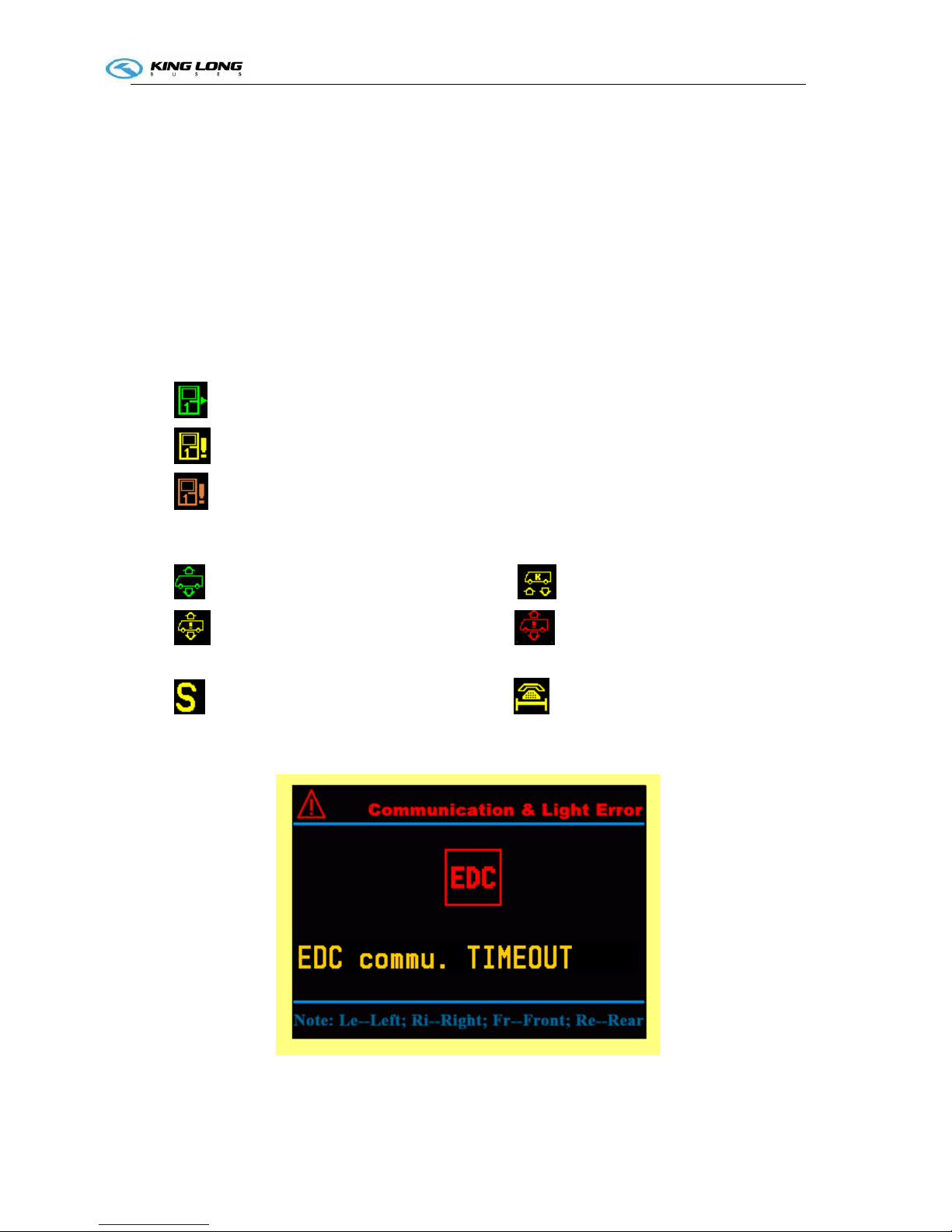
2.2 Error display Page:
Figure -2 text error information
Operation Instruction
I-5
If there is error exists, this page will show after driving information page when you press the page
change button.
Description:
Pictogram
:object name;
Text: detailed description of the error;
Errors can be displayed in this page:
Communication Error: EDC, EBS, TCO, AC, Front node, Top node, Cabin node, Rear node;
Light Error: high-beam, low-beam, reverse light, front fog light, rear fog light, brake light, turning
light
Other Error: brake circuit pressure open-load, fuel-sensor open-load, Engine cabin too hot, worn
brake shoes (1-6), fuel level low, water in toilet level low, air filter block,
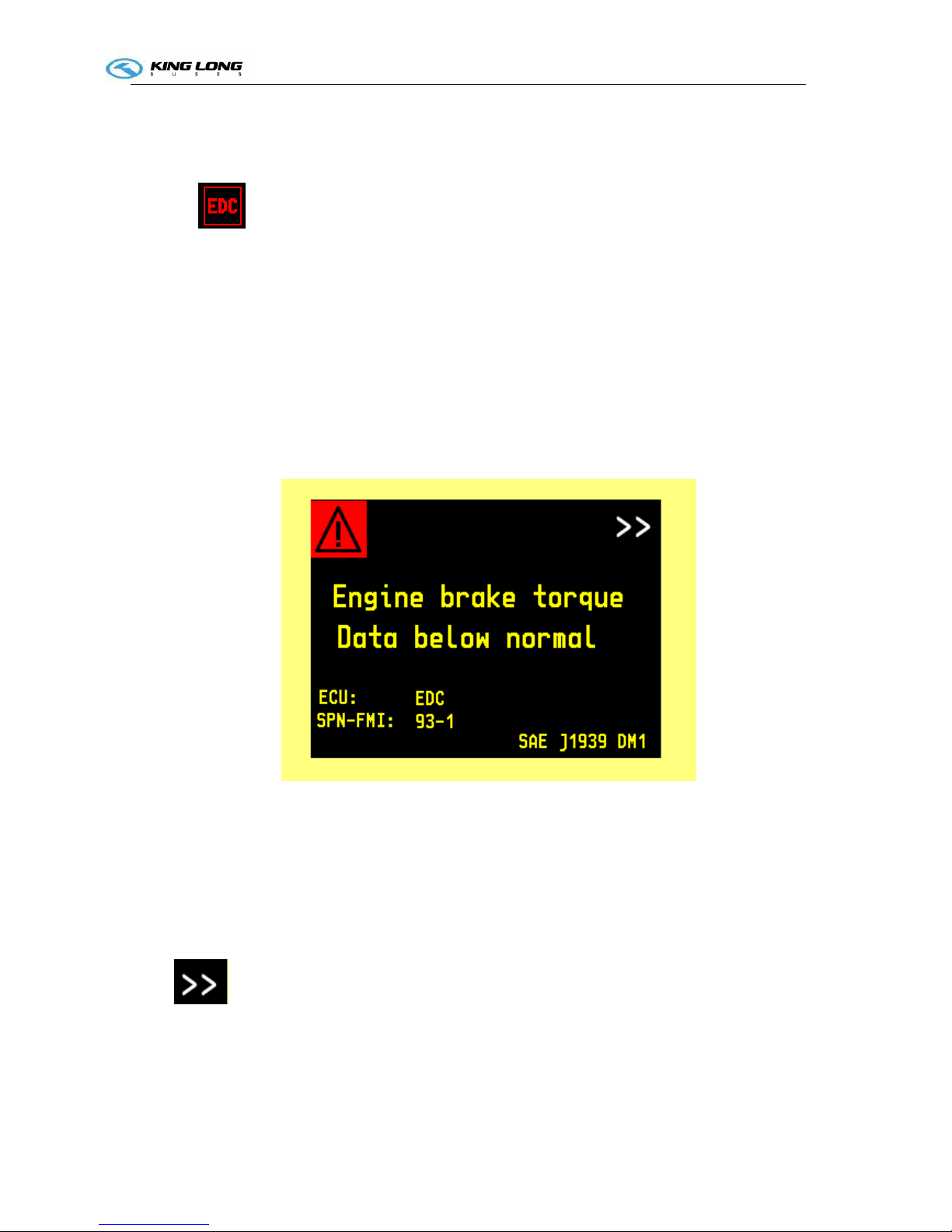
2.3 DM1 Diagnosis Information
Figure -3 DM1 display page
This page will show when some ECU sends out DM1 message. The diagnosed ECU must support
CAN diagnosis, and provides SPN-FMI code.
Line1: the object that has error (from SPN).
Line2: Error status (from FMI)
Line ECU: name of the ECU that sends the message (i.e. EDC, EBS, AC)
Line SPN-FMI: the SPN and FMI combination
: means this error is not the last one
Other contents are fixed
Operation Instruction
I-6
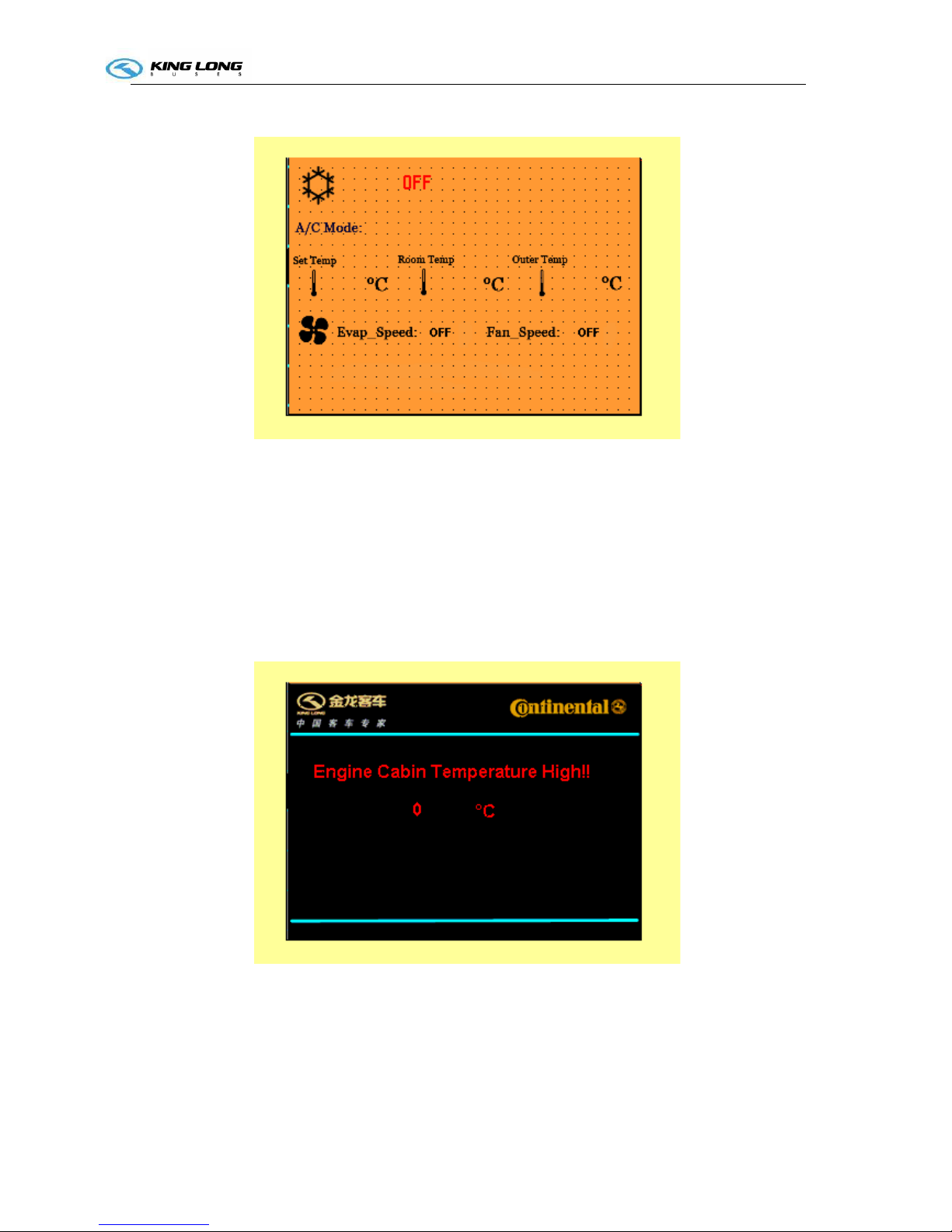
2.4 Air conditioner status
This page will appear is air conditioner is working and the communication is right.
A/C mode include: ventilation; heating; cooling; demist/defrost; auto mode; off
Set temp: the temperature currently set to be;
Room temp: the real ambient temperature in the bus;
Outer temp: outside temperature;
Evap_speed: OFF; High; Mid; Low
Fan_speed: OFF; High; Low
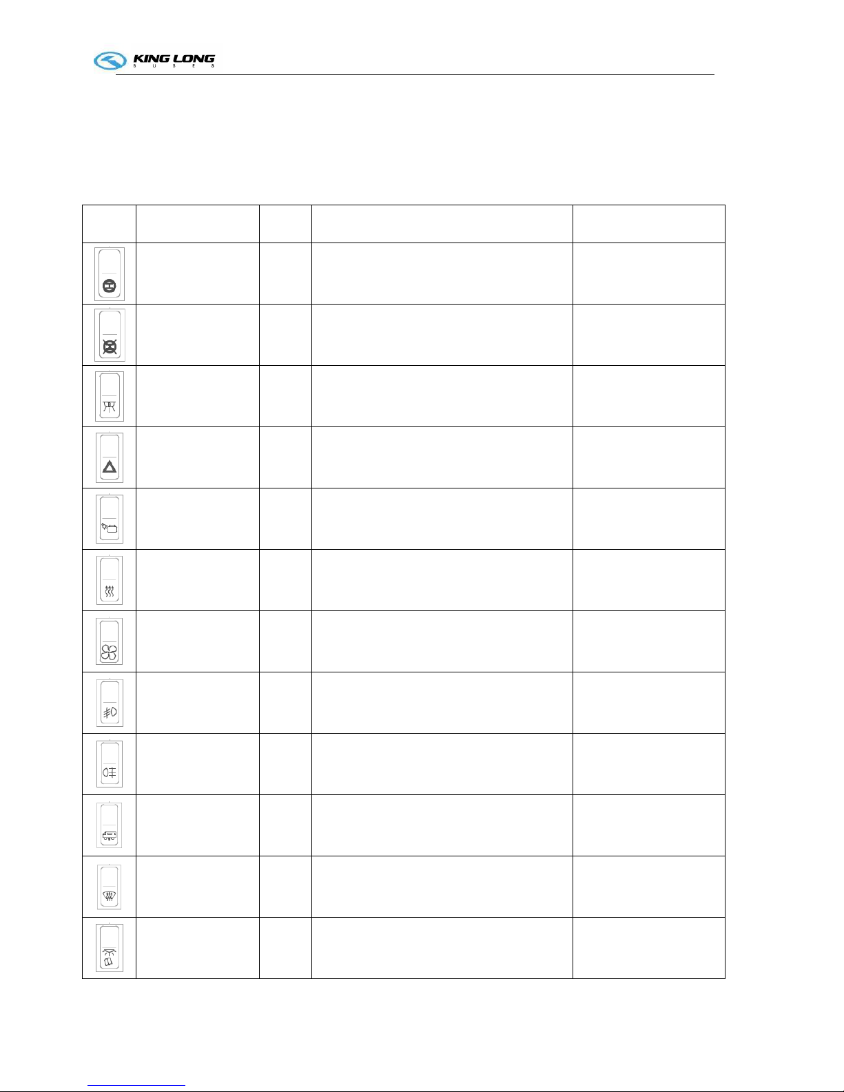
2.5 Engine Cabin Temperature high warning page
If engine cabin temperature is higher than 85°C, this page will appear automatically. The temperature
will show on the page. The driver need to press the page change button to switch to the driving page

Operation Instruction
I-7
2.6 Beeper warning conditions
Brake circuit 1 pressure low
Brake circuit 2 pressure low
Coolant level low
Hammer not at right position
Engine cabin temperature high
Oil pressure low (after engine running)
Service request
Left turning
Right turning.
Operation Instruction
SI-1
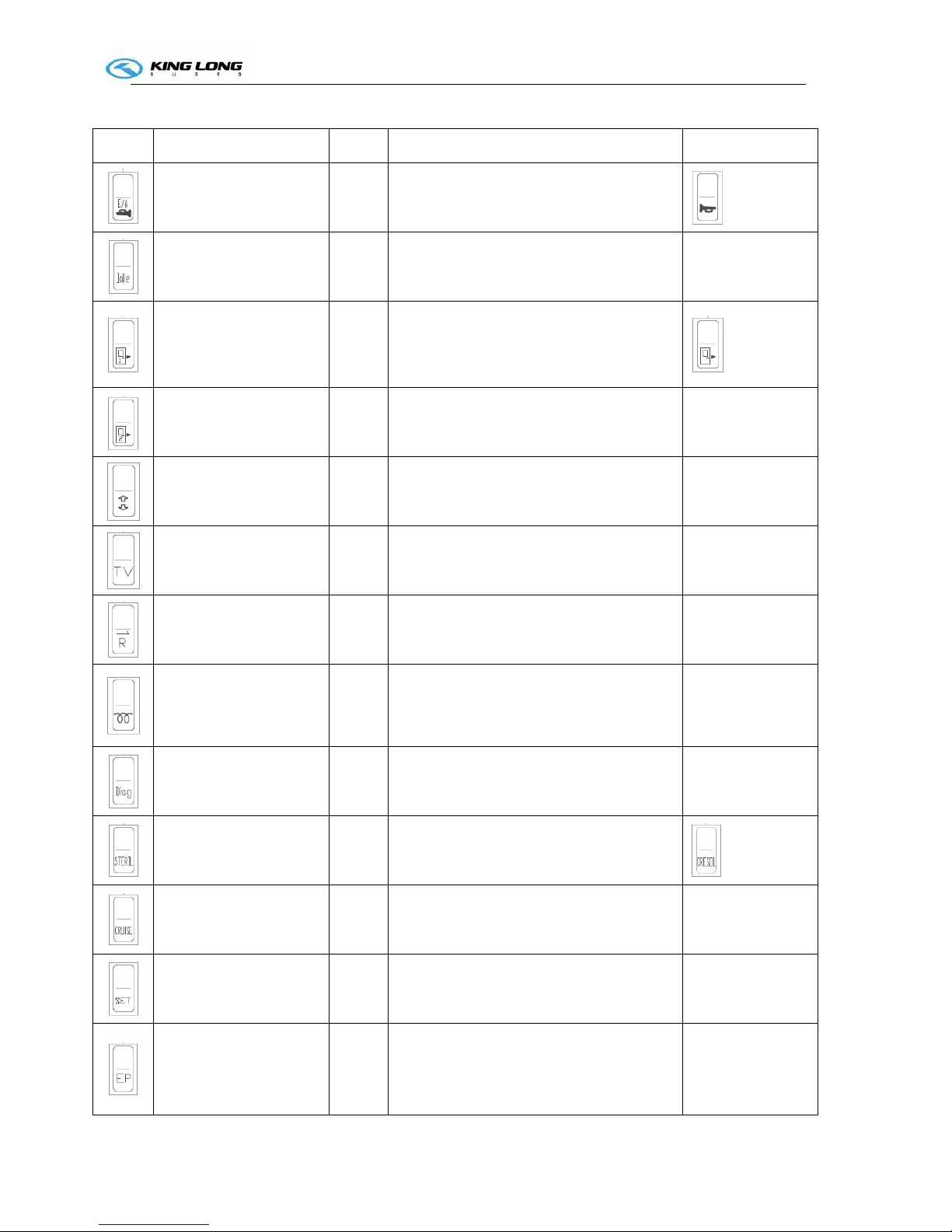
Illustration of switch and indicator
Number of switches and indicators and position may vary with vehicle model, please consult the flowing
sheet and use correctly according to actual condition of vehicle.
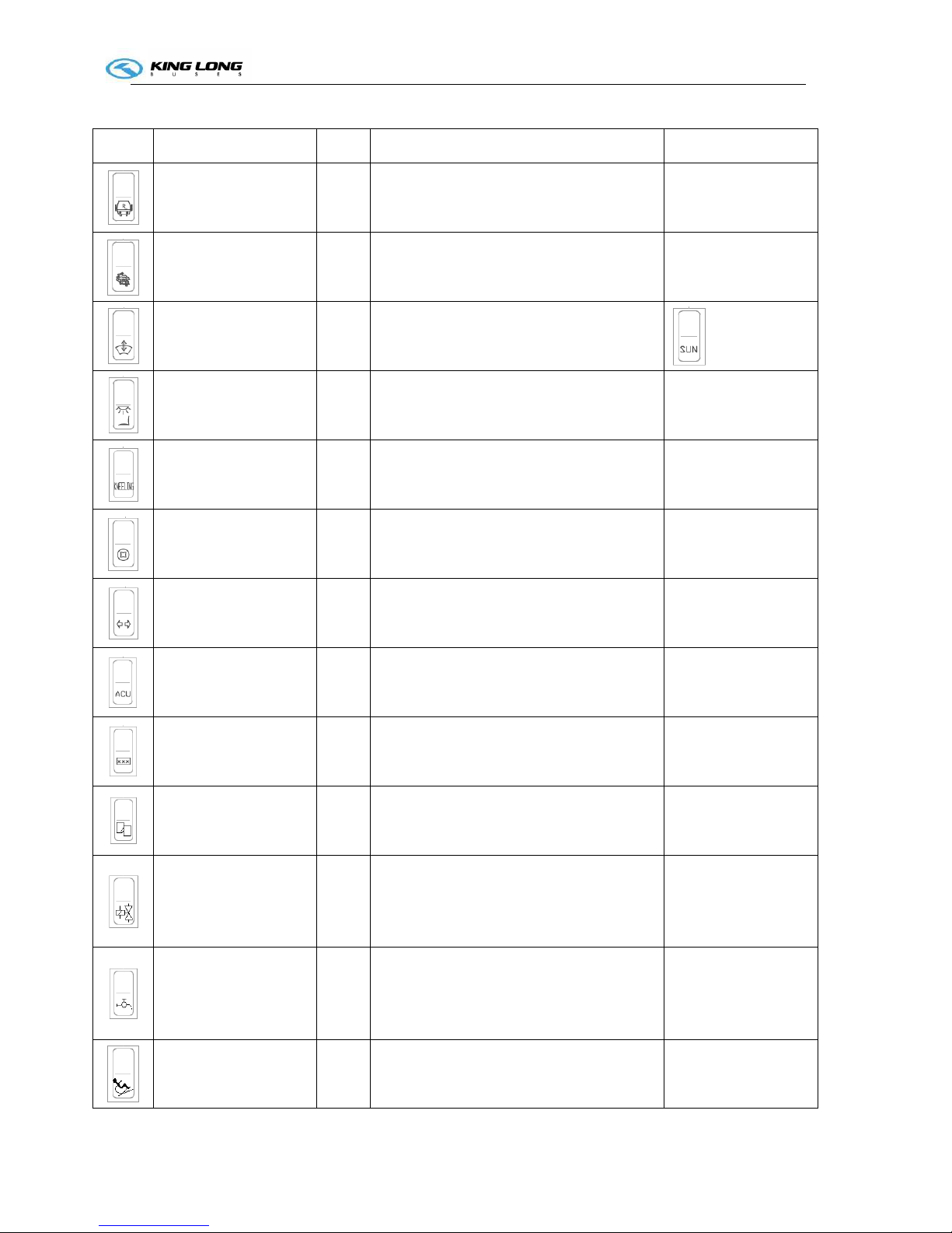
Switch
Name Color Function Notes
Retarder Green
Pressed on top: retarder is turned ON
Pressed on bottom: retarder is turned OFF
Retarder turn off
switch
Pressed on top: retarder is turned OFF
Pressed on bottom: retarder is turned ON
Daylight lamp
Green
Pressed on top: interior lighting ON,
Pressed on bottom: interior lighting OFF
Hazard lamp Red
when the vehicle have a screw loose, switch
it on, the whole vehicle lamps light
Luggage
compartment lamp
Green
Pressed on top: lamp lights ,
Pressed on bottom: lamp goes out
Compulsory
radiator
Green
Pressed on top: radiator working ;
Pressed on bottom: to turn it off
only use this button
when vehicle is stopping
Ventilator
Green
Pressed on top: ventilator is active,
Pressed on bottom: ventilator is turned off
Front fog lamp
Green
Pressed on top: front fog lamps ON,
Pressed on bottom: front fog lamps OFF
Rear fog lamp
Yellow
Pressed on top: rear fog lamps ON,
Pressed on bottom: rear fog lamps OFF
Vehicle raise/lower
Green
Pressed on top: vehicle raise,
Pressed on bottom: vehicle lower
only use this button
when vehicle is stopping
Defroster
Yellow
Pressed on top: windscreen heater ON,
windscreen heater OFF
Reading lamp
Green
Pressed on top: reading lamp ON, Pressed on
bottom: reading lamp OFF
Operation Instruction
SI-2
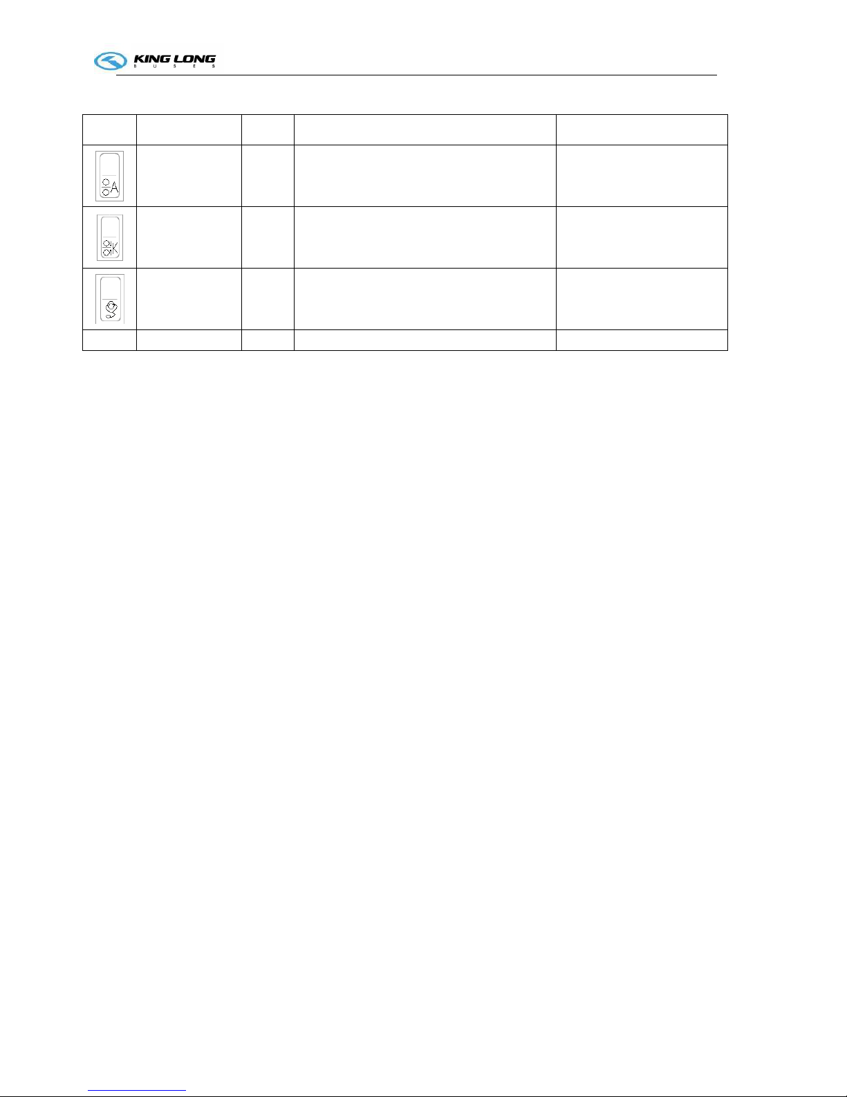
Switch Name Color Function Notes
horn Green
Pressed on top: air horn is active, Pressed on
bottom: electric horn is active
Engine idle Green
Pressed on top: engine idle speed raise,
Pressed on bottom: engine idle speed lower
adjust engine
speed
Front passenger door Green
press button once to open front passenger
door;
press button again to close
Rear passenger door
Green
press button once to open passenger door;
press button again to close
Electric curtain Green
Pressed on top: to raise curtain;
Pressed on bottom: to lower curtain
TV
green
Pressed on top: TV is turned ON,
Pressed on bottom: TV is turned OFF
Reversal monitor
Green
Pressed on top: reversal monitor turned ON,
Pressed on bottom: reversal monitories
turned OFF
Rearview mirror
defrost(preheating)
Yellow
Pressed on top: preheating ON,
Pressed on bottom: preheating OFF
Diagnose
Green
press this button to make a diagnosis of
engine, when engine indicate trouble
Disinfect Green
Pressed on top: disinfection turned ON,
Pressed on bottom: disinfection
turned OFF
Cruise
Green
Pressed on top: cruise function is active,
Pressed on bottom: cruise function isn't
active
we advise clients
not to use this
switch
Cruise setting
Green cruise setting
we advise clients
not to use this
switch
Emergency time-delay
parking
Red
Pressed on top: Emergency time-delay
parking function is active,
Pressed on bottom: Emergency time-delay
parking function isn't active
only used when
engine failure
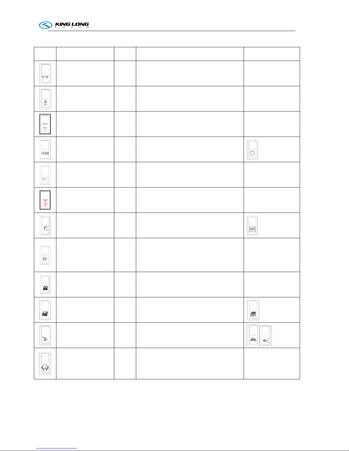
Operation Instruction
SI-3
Switch Name Color Function Notes
Exterior guidepost
Red
Pressed on top: turn on guidepost lamp;
Pressed on bottom: turn off guidepost lamp
Assistant brake
Yellow
Pressed on top: turn on assistant brake;
Pressed on bottom: to turn it off
only switch on when
vehicle need park
Vehicle level reset Green Pressed on top: vehicle level reset
Emergency power
Red
Pressed on top: emergency power turned ON
Pressed on bottom: emergency power is
turned OFF
Toilet power switch
Green
Pressed on top: Toilet power is turned ON,
Pressed on bottom: Toilet power is turned
OFF
Heater switch
Red
Pressed on top: to turn on heater ;
Pressed on bottom: to turn it off
TV overturn switch Green
Pressed on top: expand the TV,
Pressed on bottom: collapse the TV
Fresh air switch Green
Pressed on top: turn on the changing fresh
air function;
Pressed on bottom: turn off the changing
fresh air function.
Electric driver window
switch
Green
Pressed on top: the glass getting up;
Pressed on bottom: the glass getting down.
Electric driver window
defrosting switch
Yellow
Pressed on top: turn on defrosting function;
Pressed on bottom: turn off defrosting
function.
Rearview mirror
defrosting switch
Pressed on top: turn on defrosting function;
Pressed on bottom: turn off the defrosting
function.
Left side bin gate Green
Pressed on top: open the left side bin gate;
Pressed on bottom: close the left side bin
gate.
Operation Instruction
SI-4
Switch Name Color Function Notes
Right side bin gate Green
Pressed on top: open the right side bin gate;
Pressed on bottom: close the right side bin
gate.
Powerful/abstemious
transfer switch
Pressed on top: turn on powerful function;
Pressed on bottom: turn off abstemious
function.
Electric sun blind Green
Pressed on top: the sun blind getting down;
Pressed on bottom: the sun blind getting up.
Driver seat lamp switch Green
Pressed on top: turn on the driver seat lamp;
Pressed on bottom: turn off the driver seat
lamp.
Kneeling switch Green
Pressed on top: turn on kneeling function;
Pressed on bottom: turn off kneeling
function.
Coin box switch Green
Pressed on top: open the coin box;
Pressed on bottom: turn off the coin box.
Turning lamp switch Green
Pressed on top: turn on the turning lamps;
Pressed on bottom: turn off the turning
lamps.
ACU unlock switch Green
Pressed on top: ACU unlock;
Pressed on bottom: ACU lock.
For articulate plate
only
Inner guidepost switch Green
Pressed on top: turn on the inner guidepost;
Pressed on bottom: turn off the inner
guidepost.
Changing monitor
video switch
Green
Pressed on bottom: changing the monitor
video from cameras
Spare switch
Pre-heater solenoid
valve switch
Green
Pressed on top: turning on the pre-heater
solenoid valve for water way
Pressed on bottom: turning off
Press the switch while
turning on the
pre-heater ignition
switch
Pre-heater water pump
switch
Green
Pressed on top: turning on the pre-heater
water pump
Pressed on bottom: turning off
Press the switch while
turning on the
pre-heater ignition
switch
Handicapped footplate
switch
Red
Pressed on top: switching on the
handicapped footplate
Pressed on bottom: turning off
Power switch on
dashboard , control
switch in disable area
Operation Instruction
SI-5
Switch Name Color Function Notes
Height adjusting
switch
Green
Pressed on top: switching on the height
adjusting function;
Pressed on bottom: turning off
Side kneeling
setting switch
Green
Pressed on top: switching on the side
kneeling function;
Pressed on bottom: turning off
Engine
diagnostic
switch
Yellow
Pressed on top: switching on the engine
self-diagnostic;
Pressed on bottom: turning off
The engine diagnostic
indicator flashing 3 times
for each code
Operation Instruction
SI-6
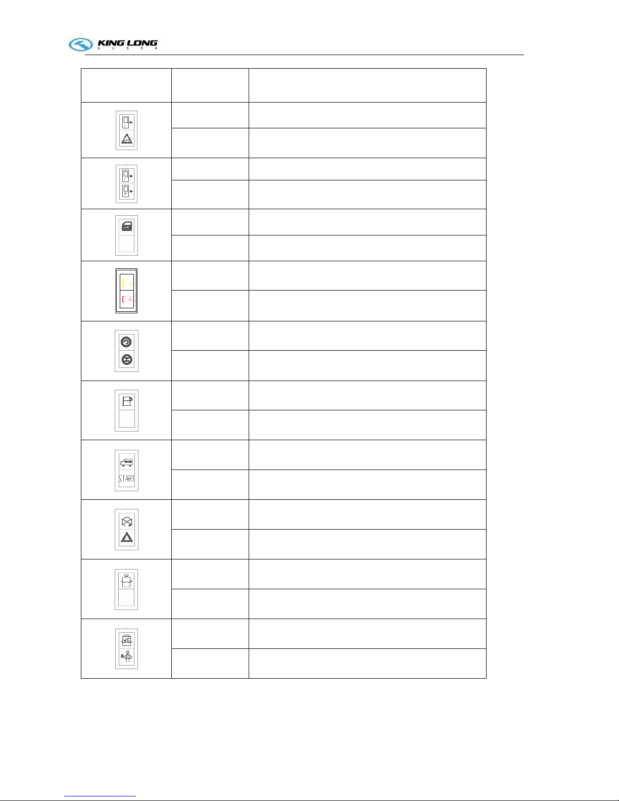
Indicator lamp
Color
Function
Red passenger door open indicating
Red natural gas leakage indicating
Red front passenger door open indicate
Red rear passenger door open indicating
Red exit has been open indicating
hollow plate
Yellow ECAS alarm indicating
Red ECAS fault indicating
Red gearbox fault warning indicating
Green retarder indicating
yellow Fuel filter seeper
Hollow plate
Yellow Maintain waiting
yellow Start
Red Stop
Yellow Alarm
Red Water level
hollow plate
Green WC
Red Service
Operation Instruction
SI-7
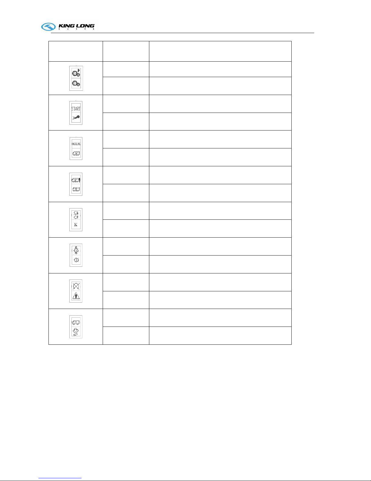
Indicator lamp
Color
Function
Red Transmission oil temperature too high
Red Transmission fault
White Start-up waiting
Yellow Over emission
Yellow Kneeling lamp
Green Normal height
Red Vehicle in abnormality height
Red Air chamber trouble warning indicator
Red 2
nd
height indicator
Yellow Side kneeling indicator
Red Transmission oil temperature warning indicator
Red Transmission trouble warning indicator
Red Engine major trouble
Red Engine small trouble
Yellow Engine maintenance indicator
Yellow Engine diagnostic indicator
Operation Instruction
P-H-1
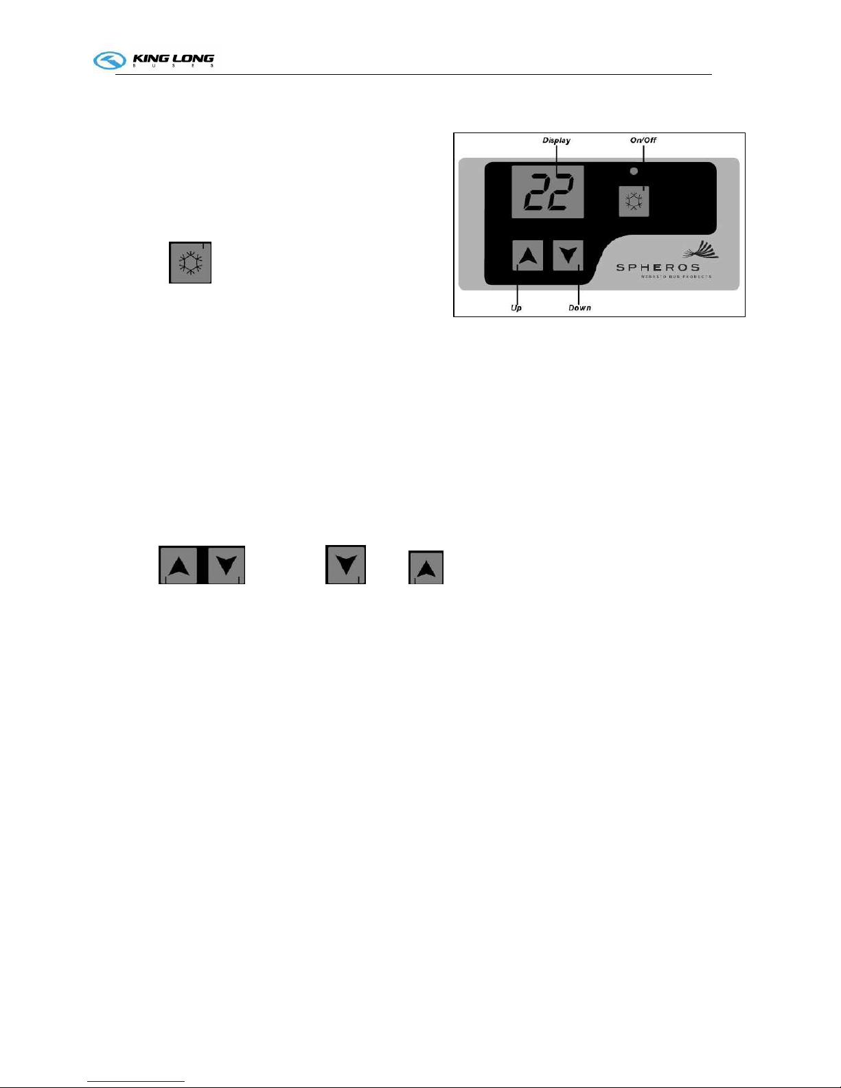
Spheros A/C Controller Instruction
1. Display
It indicates the internal temperature and the regulated
temperature.
PS: the display will always show the vehicle internal
temperature even when the motor is off.
2. Key
- On/Off
1st touch – turns on the equipment
- the equipment operates in refrigeration at high velocity
PS: If the led light is blinking, it indicates the compressor still has not started operating. If the light is on,
it indicates the compressor has started operating.
2
nd
touch – the equipment starts operating in refrigeration at low velocity.
3
rd
touch – turns off the equipment.
PS: It is always recommended to turn off the equipment before turning off the vehicle motor.
PS: When the air conditioner is activated for the first time, the compressor will be activated at
approximately 10 seconds. After the air conditioner turning off and its subsequent turning on (without
turning off the vehicle motor) the compressor will be activated at about 30 seconds.
HA – When the command panel shows HA, the compressor and the ventilators of the condenser will be
off for 3 minutes, after that, they will restart working again.
3. Key:
- turn down or up the desired temperature.
When you press any of these keys, the (blinking) display will show the selected temperature. For
turning it down or turning it up, keep pressing one of the keys until you get the desired temperature
value (minimum 16 e maximum 32 ). After 5 seconds without pressing one of the keys, the℃℃
temperature will be recorded and the display will once again show the temperature inside the vehicle.
4. Failure code
When the display shows one of the indications related below, it is an indicator of failures in the system.
HA – Indicates low or high pressure in the system. It may be a condenser obstruction or lack of gas.
OP – Sensor of temperature is open. Select one temperature below 24 so that the equipment may ℃
operate in refrigeration and above 24 so that the equipment may operate in ventilation.℃
SC – Sensor of temperature in short circuit. On such a case, the equipment will operate at an internal
refrigeration temperature of 24 .℃
AL – Indicates the alternator is not charging current.
Operation Instruction
P-H-1
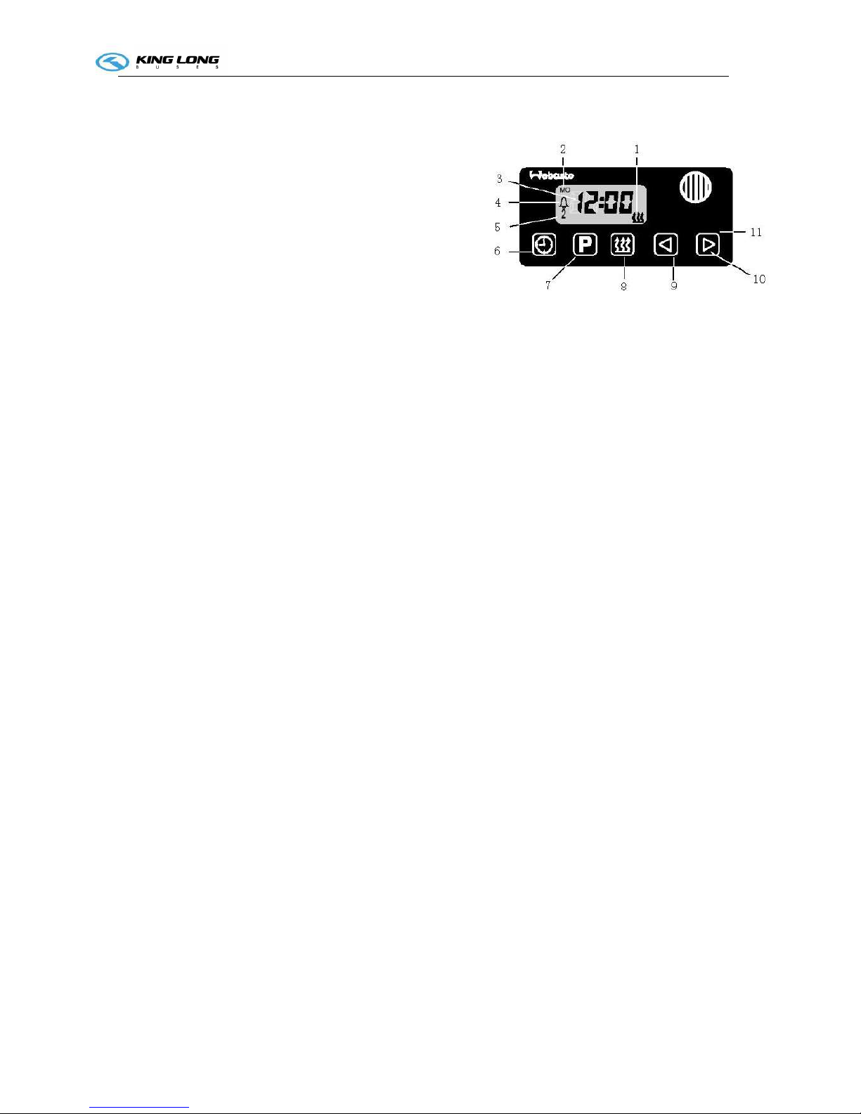
Pre-heater Operation (Webasto)
1. General
The standard digital timer enables you to preset the
start of the heater operation up to 7 days in advance.
It is possible to program 3 different starting times,
only one of which can be activated.
The standard digital timer features a wakeup alarm
function.
When the ignition switched on, the timer displays
the current time and the day of the week.
When the heater is switched on, the display and
the buttons are illuminated.
After the power supply has been connected,
all symbols on the display will flash.
The current time and weekday must be set.
2. Operation
The timer can be operated in that all flashing symbols
can be adjusted by means of the 10 and 9 buttons.
If the buttons are not pressed within 5 seconds,
the time displayed will be stored.
If the 10 and 9 buttons are pressed for more than
2 seconds, the fast time-setting mode is activated.
If the ignition is switched off while the heater is operating in the continuous mode, the
remaining operating time of 15 minutes is displayed and the heater continues to operate for this
period of time.
3. Switch the heater on
Manually: by pressing the button 8 (continuous heating mode)
Automatically: by programming the heater starting time
4. Switch the heater off
Manually: by pressing the button 8
Automatically: after the programmed operating time has elapsed.
With the heater running: by programming the remaining operating time
5. Setting time/day of the week
Press the 6 button for more than 2 seconds-time of the day if flashing-and set the clock using
the 9 and 10 buttons. Day of the week is flashing – adjust the day of the week.
6. Viewing the time
With the ignition switched off: press the 6 button.
7. Programming heater starting time:
1. heater “on” indicator
2. day of the week
3.
time display
4.
memory location
5.
alarm indicator
6.
time
7.
program selection
8.
instant heating
9.
reverse
10.
forward
11. panel

Operation Instruction
P-A-5
Press the 7 button – the memory location is flashing – using the 9 and 10 buttons set start of the
heater operating time. Day of the week is flashing- set the day of the week. By repeatedly
pressing the 6 button, memory locations 2 and 3 can be programmed or the time display mode
can be reached.
8. Recalling/erasing preset times
Repeatedly press the 6 button until the desired memory location is displayed. To erase the
preset time, press the 7 button several times until the time of the day is displayed instead of the
memory.
9. Programming duration of operating time The heater must be switched off. Press the 9
button for 3 seconds – operating time is flashing – and set the desired operating time (10 to 120
minutes) using the 9 and 10 buttons.
10. Setting the remaining operating time
Set the desired remaining operating time (1 to 120 minutes) using the 9 and 10 buttons. The
remaining operating time refers to the time the heater still continues to remain in operation and
the ignition switched off.
11. Setting the wakeup time
A wakeup time can only be programmed on the standard digital timer. The wakeup time is not
bound to a specific day of the week.
Repeatedly press the 7 button until the bell symbol appears on the display. Set the
desired wakeup time using the 9 and 10 buttons. The alarm clock turns off after 5 minutes or
when one of the buttons is pressed.
12. Recalling/erasing the wakeup time
Repeatedly press the 7 button until the bell symbol appears on the display – read off
wakeup time. To erase the wakeup time: press the 7 button until the bell symbol is no
longer visible on the display.
13. remote control
Possible by means of an optional external “instant heating” button
14. Vehicles with ADR equipment
On ADR vehicles it is not possible to program a preset starting time. The remaining time is
shown on the display while the heater is in operation. The clock can be set. The alarm clock
function can be programmed on the standard digital timer.
Operation Instruction
P-A-5
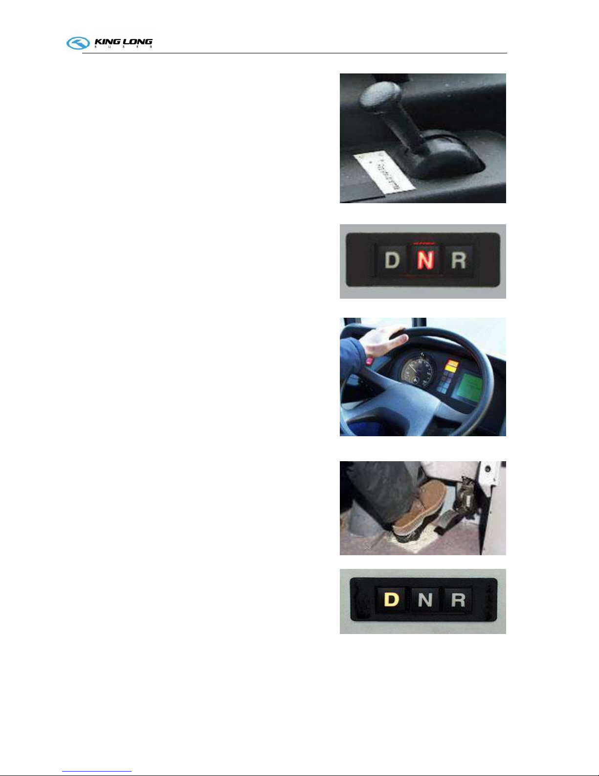
Transmission application (Voith)
Starting the engine
First apply the parking brake.
No button of the push-button switch may be depressed
during starting. Bring all buttons into neutral position by
depressing the button marked ’N’: all but-tons are released,
the ’N’-button
is illuminated.
Under certain conditions it may be possible to start the
engine after pressing any button other than the ’N’-button. In
that case, however, no gear will be engaged even if the
push-button switch indicates this. Make sure you only start
the engine after having pressed the ’N’-button.
Driving forward
If your vehicle is equipped with a safeguard against
inadvertent gear engagement this facility must be operated
first. For that purpose step onto the brake pedal.
Press button ’D’ while the vehicle is at standstill and the
engine idling.
When the brake is released now, the bus will start moving.
Note: If the vehicle fails to move off possible reasons may
be:
– the accelerator was actuated while selecting a gear,
– the safeguard against inadvertent gear engagement was not
released.
Please also consult the operating instructions of the vehicle.
When moving off on a gradient, step on the accelerator
before releasing the brake in order to prevent the vehicle
rolling back.
Note: Driving in the partial load range rather than at ful
throttle or kickdown mode will have a positive
effect on fuel consumption.

Operation Instruction
0-G-2
Driving in kickdown mode
For higher acceleration, depress the accelerator beyond the
full-throttle pressure point. This causes the transmission to
change gears at a higher speed.
Note: Driving in kickdown mode will increase fuel
consumption.
Driving with buttons
1 , 2 or 3 (if available) pressed:
When the transmission hunts between two gears when
driving uphill, press the button for the lower of the two
gears. This will prevent engagement of the higher gear.
Note: Driving with buttons 1, 2 or 3 pressed will increase fuel consumption.
Breaking
With the DIWA transmission breaking is free of wear.
Actuating the brake pedal or the manual switch for converter
brake will apply the converter brake.
Depressing the brake pedal further will apply the service
brake.
Please note when braking on a slippery road: the converter
brake only acts on the driven wheels.
On vehicles without ABS the converter brake should therefore
be disabled when road conditions are poor (e. g. in ice or snow)
in order to avoid rear wheel lock-up and a possible loss of
control over the vehicle.
Switch off the converter brake via the converter brake switch,
if available
Hunting between gears Pressing the button
4 - 3 3
3 - 2 2
2 - 1 1

Operation Instruction
0-G-3
In vehicles equipped with ABS the converter brake switch is
mostly not availably. The location of switch and its handling
are described in the operating instructions of the vehicle.
Stopping
During short stops (e.g. traffic lights, bus stops) the selected
button remains depressed and the vehicle is held by the vehicle
wheel brake or the parking brake.
ANS-activation
Automatic Neutral at Standstill:
Conditions for activation of ANS :
– accelerator in idling position,
– brake signal,
– driving speed below 1 km/h,
– forward gear selected.
The power flow between engine and transmission is interrupted.
This results in fuel savings.
Reversing
Press button ’R’ while the vehicle is at standstill and the
engine idling and - if available – the reverse gear inhibiter
button. A change from ’Forward’ to ’Reverse’ or viceversa is
only possible after operation of the ’N’ button.
Never engage reverse gear when moving forward – danger of
accident!
Parking
For longer stops or when switching off the engine, switch the
transmission to neutral (button ’N’) and apply the parking
brake.

Operation Instruction
0-K-1
Open/close the passage door.
For the king-long city bus, the method of open and
close the passage door is different to above. Details
please see the right drawing. The red button is close
button; the green button is open button. This device
usually located on the bin under the driver seat
compartment. If need open or close the front
passage door without remote controller, directly
press the green button or red button. The middle
passage door and the rear passage door of city bus
controlled by the knob switch on driver zone.
Appendix:
The following is door remote controller of King-Long.

Operation Instruction
0-K-2
Door emergency switch
The door emergency switch is located on right upside of the
door.
Please rotate the switch and throw open the door in
emergency.
Special attention: The door emergency switch is only used in
the emergency mode. Please don't rotate the door emergency
switch in driving for fear of danger.

Operation Instruction
0I-1
Adjustment of the driver's seat
The driver's seat may be made proper
adjustment for the back and forth as well as
the backrest angle according to requirement
of the driver.
Handle 1:seat angle adjustment
Handle 2: back and forth adjustment
Note: Number of handles varies with vehicle
model
Attention!
The seat should not be adjusted during
driving
to ensure driving safety.
1
2

Operation Instruction
0I-2
Horn button
It is on the steering wheel. The horn is hooting when
pressing the button 1.
The type of steering wheel may vary with vehicle model.
Please use the horn only when strictly necessary to warn
other drivers and pedestrians.
Model 1
1

Operation Instruction
0I-3
Adjustment of the steering wheel
Rotate the loosening button 1. Adjust the height and the inclination of the steering wheel to the desired
position. After adjusting, press the regulating handle or button down to lock the steering column.
Note: Number of handles varies with vehicle model
Attention!
Adjust the steering wheel only when the vehicle is
stopped and the parking brake is on.
After adjusting, press the regulating handle or button
down in order to lock the steering column.
1

Operation Instruction
OI-4
Ignition switch
Position of the ignition key is shown in fig.1.
"K" KEY: for inserting and drawing out position of the
startup key
1."L" LOCK: Insert or remove the key in this position.
2."A" ACC: Power supply of the instrument is switched on
3."O" ON: Normal driving position
4."S" START: Initiating position of the engine, and the key
may rebound to the "ON" position automatically after the
startup
.
Before starting the engine, turn the key to the “ACC”
position and then to the “ON” position. At this point, three
lights (red, yellow and green) on the dashboard will come on.
Wait for the lights to go out completely before you start the
engine. However, make sure that all of the self-check lights
have gone out completely before starting the engine. Allow
the engine to run at idle speed for three to five minutes after
it has been started; but never let it run for more than 10
minutes at idle speed. If the vehicle does not move, increase
the fuel to the throttle modestly to increase the rotational
speed of the engine a little; this will also prevent the early
wear and tear of the engine. Allow the engine to run at idle
speed for three to five minutes before turning it off.
Note:
1. Turn the ignition key to the OFF position after the engine
has been turned off and has stopped running.
2. If the first attempt to start the engine is not successful, please wait two minutes before trying again.
3. If the engine fails to start after three attempts, check the fuel supply system. If the vehicle runs on
natural gas, check the gas supply system.
Attention!
1. Do not remove the ignition key while the vehicle is in movement. And the ignition key should be
turned to the LOCK position only after the engine shut down.
2. If engine can not start successfully for the first time, try again after 2 minutes. Please check the fuel
supply system if the engine can not start for the third time.
3. When leaving the vehicle, even for a short period, take the key out to avoid operation of the vehicle
by children or unauthorized persons.
1

Operation Instruction
OI-5
Lamplight operating handles
The lamplight operating handle is
located on right underside of the
steering wheel, which control the front
small light, headlamp, headlamp
dimming, left and right steering by two
different motion modes
OFF Indicating that the headlamp
and the small lamp are all off.
Is the small lamp indication.
The small lamp, the instrument light
and the side indicator lamp will all be
turned on when clock wisely rotating
the handle to position of this
identification.
Is the Is the headlamp indication. The headlamp, small lamp, meter lamp and width lamp will all be
turned on when continuously clockwisely rotating the handle to position of this identification.
Is the turning indication. By back and forth motions of the operating handle may control the
left and right turning lamp and that on the dashboard.
Is dimming indication. Uplifting the operating handle gently may actuate the headlamp
dimming.
Note:
It’s important to dip the lights promptly when approaching an upcoming vehicle in order to avoid
dazzling its driver with the high beam of the headlight.

Operation Instruction
OI-6
Wiper operating handle
The wiper operating handle is located on right underside
of the steering wheel. (model 1~3)
OFF Out of work
INT interval wiper operation step
LO Slow wiping
HI Quick wiping
The wiper operating handle is located on left underside of
the steering wheel. (model 4)
Rotary handle
0 Out of work
J interval wiper operation step
1 low speed wiper operation step
2 HI high speed wiper operation step
The wiper may spray water by pressing the end of the handle.
The wiper may spray water by pressing the end of the
handle. The shifts of the retarder may be converted by back and forth motion of the handle.
Note: do not actuate the wiper without water; press the washer button as needed, then actuate the wiper.

Operation Instruction
OI-7
Retarder operation (for retarder)
The hand lever can be mounted under the steering wheel
or built into the dashboard. This hand-operated control
generally has 5 control positions:
Position 0: off
Position 1: 25%
Position 2: 50%
Position 3:75%
Position 4: maximum braking effect
An indicator light is lit when the retarder is in use.
Notice:
If you vehicle is fitted with a retarder but without a
dashboard indicator light, it is essential to have one
fitted.
Should the indicating light be on without actuation of
the retarder, this would mean a unfit in the retarder
function.
If the light does not come on when the retarder is
operated, check the bulb.
Don’t forget to return the lever to position 0 once the
vehicle has stopped to prevent unnecessary consumption
of electric current. This can be done in a single
movement, without pausing in the intermediate positions.
Terca & Telma handle

Operation Instruction
OI-8
Safety hatch
The safety hatch is located on scaffold of
the vehicle. Please open the safety hatch
according to the above diagrammatic
representation and illustration for
escaping in case of danger.
Model 1

Operation Instruction
OI-9
Safety hammer
The safety hammer is located on the side window.
Please take down the safety hammer and break open
the safety window for escaping in case of danger.

Operation Instruction
0I-10
Prompt stop switch for get off
The stop switch is located at the grab rail
(see the right picture).when the vehicle is
going to arrive at bus stop, the passenger
who need get off press the switch to remind
the driver for stopping.

Operation Instruction
O-E-1
Switch control box (Model: CQ2025)
CQ2025 A wiring diagram (Printed on opposite cover of the switch control box)

Vehicle Starting and Driving
S-1
Preparatives for vehicle operation start up:
Check daily, before turning engine on:
1. Check oil level of the engine
The warning “Engine oil pressure” is displayed as a signal
item on the combination instrument when the oil pressure
is too low, the alarm buzzer sounds, the warning light
STOP comes on, stop the engine and check engine oil level
at the dipstick. Provide immediately for the oil
replenishment to its correct level.
The oil level should always be checked with the vehicle
parked on level ground, before starting the engine up, or at
least 5 minutes after having shut it down.
Open the engine compartment hood.
Take out the oil dipstick, and clean it with a clean cloth
without loose threads, and put it back into its place fitting it
in completely.
Once again pull out the dipstick and check the oil level.
a. The oil should not exceed the maximum level.. drain
the excess.
b. If the oil is at operational level, do not add more oil to
the crankcase.
c. If the oil is at or below the minimum level, add the
same type and brand of oil to the crankcase as that
already there, until reaching the maximum level..
After the checking, replace and fit the dipstick completely
back into its place.
If the oil level is checked after the engine has been run for
a period of time, then it should take at least five minutes
before the measure to ensure the oil back flow to the oil
sump in full.
Oil level dipstick
Oil inlet

Vehicle Starting and Driving
S-2
2 Check level of the coolant
The coolant level is automatically
monitored.
If coolant level gets too low,the digital
indicator displays a driver information
on the combination instrument. In this
case, park vehicle in a safe place as
traffic conditions permit, stop engine
and visually check the coolant level.
Check the coolant level only when the
engine doesn’t work and its temperature
is below 50℃.
The anti-freezing rust-inhibiting engine
coolant level can be observed from the
observe pipe.
The coolant level should be between the maximum level (MAX.) and minimum (MIN.) level indicators in
the compensation tank.
If it is necessary to add coolant to the system:
a. Place the heating system command in the position of maximum heating potency.
b. Add the coolant to the system up until the maximum level indication. Only use coolant which is
recommended.
c. The compensation tank cover should not be opened when temperature of the coolant is still high to
avoid being scalded Place the lid on the system and turn it to the limit.
d. Pressure valve of the compensation tank should be opened when adding the coolant to eliminate air in
coolant pipeline of the diesel engine.
e. Run the engine for a short time at varied rotations.
f. Stop the engine and check the coolant level.
If necessary add more coolant to the system
Anti-freeze and antirust solution (mixture of glycol and water) should be added to cooling system from
time to time to avoid sediment, frost, oxidation and increase boiling point.
Note: When adding coolant, please choose the same model to avoid sediment. If coolant is degenerative,
replace it immediately.
Coolant specification as shown below: users should choose products produced by normal factories
according to requirement
Observe pipe

Vehicle Starting and Driving
S-3
3 Fuel pre-filter with water separator (drain accumulated water)
Draining accumulated water
On a daily basis, check the lower cup of the
water separator. If there is water in the cup,
unscrew the draining plug one or two turns, to
drain the accumulated water.
After draining the water, tighten the draining
plug correctly.
When the accumulation of impurities in the
lower cup is noticed, take the vehicle to a
workshop to carry out its cleaning.
Changing the fuel pre-filtering element
The fuel filtering element should be changed
periodically,
at the intervals recommended in the
maintenance manual.
If however, the filtering element is easily saturated needing substitution at very short intervals, this is an
indication of the accumulation of impurities in the interior of the fuel tank, and the cleaning of the latter
should be carried out.
In order to change the fuel filter element, take the vehicle to a Dealer or a King-Long Workshop.
Fuel system discharge
Activate the manual pump until feeling resistance on pumping.
Start up the engine without accelerating. If the engine
does not start running in 20 seconds, interrupt the startup
and wait at least one minute before trying again.
If the engine insists on not working, repeat the discharge
operation.
Leave the engine running for about a minute to completely eliminate the air from the system by way of
the auto-discharge system.
In order to reduce environment pollution problems, do
not drain the residues accumulated in the water separator directly into Nature (rivers, lakes or soil). The
drained residues should be collected in appropriate containers
and taken to receiving centers to have proper final destination (see local legislation).

Vehicle Starting and Driving
S-4
4. Fuel level
Turn the ignition key to drive position (on).
Check the fuel level on the indicator. If necessary, fill up the
fuel tank.
(but direct viewing by open the tank cover is preferred).
Eliminate deposite water in diesel filter in time and check fuel
pipe for no leakage. Ensure sealing performance of fuel tank and
before opening fuel tank, wipe up clay and dirt.
Before filling up, shut down engine.
Do not drive vehicle to empty tank. When the level indicator is
on the red bar, refuel the vehicle to avoid air from entering the
fuel system.
Fill the tank only with good quality fuel free of contaminants.
The fuel might as well be filled up when running in the humid
area to avoid inner rustiness.

Vehicle Starting and Driving
S-5
5. Vehicle lighting, intermittent lights and brake lights
Check all instruments and indicator lamps for normal, especially the head lamp, the turning lamp, the brake
lamp, the reversing lamp and the danger alarm lamp.
Check the bulb and the switch for their damage. To carry out the lamp substitution, hands should be very
clean. If possible handle new lamps with tissue paper.
Clean the external of all instruments and indicator lamps to ensure clear indication.
Attention!
The traffic laws regulate the location, lighting intensity, and color of the lenses and the quantity of
lanterns for each type of vehicle. The King-Long vehicles leave the factory in strict obeyance of these
specifications. Traffic safety depends on these factors; therefore do not change the place of the lanterns.
Substitute the damaged lanterns only for other original ones. Remember that a change of lantern colors
can confuse other motorists and result in serious accidents. Avoid unnecessary lantern adaptations.
When substituting lamps, use the same type and potency as the original lamps. Do not carry out any
lamp adaptation in the headlights, as this will affect their adjustment and performance, putting the
vehicle traffic safety at risk.
On a regular basis revise the illumination system, keeping it always in perfect working conditions.

Vehicle Starting and Driving
S-7
6. Check the level of AdBlue and the daily maintenance of SCR system
(1) Check the level of AdBlue.
When the vehicle key rotate the ON position, the LED
screen of combination instrument will display the
remain volume of the AdBlue, please see the right
diagram.
The AdBlue consumption is 5 percent of the fuel consumption. If the remain volume of AdBlue is less
than 12%, the alarming lamp will flash and you need add AdBlue. If the remain volume of AdBlue is less
than 6%, this lamp will light and the power of engine will be declined forcibly. This will cause the
emission substandard and it is not good to engine.
(2) The daily maintenance of SCR system
Please add the AdBlue when it is insufficiency. Ensure
the AdBlue meet the requirement. Check the SCR
system is well enough and has no leaking before driving.
There is obvious add mark in AdBlue tank. If add
substandard AdBlue, must stop the vehicle right now
and clean the AdBlue tank, re-filling the qualified
AdBlue. The air filter should be clean and replace
regularly.
Special attention:
If the AdBlue spill in skin, mild irritation may occur.
Wash off with soap and water. If the AdBlue spill in eye,
irrigate eyes with large amount of water. The AdBlue is
Non-combustible, if heated water evaporates and
ammonia will be released.
The volume of AdBlue

Vehicle Starting and Driving
S-8
7. Drain water in air tank
Open the water drain valve of air tank to drain oily water fully. If too much oily water is bled, check to
see if desiccant needs to be replaced in air drier. (This may be avoided when adopting the automatic drain
valve but it should be checked every two weeks)

Vehicle Starting and Driving
S-9
Check daily after turning engine on:
1. engine oil pressure
Run the engine.
The information on engine oil pressure can be requested through the driver information digital display.
If the oil pressure is too low, the oil pressure is automatically shown on the combination instrument.
Indication of the oil gauge will show a high value after the cold start of the engine and then it should be
kept within the range of 0.3-0.5Mpa (3- 5kg/cm
2
) along with the increment of the oil temperature as well
as the normal engine speed.

Vehicle Starting and Driving
S-10
2. Pneumatic pressure
The air pressure gauge indicates the reserve pressure individually for the front and rear service brake
circuits.
The reserve air pressure in each brake circuit must be sufficient for the correct operation of the brake
system.
The STOP warning light comes on in case of low brake pressure in the service brake or parking brake
circuits.
Attention!
If the driver information indicator displays the warning “brake pressure” and the STOP warning light
comes on with the engine running, it will be an indication that the air pressure is excessively low. Do not
drive the vehicle if the air pressure gauge displays low air pressure in one or both brake circuits, as the
service brake could fail resulting in serious accident.

Vehicle Starting and Driving
S-11
3. Tachograph working order
Indications on tachometer scale:
a. Green zone – operating range of maximum
performance
b. Yellow zone –
c. Red zone – engine overspeed range (risk of
immediate engine damage)
Always observe tachometer while driving the
vehicle.
Whenever possible keep engine running within
the economical range.
On downgrade, select an adequate gearbox
speed and monitor vehicle speed to avoid
engine operating in the danger range (red zone).
When the exhaust-brake is operating on down grades, select an adequate gearbox speed to keep engine
speed within efficient exhaust-brake operation (yellow).
Always avoid engine over revving (red zone), as engine operation in this speed range can end up in
immediate engine damage or seriously jeopardize its durability.
The yellow range with red reticle can be used occasionally when the exhaust-brake needs to be used at its
efficiency limit, however, at risk of engine durability. Therefore, do not operate in this range in a normal
or usual way.

Vehicle Starting and Driving
S-12
4. Steering play
Steering wheel play
Run the engine at idle gear and straighten the front
wheels forwards.
Turn the steering wheel alternatively to the right and
to the left.
The steering play (free movement of the steering
wheel) is measured on the perimeter of the steering
wheel and should be between 20 and 30 mm.
A

Vehicle Starting and Driving
S-13
Control periodically, at least once a week:
1. Check tire for abrasion and pressure and tire nut for fixture
The vehicle’s safety and performance depend considerably on the state of the tires, reason why they
should be checked daily.
Before driving a vehicle, check charging pressure of tire for normal, tire for damage, tire nut for fixture.
Note: At initial 50km, please tighten tire nuts of new vehicle to specified torque in appendix.
Tire pressure
Keep the tires always correctly calibrated. The inflation pressure should be checked with the tires cold at
least once a week.
After driving the vehicle for some time, the tires heat and in consequence of the heat, the inflation
pressure increases. Never, under any circumstance, empty heated tires to reestablish the recommended
inflation pressure.
The pressure difference between the assemble tires on the same axle should not be superior to 0.1 bar.
Wheel hubs
Keep them always clean, eliminating eventual mud or other dirt adherence. Substitute the damaged and/or
deformed hubs. The utilization of refurbished hubs is not recommended.
Wheel nut
Without fail re-tighten the wheel fastening nuts of new vehicles after running 50km.
The wheel fastening nuts should be retightened, crosswise, in turns, observing the recommended
tightening torque according to the type of fastening nut. If a torque meter is not available, tighten the nuts
strongly, using the vehicle tools without additional levers.

Vehicle Starting and Driving
S-14
2. Air cleaner (activate the dust discharge valve to loosen accumulated dust)
The maintenance of the air cleaner is made up of the
substitution of the filtering elements and should be
done only when the maintenance indicator indicates
the saturation of the element.
The cleaning of the main and safety filtering elements
is not recommended. The re-utilization of the filtering
elements can result in deficient filtering of the air and
cause serious damage to the engine.
When washing the engine, conveniently protect the air
inlet with a plastic or similar material to avoid the
infiltration of water to the air filtering element. After
washing the engine, remove the protection from the air
inlet.
Periodically press the dust discharge valve with your
hand, in order to incomplete the dust which possibly
be caught in the internal part maintaining them clear.
At the same time, check clip connecting rubber hose
of air intake system with steel tube in case of dust
entering air intake system due to looseness and
decrease in engine life.
The air cleaner restriction is electronically controlled.
If the indication of saturated air cleaner appears in the
display of digital indicator in combination instrument,
send the vehicle to a King-Long Dealer or authorized
workshop to inspect and clean the air intake system
and substitute the main filtering element.
Indication
The main filtering element of the air filter should be substitutes after maximum 2 years use.
The safety filtering element (optional) should be changed at every third main filtering element
substitution, or after maximum 2 years of use.
Model 1
Model II
1 automatic dust discharge valve

Vehicle Starting and Driving
S-15
3. General leakages (water, oil, fluids and fuel)
Check the engine, the transmission, the driving axle, the steering system, the cooling system and the oil
pipeline, the air pipeline of the complete vehicle for their leakage.

Vehicle Starting and Driving
S-16
4. Fastening and state of seat belts
Check buckle of the safety belt of the driver seat for normal and ensure for its lockup under the following
situations when fastening the safety belt.
● The body dashes forward all of a sudden;
● The vehicle makes an emergency braking or an abrupt acceleration;

Vehicle Starting and Driving
S-17
5. Check emergency devices and driver’s tools
Such as extinguisher, crosstie for blocking vehicle, emergency hammer, jack and etc..
Fire extinguisher:
The pulse super-micro powder fire extinguisher is fixed
in the engine compartment, when the compartment is on
fire, the fire extinguisher activate automatically or is
active by manual work to eradicate the fire
The fire button is usually located at auxiliary instrument
desk in the driver compartment where people could
operate it easily.
Operation:1. When the engine compartment caught fire,
the driver should stop vehicle and switch off engine
immediately, open the fire button cover, and press the
fire button, start-up fire extinguisher
2.Fire extinguisher may start-up automatically when
it catches fire or its temperature arrives at 170℃.
Important hint:
1. Fire extinguisher can be used for one time only,
DO NOT press the fire button except for
emergency condition.
2. The fire extinguisher can not start–up by press the
fire button manually if the vehicle battery is dead or
power turn off.
3. If the vehicle needs to be repaired, you could take
away the anode and the cathode. And put them back
after the reparation completed.
Inner fire extinguisher is fixed under the passenger’s chair, when
vehicle caught fire, stop vehicle and use the fire extinguisher.
Fire extinguisher
Fire button
Extinguisher

Vehicle Starting and Driving
S-18
6. Working order of windshield wipers and conditions of wiper blades and arms
Regularly check the windshield wiper blades for dirt or damage.
Press the lever to activate the windshield washer
Caution: Do not use the windshield wipers when the windshield
is dry. Before activating the wipers, push the head of the wiper
lever inward to spray detergent onto the windshield.
Check surplus of detergent
Stop vehicle on a flat road, open side cover of instrument desk.
Container of detergent is located inside instrument desk. If
detergent is insufficient, add.
Add the clean water into the tank for windshield washer.
There are 2 kinds of water tank.
Model 1
Model 2

Vehicle Starting and Driving
S-19
7. Electrical rearview mirror
Check, adjust and clean the rearview mirror.
Rearview mirror control button
L: adjusting left rearview mirror.
R: adjusting right rearview mirror.
Mirror button: rotate the handle to adjust
the mirror for 4 directions.

Vehicle Starting and Driving
S-20
Inspection every two weeks before and after driving
1. Power steering
Ensure that all the maintenance service
jobs on the steering system be carried out
at the intervals recommended in the
maintenance manual to guaranty total
efficiency and safety.
If any working abnormality in the
steering is noticed, immediately supply
the necessary repairs.
The habits of forcing the steering too far
against wheel obstacles and of activating
the steering while the vehicle is stopped
are harmful to the steering system and
should be avoided.
In emergencies, in the case of damage to the power steering system, the steering may be used
without hydraulic help,
however, in this condition there will be more steering wheel
play and the steering will become noticeably “heavier”. Drive the vehicle very carefully and
take it to an authorized King-Long Dealer or Workshop to re-establish the correct working
order of the steering system.
Important: In the case of damage to the hydraulic steering pump or of the total loss of fluid
from the hydraulic system, we recommend that the vehicle is not driven further than 50KM in
order to avoid further damage to the steering system components.
Power steering fluid level
The power steering fluid level should be checked while the engine is running at idle and the
fluid is hot. Run the engine at idle gear and turn the steering from side to side various times to
heat the steering system fluid.
Check the level through the inspect window of the container.

Vehicle Starting and Driving
S-21
2. Clutch actuation system fluid level
Clutch
The clutch activating system can present irregular working due to the normal wear of the clutch disc.
When suspecting that the clutch disc has reached the wear limit, take the vehicle to a King-Long
authorized Dealer or Workshop to carry out the necessary repairs.
Clutch fluid level
The clutch oil tank is installed in the instrument desk.
Prevent the brake fluid used in the clutch activating
system, from entering into contact with the vehicle’s
plastic components or painted surfaces. In the case of
spilling or accidental dripping, immediately clean the
affected surface with cold water to avoid damage to
these components or to the vehicle paint.
The fluid level in the clutch activating system
container should be between the maximum and
minimum level indications. If there is a need to add
fluid to the container, take the vehicle to check the
impermeability of the hydraulic system. After
eliminating any leaks, fill the container up to the
maximum level and bleed the hydraulic system.

Vehicle Starting and Driving
S-22
3. General state and tension of drive belts
Check the tension of engine belt, fan belt and compressor belt, if loose, tension it; if damaged, replace it.
Do not start up the engine without the drive belts. In the case of one of the belts breaking, immediately
stop the engine and have a new belt put in.
The checking, adjustment or substitution of the drive belts should be carried out with the engine shut
down.
Check cross plane of the belt for no cracks. Crackle in the transverse direction (along the belt width
direction) is acceptable while that in longitudinal direction and transverse crack cross is unacceptable.
Please replace the strap in case of abrasion or chip dropping off.
Too tight or too loose belt would make against proper operation of engine. Press belt to check tension.
Please refer to the manual book of engine assembly for detailed adjusting method and tension of belt.
The poli-V belts demand technical knowledge, therefore we recommend that this job, when necessary, be
carried out at a King-Long authorized Dealer or Workshop.
Ventilator drive belts
If it is necessary to replace the ventilator drive belts in emergency situations, adjust their tension in such a
way that upon pressing them with one’s thumb in the middle of the distance between the pulleys, a
defection of approximately 20mm is observed. Loosen fastening nut of intermediary pulley before turning
the adjusting bolt. After adjusting ventilator belt tension, tighten the fastening nut of intermediary pulley
firmly.
Adjusting method of the single belt driving fan belt
is shown in the figure
1. Check tension of belt
Apply force of 98N by the finger.
Strap sinkage between the crank pulley 1 and the
fan pulley 2 should be 25 ~ 31mm.
2. Adjust tension of cone belt
Adjust bolt 3 until the tension is proper.
The max offset angle of the fan pully shaft should
not exceed 5°, or else please replace it.
1 2 3

Vehicle Starting and Driving
S-23
Air conditioning compressor drive belt
The pneumatic tensioning system keeps the tension of air conditioning compressor drive belt correctly
adjusted and do not need to be adjusted periodically.
Adjusting method of the air conditioner belt is shown in the figure
1 Check tension of belt
Apply 98N force to belt with finger
Belt crank pulley 3 and middle pulley 2 should lower
10~15mm
2. Adjust tension of cone belt
Adjust nut 1until tension of belt is proper
1
2
3

Vehicle Starting and Driving
S-24
4. Check level of battery electrolyte
Open the battery cover to check level of electrolyte, if the level is lower than scale marked on the battery,
please add it in time.
Note: During adding electrolyte, never start engine.
Battery
The battery compartment is located at the second compartment of left or right rear side.
1 battery
2 switch control box
Note: The connection order of input end and
control end which is equipped with
GK-B1250 volts D.C converter is: connect
the input end first then connect the control
end.
To access the battery, open the switch
control box panel.
After the vehicle has been parked for the day,
the main power switch should be turned off.
Cleaning
Keep the batteries always externally clean
and the air vent unobstructed. Avoid battery
contact with petroleum derived products.
Charge
Do not allow batteries to maintain a charge inferior to 75% of the total charge.
Do not submit the batteries to excessive overcharges of discharges.
1
1
2

Vehicle Starting and Driving
S-25
Engine start up and shut down
Procedures for engine start up
Activate parking brake.
Place the gear box lever in neutral. Start up is not possible in gear position.
Turn the ignition key into gear position.
Start up without stepping on the accelerator. If the engine does not work after about 20 seconds, interrupt
the start up process and wait at least 15 seconds before activating start again. To repeat start up, it is
necessary to turn the key back to the off position.
Let the ignition key loose as soon as the engine starts running.
The motor rotation adjusts itself automatically in function of the coolant temperature.
Indication:
The start up process is automatically interrupted after 90 seconds of continuous activation. In this case, in
order to repeat the start up activation, turn the ignition key back to the off position and wait at least 2
minutes.
After engine start up, the vehicle can be put immediately into operation.
Note:
a. The engine should be running at low middle speed for 3-5 minutes on every day's first starting before the
driving.
b. Never race the engine without warming up. During cold start, increase engine speed slowly and do not
make engine run at maximum speed until water temperature of engine reaches to 70°C. At any time, do not
make engine run at high speed under no load.
c. Never make engine run at idle speed for more than 10 minutes.
d. The oil pressure should be displayed on the dashboard in 15 seconds after the engine is started, otherwise,
stop engine to check..
e. If parking brake indicator lights, indicating that parking brake has not be released.
Attention!
If on starting up the engine, the engine oil pressure indicator continues indicating low pressure, this means
that the engine running order is in danger. Immediately shut down engine, find and correct the failure.

Vehicle Starting and Driving
S-26
Engine shut down
Loosen accelerator pedal.
Place the gear box lever in neutral position and apply the parking brake.
Turn the ignition key to the off position, without accelerating.
Note: After engine runs at heavy loading, temperature of cooling water is higher than 90ºC, so do not stop
engine at once. The stalling should be made only after the engine has been running for a period of time and the
water temperature lowed to the normal range. The parking brake is achieved by setting the hand brake handle
on the control position after the stalling. The shift should be switched to the neutral position and power supply
shut down. Please make necessary inspection of engine and then troubleshoot.
Cautions
Cautions during the winter operation
① Please add long life coolant to cooling system.
② After parking, please exhaust water in air tank in time.
③ Before winter comes, please check level of battery electrolyte, specific gravity and voltage.
Water used in the radiator must be soften.
Never make engine start without preheating or run with trouble. In the cold climate, do not start engine until
preheat it with hot water or vapor to more than 30-40ºC.
During driving downhill, do not place gearshift lever in neutral position to slip. Please apply exhaust brake or
retarder.
Do not start vehicle until parking brake has been released

Vehicle Starting and Driving
S-27
Engine start up and shut down in the engine compartment
Park the vehicle and activate the parking brake.
Put the gear box lever or the automatic transmission selector in neutral (dead point).
If the transmission is in gear position, the start up with in the engine compartment will not work.
Turn the ignition key to gear position, without activating engine start up.
Engine start up
Press the start up switch (start) and activate the back
cover course end switch bar in the engine compartment.
Loosen the switches immediately the engine begins
running.
When the engine is turned on by way of the start up
switch in the engine compartment, this switch should be
used as a manual accelerator.
With the engine compartment cover open, the start up by
way of the ignition key is impossible.
Engine shut down:
Press the shut down switch (STOP).
To make the engine turn without starting up:
Press the engine start up and shut down buttons
simultaneously.
Note: the final placement of the switches in the engine compartment is the responsibility of the vehicle
body manufacturer.

Vehicle Starting and Driving
S-28
Starting the vehicle
The vehicle could only be started when braking system pressure has reached 5kg/cm2 above and each
instrument and indicator lamp is on the proper condition, and water outlet temperature exceeds 60℃ as well
as the parking brake has been released after the engine is started. Please make the startup in shift I.
On normal running condition:
Pointer of oil gauge should be between 0.3 and 0.5Mpa(3-5kg/cm
2
).
Pointer of water temperature gauge should be between 83℃ and 95℃.
Pointer of double-pointer barometer should be between 0.55 and 0.8 Mpa(5.5-8kg/cm
2
)
After the vehicle starting, gear shifting should be made step by step and timely. The clutch pedal should not be
released abruptly to impulse the starting when the vehicle is stuck in the mud or can not start on a spoil road.
The following problems should also be paid attention to during the driving
① If abnormal noise or odor occurs, please stop vehicle to check.
② Abrupt acceleration or emergency braking should be avoided as might.
③ Don't put foot on the clutch pedal during the driving.
④ Avoid engine overspeed. When driving long downhill, engine may overspeed easily after gearshift, at
this time, pay attention to apply exhaust brake or retarder and driving brake to ensure engine run at
specified speed.
⑤ During driving downhill, never stop engine, otherwise, resulting in de-pressure in brake pipeline and
power steering gear failure.
During normal running condition,if the pointer of water temperature gauge is under the red sign that indicated
the vehicle is on normal condition. if the pointer is on “H”

Vehicle Starting and Driving
S-29
Parking the vehicle
The parking brake should be always applied when the vehicle is parked.
Additionally, in some countries, it is determined by law that a vehicle parked on a slope must have at least
one of its wheels wedged, to prevent its accidental moving.
In this case, always keep an appropriate wedge available for this purpose aboard the vehicle.
When parking on public highways, obey the legal determinations as far as the use of parking lights or
reflecting panels.
Parking brake handle
Pushing forward the brake handle is of driving state.
Pushing backward the brake handle is of parking state.
Always activate the parking brake when the vehicle is
parked.
Besides activating the parking brake, when parking on
upward or downward slopes, wedge one of the vehicle
wheels to avoid the accidental moving of the vehicle.
Application
Attention!
On applying the parking brake, always check the
locking of the lever in the total braking position, on the contrary, the lever may return automatically to the
brake off position.
Pull back the parking brake valve lever in such a way that the lever is locked in total braking position.
The parking brake warning light
should light up.
Note:
In emergencies, with the possible failure
of the service brake, the parking brake
can be used as an emergency brake. In
this case, slowly pull the parking brake
lever allowing for a progressive braking
without abruptly locking the wheels.

Maintenance and service
M-1
General knowledge
KingLong recommends that the bus be maintained according to the Maintenance Schedule in this section.
Perform maintenance at whichever interval occurs first. At each scheduled maintenance interval, perform all
previous maintenance checks they are due for scheduled maintenance.
King-long Bus General Maintenance
Please make periodic inspection and maintenance of bus according to the operation manual to ensure good
status. During service, stop bus on a horizontal road and ensure bus steady and engine stopping. Make
functional inspection and running test after each service.
Important Notice: If bus often runs under poor conditions (such as poor road surface, high dust
concentration, frequent bump etc.), maintenance interval should be shortened. During adding lubricant,
before replacing filter or repairing, clean the place around related parts carefully. Please add lubricant with
clean containers.
Maintenance of engine and chassis assembly
• For the usage and maintenance of the engine, refer to relevant engine operation and maintenance
manual.
• For maintenance of transmission and front-rear axle, please refer to relative users’ guide.
• For use and maintenance of other parts of chassis, if without special user’s guide or maintenance period,
please refer to this manual for maintenance information.
Body maintenance
1. Keep body clean .Timely clean should be made after daily running and don’t scrape body with tool in
order to avoid paint scratch and damage of roll covering.
2. Sealing strips of doors and windows should be kept integrated. Make timely replacement if damaged.
3. Prohibit washing body paint with hot water, buck, kerosene and other liquid which has damage to oil
paint.
4. Check connections between body and frame frequently. If find something abnormal, repair it in time.
5. Frequently check fasteners inside vehicle and tighten them in time.
6. Frequently check conditions of passenger door. If find something abnormal, do adjustment in time.
7. Frequently check conditions of all lamps. If find any damage, replace it in time.
ABS system maintenance and service:
1. Please cut off ECU control box to avoid the high voltage from outside to make damage to the ECU,
when use the outer power supply to charge the battery.
2. When the vehicle need electric welding, cut off the ECU .never use the multimeter to measure the ECU
box.
3. Inspect the engine voltage for stabilization periodically.

Maintenance and service
M-2
4. When maintain the brake shoe ,do not damage the ring gear and sensor, clean the ring gear and
sensor at the same time. after maintenance ,do remember to put the sensor to the limited position
along the ring gear direction.
5. Make sure that the power is in off position when remove and install the components, keep the
components clean and dry.
6. Never change the fuse capability or connect the fuse in disorder.
7. Change the indicator in time when it doesn’t work.
8. Do not brush the ECU with water when cleaning it.
Note: for details about the working theory of ABS and maintenance, please refer to the ABS instruction
book which is offered by provider.
Because of different allocation requirements, some of the vehicle model may not be equipped with ABS
system, please use correctly according to actual condition of vehicle.
Electrical system maintenance and service:
(1) When battery is charged by external power supply, disconnect ECU control box to prevent outer
high voltage damage ECU (electric control unit).
(2) When vehicle needs to weld, disconnect ECU. Don’t use multimeter to measure ECU control box.
(3) Monitor voltage stability of generator regularly.
(4) Parts dismantling must be carried out after electric has been shut off and should keep parts’
cleanness and dry.
(5) Don’t change fuse capacity casually or bestride connect fuse.
(6) When indicator doesn’t work, replace it timely.
(7) Don’t use water to scour ECU when doing ECU cleanness.
(8) Don’t use multimeter to measure ECU.
Tire transposition
The tire may appear certain abrasion after period of running. The tire should be made transposition as
the drawing below after every 8000 km to 10000 km running for proper use and prolonged tire life.
Four-wheel locating condition should be checked, dynamic balance and tire transposition be made at
once if there shows early and irregular abrasion of the tire.
Tire transposition diagram (two axles)

Maintenance and service
M-3
Tire transposition diagram(three axles)
Adjustment of the clutch pedal free play
Adjust clearance between push rod and piston of clutch master cylinder to 0.2-0.7mm. Loosen locknut
and rotate push rod along the piston direction until it contacts the piston, and then turn back 1/7-1/2
circle. After adjustment, tighten the locknut and then adjust the length of clutch booster push rod to
ensure 4-6mm empty stroke. At this time, clutch pedal free stroke is 8-12mm
Adjustment of the brake pedal free play
Loosen locknut of brake pedal push rod and adjust adjusting nut, and then measure the vertical distance
from pedal free position to the position where pressing resistance increases apparently when depressing
pedal. The value should be between 8mm and 12mm. After adjustment, lock the locknut.
Bus cleaning
• Don’t pollute the environment when washing vehicle at washing shop.
• Be careful to use the high strength dissolve fluid.
• Don’t damage paint layer.
• Do not directly inject the water into radiator grill on right (left) back of the bus to prevent the water
from entering engine through the air filter.
• Don’t pour water onto electrical equipment in order not to damage it.

Maintenance and service
M-4
Cleaning the air filter
Hint: Please replace filter element under such conditions:
it has been washed 5 times; filter element has been
damaged; filter element is clogged excessively; after
changing the engine oil .When air filter indicator on
combination instrument lights, clean the air filter or
replace the element.
Dirty air filter would lead to deficient power and engine
worn. In order to assure the life and normal operation of
engine, please perform periodic maintenance on air filter.
Check and maintain air filter every 2000km. Under some
conditions, such as heavy dust and etc., interval time
should be shortened.
The engine must be stalled during the air intake system
maintaining and the engine should not be started after withdrawing the filter.
(1) Remove butterfly nut on cover cap and take down
cover cap and then take out filter element
(2) Clean interior of the cover and the housing with a clean
and dry napery. when cleaning the filter cartridge.
prevent the water from entering the air filter.
(3) Exclude dust in unloading valve.
(4) The filter element may be cleaned by hand or by
tapping the end surface with a wood bar or blowed by
compressed air . Also wash with lotion. But take care not
to break element.
Blow with compressed air: blow the filter element from
inside to the outside with the dry compressed air of the
pressure not exceeding 5bar until there has no dust blown
out.
Caution: Outside surface of the filter cartridge should be
cleaned with cloth instead of blown with compressed air.
Wet washing: Put filter element in lukewarm containing general cleaning agent and swing it and then clean
with fresh water and dry it after dehydration.
Hint: Before wet washing, blow filter element clean.

Maintenance and service
M-5
Caution: Vapor spray gun, solution, gasoline or equivalent should not be used during the cleaning.
-Before reinstalling air filter element, check element from inside to outside with check lamp for
damage;
-Check sealing ring for damage or cracks.
Caution: Do not start the engine without mounting the air filter.
Clean outside of the radiator
Keep outside of radiator clean. Compressed air current can eliminate all the dirt blocking air flow.
For vehicle equipped with intercooler, please keep air radiator fin clean. If there is hard dirt in radiator
fin, blow fan side and then the other side with compressed vapor current. In order to avoid damage to
air radiator fin or water radiator fin, ensure spray of air, water or vapor perpendicular to radiator surface.
It should be sent to the king-long special maintenance station to make decontamination and final
disposal if there has much dirt in the water radiator and the air radiator.
1. Clean water radiator fin and air radiator fin termly and eliminate dirt blocking air flow, which is
important for ensuring the engine cooling.
2. For zone with many winged insect, please clean radiator fin frequently.
3. If users do not operate according to requirement, resulting in poor engine cooling and grave
damage to components.
4. If don’t comply with this requirement, it may cause poor engine cooling and bad damage to
components.
5. Anti-freeze and antirust solution (mixture of glycol and water) should be added to cooling system
perennially to avoid sediment, frost, oxidation and increase boiling point.
Note: When adding coolant, please choose the same model as much as possible in case of sediment. If
coolant is degenerative, replace it entirely and immediately.
6.Never use water to replace coolant for a long period.
After long running of engine, scale will come into being in cooling system. It should be eliminated in
time. Methods as follows: mix 700-800g caustic soda with 150g kerosene and then inject the mixed
liquid into cooling water and make engine run at middle speed for 5-10 minutes. 10-12 hours later,
make engine run again for 10-15 minutes and then drain aqueous solution and clean cooling system
with clean water.
Charging-up the coolant
Anti-freeze and antirust solution (mixture of glycol and water) should be added to cooling system
perennially to avoid sediment, frost, oxidation and increase in boiling point.
NOTE: When adding coolant, please choose the same brand as much as possible in case of sediment.
If coolant is degenerative, replace entirely.
After long operation of engine, please eliminate scale in cooling system in time. Methods as shown

Maintenance and service
M-6
below: mix 700-800g caustic soda with 150g kerosene and then inject the miscible liquids into water, at
this time, make engine run at middle speed for 5-10 minutes. 10-12 hours later, make engine run again
for 10-15 minutes and then drain aqueous solution and clean cooling system with fresh water. Coolant
specification as shown below: the users should choose proper brand according to requirement:
Specs ℃ Max. boiling point ℃ Content of glycol Pure water Additive
-45 ℃ 108.00 ℃ 58% 32% 10%
-40 ℃ 107.50 ℃ 54% 36% 10%
-35 ℃ 107.00 ℃ 50% 40% 10%
-30 ℃ 106.50 ℃ 46% 44% 10%
-25 ℃ 106.00 ℃ 42% 48% 10%
-20 ℃ 105.50 ℃ 38% 52% 10%
-15 ℃ 105.00 ℃ 34% 56% 10%
-10 ℃ 104.50 ℃ 30% 60% 10%
Fuel recommendation
1. Diesel oil (only apply to diesel vehicle) : only diesel oil of which cetane value is not less than 45
according to GB252 standard can be used. Sulfur content should not be more than 0.2%.
2. No. 0 light diesel oil: Suitable for the zone where venture rate is 10% and minimum temperature is
higher than 4°C.
3. No.-10 light diesel oil: Suitable for the zone where venture rate is 10 percent and minimum
temperature is more than -5°C.
4. No.-20 light diesel oil: Suitable for the zone where venture rate is 10 percent and minimum
temperature is more than -14°C.
5. No.-35 light diesel oil: Suitable for the zone where venture rate is 10 percent and minimum
temperature is more than -29°C.
6. Natural gas (only apply to Natural Gas Vehicle ):use natural gas of which methane value is low to 65.
Oil quality and specification recommendation
Engine oil
Prefer using the engine oil whose quality is equivalent to or higher than level CF-4 or CH-4 of
American Petroleum Institute API, or refer to the engine specification.
Part of engine oil used for lubricating the piston will be burnt out (consumed) during the engine
running. Engine oil must be replaced in certain period because of high temperature effect and the
oil combustion product interfusing in the oil, especially the chemical additive in the oil will cause
"abrasion" of the oil. This kind of abrasion depends on working condition of engine, quality of
fuel and engine oil; therefore there has different oil changing interval. (Recommended oil changing
interval is 12000km.)

Maintenance and service
M-7
Engine oil viscosity
Since oil viscosity fluctuated with temperature, so the ambient temperature of engine working area
is very important to select viscosity grade (as shown in the figure). When temperature exceed lower
limit, it may decrease cold start capacity of the engine but will not make any damage to the engine.
Higher sticky engine oil may cause the engine difficult to start, so the ambient temperature of the
engine starting is the main reference for selecting viscosity of the winter engine oil. Selecting
multifunctional engine oil may avoid oil changing caused by temperature fluctuation.
HINT:
Never add any additive to above engine oil and different kinds of oil should be avoided using at
the same time (oil mixture must be the same grade oil and it is recommended to replace in time).
Gear oil:
Recommended gear oil is Ecofliud A+
Apply gear oil in accord with SAE90 API GL-5 grade. Recommended gear oil viscosity grade is related
to ambient temperature, as shown in figure.

Maintenance and service
M-8
Power steering hydraulic oil:
Fulfill standard: Generai Allison C-3. When ambient temperature is low than 10°C, please apply
DEXRON-II hydraulic fluid to steering gear; when ambient temperature is higher than 10°C, please
apply C-3/10W hydraulic fluid. C-3/10W grade oil can be used in most area .all-year generally. C-3/30
grade oil can be used in non-cold area all-year generally.
Final drive lubricant:
Meet the using condition of GL-5(SAE90) grade heavy duty hyperboloid gear oil defined by API and
the ambient temperature requirement.
Clutch oil:
It is compound brake fluid (Laike 901) and must fulfill the standard GB10830-98JG3, GB12981
91H2Y3. It should be paid attention not to mix brake fluid with different types, otherwise it will affect
the using effect. The original brake fluid should be cleaned out before replacing the compound brake
fluid.
Chassis grease:
Grease added in each part should use 2# lithium base lubricant (suitable for temperature within
the range of -30~ +120℃).
Vehicle with centralized lubrication should use 0# lithium base lubricant.
Water tank coolant:
Long life anti-freezing and antirust fluid should be added to water tank. The coolant could be
general used both in winter and summer without adding and draining water in winter and it can prevent
forming scale and corroding cooling system. Freezing point of the coolant should be noticed to 5℃
lower than the lowest environment temperature. Different type of coolant should not be mixed using.
Replacing period of the coolant is 2 years.
For specification of the coolant please see the section "filling up coolant” in the chapter "maintenance
and service ".

Maintenance and service
M-9
Breaking-in of New Vehicle
Engine of new vehicle should be sure not to operate at the maximum power output during the
breaking-in period to keep best performance and superior efficiency as well as guarantee durable service
life. Please drive cautiously and pay more attention to abnormal phenomenon occurred during breaking-in
period. Given break-in mileage of the new vehicle is 2,500 km. keep under 100 km/h in breaking-in
period.
Preparation before breaking-in of the new vehicle
1. Wash the vehicle and check connection and tight situation of each place.
2. Check coolant storage in radiator and check each place of cooling system for leakage.
3. Check oil level of engine, clutch control system, transmission, drive axle, steering gear and clutch oil
storage tank. If deficient, add and then check each place for leakage.
4. Check and see if braking system works properly and leakage phenomenon exists at connections of all
valves and pipelines.
5. Check and see if phenomenon of loosing or clogging exists at each place of steering system.
6. Check and see if electric equipments, lamps and the instruments work properly and check battery
electrolyte level.
7. Check whether tire pressure has meet requirement.
8. Check and see if each transmission gear can engage properly.
Maintenance during breaking-in period
1. Running on smooth and good road surface.
2. Drive properly and engage the clutch smoothly. Gear shifting smoothly and impact is not allowed.
Neutral gear sliding is forbidden while engine stop. Emergency brake should occur as few as possible.
3. Speed limitation during breaking-in period: first gear≤10km/h, second gear≤20km/h, third
gear≤30km/h, fourth gear≤50km/h, fifth gear≤60km/h, overspeed gear using can not be permitted during
breaking-in period .
4. Load limit: No load within 250km and never overload after 250km.
5. Often pay attention to the temperature of transmission, drive axle, wheel hub and brake drum. If
overheating severely, find out causes and eliminate in time .
6. Pay more attention to keep the pressure of engine oil and the temperature of engine coolant within the
normal range.
Maintenance after breaking-in period
1. Tighten cylinder head and bolts (inc suspension). Tighten torque please refer to corresponding
instruction. Tighten torques please refer to corresponding instructions.
2. Check valve clearance.
3. Check lubricant level of final drive and clean ventilation plug.
4. Replace engine oil、axle oil and oil filter element.
5. Replace hydraulic oil and oil tank filter of power steering hydraulic system.

Maintenance and service
M-10
6. Check connection of transmission control mechanism for looseness.
7. Check connections of steering gear for looseness and damage.
8. Tighten bolts and nuts of front and rear suspension(carry out when full load)
9. Check connections of chassis and driving system according to specified torques. Tighten torques please
refer to corresponding instructions.
10. Check hydraulic system components of steering mechanism for fixing and tightness
11. Lubricate and maintain vehicle according to maintain items at 5,000km.
12. Check complete vehicle for oil, water and air leakage.

Maintenance and service
M-11
Daily or Refueling Maintenance Check
System Item Operation Technical requirement
Engine
Air cleaner Check
No leakage, damage, and crack.
Clips without looseness.
Fuel-water
separator
Drain
Release the water and fouling
Cooling fan Inspect
Do not pull or lever the cooling fan for starting the engine.
No crack, looseness, bend or damage.
air inlet/ outlet
piping
Maintenance
check
Pipes without wear and damage, clips without loosenes
s
prevent the air leakage.
Coolant level Check
Do not remove the water tank cover, unless the temperature i
less than 50℃, otherwise, it’s dangerous for operator
Do not add the cold coolant into the hot engine, unless th
e
engine temperature is less than 50℃
Engine oil level Check / correct
Do not start engine when oil level less than “L” or more tha
n
“H”.
Vehicle parking level, check the oil after engine stops for
5
minutes
Drive belt Check / correct No across crack, wear or material break off
Crankcase
breather tube
Check
Check the breather tube in cold winter, cleanup the ic
e
blocking.
Engine and
Accessories
Check
No damage and crack
Clutch
Clutch pedal free
stroke
Check / adjust
Clutch release bearing clearance
Free stroke: 30~40 mm
Clutch system Check
Check if clutch separated completely, connection stable an
d
not skidding
Clutch brake flui
d
level
Check / add
Compound brake fluid
Brake chambe
stroke
Check / adjust
Air
suspension
Vehicle body Check Observe the vehicle body whether tilt or not, the air spring (o
piping) of one side is leaky if this side is lower.
The air springs Check If hear the sound of leaking obviously, we can deal with th
e
problem after confirming the specific leaky location
Training
1.Correct operation: no neutral speed skidding; no idle speed running of engine for a long time
2.Correct maintenance: replace oil, oil filter element, diesel filter element , transmission, axle, angl
e
transmission system periodically, clean and replace air filter element periodically

Maintenance and service
M-12
Periodical maintenance and operation items and regulations
Periodical maintenance of each class: do maintenance during each interval or certain miles .
Special instruction: if assembly instruction requires different oil replace period, please follow the
instruction’s requirement on maintenance period and operation. If else please refer to this manual for
maintenance requirement.
Maintenance operation and regulation every 2500km or 1 month
System Item Operation Technical requirement
Transmission
(ZF series)
Lubricant oil
surface
Check
Transmission lubricant oil surface within required
range, transmission each part and oil seal without
apparent leakage
Lubricant oil First filling
The lubricant ZF-Ecofluid M 02E is
compulsory for initial fillings of transmissions as
well as fillings during transmission break-in(for
first 7500km only)
Transmission fix
bolt
Fasten
Transmission air
hole
Check /
clean
Air hole smooth
Transmission and
Accessories
Check
No leakage, operation organization effective, no
abnormal sound, wrong gear engagement.
Propeller shaft
Transmission shaft
cross shaft flex
sleeve
Lubricate
Transmission shaft
bolt and nut
Check and
fasten
7.7-9m: T=180Nm
9m above:T=250-270Nm
Rear axle ( ZF
series)
Oil level Check
TE-ML 12TE,1 time per month
Front axle(DF
& FS series)
Every grease
nuzzle
Filling-up 2# lithium grease
Fastening piece Check &
adjust
Toe-in of front
wheel
Check &
adjust
Radial-ply tire: 0~+2mm (for first 1500km only,
than adjust for every 20000km)
Rear axle(DF &
FS series)
Final drive Filling-up
From injection hole into final drive filling
Parathion-type 90 heavy-duty gear oil (GL-5) to
the face.(for first 1500km, than change for every
24,000km)
Gear oil level Check Axle shell oil
Every grease
nuzzle
Filling-up 2# lithium grease

Maintenance and service
M-13
Maintenance operation and regulation every 5000km
System Item Operation Technical requirement
Rear axle(DF &
FS series)
Check & fasten
Rear axle housing and differential housing, rear
axle housing rear cover half axle bolts and nuts,
No loosen
Fastening
piece
Check &
adjust
Ventilate
stopper
Clean
Front axle &
Rear axle
All wheel nuts Fasten
Screw torque
7.7-9m: front 450 Nm rear 450 Nm
9m above: DF: front 470 Nm, rear 490 Nm
Tire (include
spare Tire)
Check, air
charge, replace
Tire pressure: 0.67 ~ 0.75MPa,clean, no crack,
erosion or distortion, replace Tire if abraded too
much
System Item Operation Technical requirement
Steering system
Working condition
Check
Steering wheel max free rotation at middle
10 degrees
redirector auxiliary
oil and filter
element
Check
Below 10℃ use DEXRON-II; above 10℃
use C-3/10W
Fix bolts of each
place
Fasten
Each fastening bolts not loosening, steering
arm not loosening, steering wheel swift,
Ball head
Lubricate
Each turning ball head not loosening, no
clogging, clearance normal
ZF series
Maintenance Free
GX85, GX 100, ZJ
100C
Change oil
and filter core
of oil tank
For first 5000km only, N32 which
manufactured by Shanghai oil refining
factory or ATF or related products which
produced.
IPS series
25,35,40,55,65
Change oil
and filter core
of oil tank
For first 5000km only, Environment
temperature >10℃, adopt CD level 15W/40
oil;Environment temperature <10℃, adopt
No.8 hydraulic drive fluid.
Transmission
( ZF series
mechanism
transmission)
Transmission fix
bolt
Fasten
Transmission and
Accessories
Check
No leakage, operation organization effective,
no abnormal sound, wrong gear engagement.
Lubricant oil Change
The lubricant ZF-Ecofluid M 02E is
compulsory for initial fillings of
transmissions as well as fillings during
transmission break-in(only first 7500km)

Maintenance and service
M-14
System Item Operation Technical requirement
Front axle
( DF & FS
series)
Brake clearance Check &
adjust
Rear axle
( DF & FS
series)
Brake clearance Check &
adjust
Air
suspension
Fasteners Check/tighten Check and tighten the bolts, rods, height control
valves, air springs, shock absorbers, anti-roll bars.
The top covers of air
springs, height
control valves and the
joints of the air
course
Check Listening and wiping the liquid soap. If find any
place is leaky, please either tighten the joints or
change the seal tape and clean the accumulated
water, oil in the piping and the dirt in the joints
Air
suspension
The exterior surface
of air springs
Check Find out the places which are abraded, distended,
bumped or cut
The air spring Change The surface of the air spring is damaged and
appears the cord fabric
The air spring Adjust/check If air spring interfere and knock with the
components around it, please adjust it in time.
The air spring
surface
Check/clean Clean the lubricant grease on the surface, the dirt
on the piston, the abnormal things placed between
the piston and air spring.
The air spring Check If there is leakage in the joints of the air springs
and the top cover, the air springs should be taken
apart, then check whether the edges of the air
springs and the top cover or the tapered sealing
zone are distorted. Change it if it is distorted.
The bumper Check It’s damage maybe the root damage of the tapered
sealing zone
The height control
valve
Check If a height control valve controls two air springs
and one air springs is leaky, the other air springs
has not air too.
Air
suspension
shock
absorber
Shock absorber Check The external damage, the welding damage and the
sealing damage result to the leakage of the shock
absorber.
The rod Check Check the rubber of the rod ball head and the
rivet of the sleeve pipe and the ball head. Check
the clamp and the tighten bolts if the it is the
adjustable rod
The rubber liner Check Check the ball joints of the anti-roll bar and the
rubber liner bushing of the boom

Maintenance and service
M-15
System Item Operation Technical requirement
Brake
System
The brake pedal
free stroke
Check &
adjust
10-15mm
The braking
condition
Check Shoe drum clearance: 0.30mm ~ 0.50mm, in
complete braking, pedal stroke not surpass 1/2 of the
whole stroke, check dry tin condition
The brake
pressure
Check Check whole vehicle brake pressure as required or
not. Above 0.6MPa
The brake nuts Inspect Inspect fastening of rear brake board’s nut
7.7-9 (m): 150-180 Nm,
9m above:front;160-205 Nm, rear:196-245 Nm
The pipe and joint
sealing
Check Check brake pipe and joint sealing ,No leakage
Chassis
Fastening body and
chassis connective
bolts, nuts
Check
The whole vehicle
body butter nozzle
Lubricate
Grease nozzle complete and effective, lubrication
good
Electrical
equipment
The whole
vehicle light and
instrument
Check
The battery fluid
surface
Check Add distilled water,
The wire joint
firmness, no rust
Check No rust
Air-con radiator
filtration net
Clean

Maintenance and service
M-16
Maintenance operation and regulation every 10000km or 3 months
Every 10000km include every 5000km maintenance operation
System Item Operation Technical requirement
Engine
Oil Replace Check oil surface within required range
Check engine and oil seal without apparent leakage
Replace oil when engine water temperature is 60℃, for
removing the impurity
Oil level more than CF
Oil filter Replace Before installation add 1/2—3/4 to filter
Air filter Check Clean air filter element
Air inlet/ outlet
system
Check No air leakage, no damage, each clip fastening good
Cooling system
and Intercooler
Check No leakage, each clip without damage or loosen
Water tank without leakage, damage, fouling
Coolant filter Replace Before re-install the coolant filter, daubs the 15W-40
lubricate oil on the interface of the sealing ring.
Fuel pump
installation
Check No leakage
Air compressor Check No air, oil, coolant leakage, lock nut and bolt no loosen or
damage
No carbon deposit
Brake system Check No leakage
Propeller shaft
fastening bolt
Check
and fasten
Propeller shaft flange fastening bolts not loosening
universal joint
Check
and fasten
Universal joint each bearing no loosening or damage
Front axle
(DF series)
Brake bottom
board
Check No loosening
Hub bear Check No loosening
Brake plate Check /
change
Change the brake plate when plate abrasion more than
limit pit.
Rear axle
(DF series)
Brake bottom
board
Check No loosening
Hub bear Check No loosening
Brake plate Check /
change
Change the brake plate when plate abrasion more than
limit pit.
The leaf
Suspension
Leaf spring
Check
Each fastening bolt not loosening, leaf spring no broken
piece, no apparent change of elasticity
Brake system
Rear braking
system
Check
Check brake frication piece thickness within required range
by check port, visual check brake adjust arm working
condition, running and stop brake good, each brake pipeline
and air line no leakage

Maintenance and service
M-17
Maintenance operation and regulation every 20000km or 5 months depend on what occurs first.
Every 20000km include every 10000km maintenance operation
System Item Operation Technical requirement
Engine
Fuel filter Replace Replace fuel filter element accordingly
Steering hydraulic
oil
Replace Steering auxiliary oil surface within required range
Coolant system –
anti-freezing
Check Check the density of anti-freezing
Propeller shaft
Dust-proof cover
Check
Dust-proof cover without crack, damage, cli
p
reliable, bracket no loosening
Universal joint
condition
Check
Universal joint without loosening, no bloc
k
abnormal sound
Propeller shaft
bracket
Check
Propeller shaft bracket no loosening, screw torqu
e
120~140Nm
Middle bearing
clearance
Check
Middle bearing clearance no more than 3mm
Lubricate
Lubricate
Lubricate each butter nozzle with 2# lithiu
m
lubricant grease
Steering system
GX85, GX 100, ZJ
100C
Change oil and
filter core of oil
tank
N32 which manufactured by Shanghai o
i
refining factory or ATF or related products whic
h
produced.
IPS series
25,35,40,55,65
Change oil and
filter core of oil
tank
Environment temperature >10℃, adopt CD lev
e
15W/40 oil;
Environment temperature <10 ℃ , adopt No.
8
hydraulic drive fluid
Front axle
Toe-in of front
wheel
Check & adjust
Radial-ply tire: 0~+2mm
Rear axle(DF
& FS series)
Final drive Filling-up
From injection hole into final drive filling
Parathion-type 90 heavy-duty gear oil (GL-5)
to the face.(for first 1500km, than change for
every 24,000km)
The leaf
suspension
Check and
fasten, weld
accordingly
Not loosening, crack, fracture, misplacement,
screw U bolt, front 196~294Nm, rear 343~
392Nm
The air
suspension
The liner bushing of
the rod assembly
Change
The liner bushing is relative sliding with the ba
l
head
Change
The liner bushing is knocked to bend and th
e
tighten bolts of the adjustable rod are becomin
g
invalid which result to the threads of the ball hea
d
and the steel pipe damaged.
The rubber ball
joints
Change
The crack on the surface of the rubber is ver
y
serious. The depth of the crack is up to 2mm an
d
the length of it is up to 8mm

Maintenance and service
M-18
System Item OperationTechnical requirement
The air
suspension
The rubber ba
l
joints
Change
There are gaps on the surface of the rubber
The surface of the rubber become adhesive, brittle and the rubbe
drop off seriously
The connection of the metal and the rubber is damaged. The parti
a
depth is up to 6mm
The rubber ball joint rotates in the inner hole of the ball head
a
will
The heig
h
control valve.
Check
adjust
Check the equilibrium position of the adjustment bar of the heig
h
control valve.
The rubber of
The link rod
Change
Change it if the rubber of link rod becomes ageing, brittle, adhesiv
e
and lose its elasticity
The
connecting
members of
the shock
absorber
Check
change
Check the connecting members of the shock absorber if they ar
e
damaged please adjust or change them.
the rubber
Check
change
If the rubber is crack, brittle, adhesive and loses its elasticity pleas
e
adjust or change them.
The height
Check
adjust
Charge the air springs and adjust to the design height, then chec
k
the wheel base, the height of the vehicle body and the two side’
wheels’ locations which are relative to the frame. If it is necessar
y
please adjust the height of the air springs and the length of the ro
d
in order to arrive to the design request
Brake system
Brake pedal
free stroke
Check Break pedal free stroke 12~15mm
Brake valve
and pipe joint
Check
and
fasten
Break valve and pipe joint connection reliable and without air
leakage
ABS system Check ABS working properly
Auxiliary
brake, stop
brake free
stroke
Check Effective, 20% dual direction stopping at slop reliable
Retarder Check Retarder working properly
Engine
exhaust brake
Check Exhaust brake working properly
Body, frame
door lock
function
Check
Lock function good
Sealing good
cabin door
sustain pole
or air spring
Check
Cabin door lock function good, sustain pole or air spring
effective
inside and
outside mirror
Check
Complete, no crack, effective, mirror clean, installation firm and
reliable

Maintenance and service
M-19
System Item Operation Technical requirement
Body, frame
front rear wind shield and
side window glass
Check ,
clean
Clean, no crack, sealing good
body with paint Check
Body paint no crack or peeling, re-paint color the
same as original
pattern, character, company
mark
Check Pattern, character, company mark clear, complete
Body and frame Check
Function reliable, working properly, no distortion,
crack, fracture, welding split, connective bolts and
rivet fix firm and reliable
Inside
establishment
Driver seat Check
Fix firm, front rear up down lock function reliable
Installation firm, backrest angle adjust lock
function reliable
Safety set Check
Safety belt function good, connection reliable, fire
extinguisher, urgency hammer complete and
effective
seat cover, carpet, curtain and
armrest
Check Clean, complete and firm
Compressor,
air reservoir,
safety valve
Compressor, air reservoir,
safety valve
Clean,
screw
Clean, connection reliable, no air leakage, safety
valve normal, pressure at 8Mpa, check air
reservoir, if with seeper, replace air drier filter
element
Electrical
equipment
Front lamp, horn, meters and
signal
Check set complete and effective
Wiper generator Check Effective
Wiper connection rod
Check,
adjust
Reliable
Whole vehicle wiring
Check,
adjust
complete, reliable, insulation good
Air-conditioner
Air-con passage and read
lamp control panel
Check
Air-con passage installation reliable, functional
and effective
Air vent set
Check
Installation firm, working properly
Air-con strap tension and
surface condition
Check
Tension proper, strap without crack, scuffing or
distortion
Magnetic clutch, fill lubricant
Check
Work properly, lubricant: 2# lithium grease
Air-con pipe
Check
No leakage or interference
Condenser, evaporator
Check
Clean, no dirt
Coolant and fuel qty
Check
Up to requirement, fill if necessary
Control switch
Check
Installation firm, operation normal and reliable
Heating system
Fuel, water heat pipelines
Check
No crack, oil, air or water leakage, joint not
loosening, oil and water pipelines smooth
Heating device
Check
Pipeline connection reliable, operation good

Maintenance and service
M-20
Maintenance operation and regulation every 40000km or 8 months depend on what occurs first.
Every 40000km include every 20000km maintenance operation
System Item Operation Technical requirement
Engine
Drive belt, Cooling fan belt tension Check/adjust
Check each belt without loosening or damage
Cooling fan bearing and bolt Check/adjust No damage, fouling, loosening
Belt tension pulley bearing Check/adjust No damage, fouling, loosening
Cylinder cover bolt Check/adjust No damage, loosening
Air dryer Replace
Replace air dryer
Suspension Leaf spring bushing
Check
Clearance between leaf spring bush and pin
normal, no abnormal abrasion, bush not
crack, lubrication normal
Maintenance operation and regulation every 80000km or 12 months depend on what occurs first.
Every 80000km include every 40000km maintenance operation
System Item Operation Technical requirement
Engine
Thermostats Replace
Fuel roughing filter Replace
Cooling system Release/ clean/
add
Radiator Check Radiator without leakage, damage, fouling.
Hose without damage, clips without loosen or
damage.
Engine suspending Check/fasten Connection reliable, firm, soft mat no distortio
n
layer or crack
Overhead set- valves and
injectors
Measure Valve clearance within required range
Clutch Clutch brake fluid level
Charge
Compound brake fluid
The leaf
suspension
leaf spring bushing Check
Clearance between leaf spring bushing and pin
normal, no abnormal abrasion, bushing without
crack, lubrication normal

Maintenance and service
M-21
Maintenance operation and regulation more than 80000km
ZF Series axle
Oil or Grease change required, depending on what occurs first.
Products
name
Model Maintenance content Maintenance
interval
Oil class Remark
Front
Axle
RL 85A
RL 85E
RL 55E
Filling-up
grease(lubricant point)
80,000-90,000KM or
1 year
NLGI Class 2
check-up oil level and
change oil regularly
every 20000KM
90,000~120,000KM
2 years
TE-ML 02 for front
axle head of
lubricant
only
lubricant grease of
shaft of wheel hub
change
Every 2 years TE-ML 12
Rear Axle
AV132
A80
A131
Oil change 150.000 km / 3 years TE-ML122RL
Rear Axle
A-132
(New
AV-132)
Oil change 150.000 km / 3 years TE-ML 12TE Old model
lubricant grease of
shaft of wheel hub
change ( include oil
seal)
250,000KM or 2
years
RENOLIT
LX-PEP
2Rs36/04e
ZF parts
No.: 0671
190 122
Wheel bearings with individual mounts at the
front and rear axles
500.000 km / 2 years
Compact bearings (hub unit) in the wheel
heads at the front and rear
axles
500.000 km / 4 years
System
Application
Oil chang
e
interval
Oil classes
Transmission
- Scheduled routes
- Average speed from 2
0
to 60 km/h
360,000 km
3 years
ZF-Ecofluid M
02A(1) / 02B(1) / 02D / 02E / 02L
These lubricant classes may generally only be
used in broken-in transmissions
- Long-distance coach
journeys
- Average speed as of 60
km/h
540,000 km
3 years

Maintenance and service
M-22
Maintenance period chart
1、1st line is the item of break-in of new vehicle (prescript items completed after driving 2500KM or the day of
registration vehicle)
2、Other items are compulsion maintenance program (the circulation is 80000KM/12 months)
3、For engine、axle、transmission please refer to producer’s maintenance manual, if without special maintenance period,
please refer to this manual for maintenance information.
4、“R” meaning: Replacement ; “I” meaning:Inspection & adjusting; “C” meaning:Cleaning
Maintenanc
e
item
Maintenance period
*1000km 2.5 5 10 15 20 25 30 35 40 45 50 55 60 65 70 75 80
Month 1 3 5 7 8 9 10 11 12
Engine
Engine oil R I R I R I R I R I R I R I R I R
Oil filter R I R I R I R I R I R I R I R I R
Fuel filter element R I R I R I R I R I R I R I R I R
Air filter element C C C C C C R C C C C C R C C C C
Check& adjust belt I I I I I I I I I I I I I I I I I
Check & adjust
engine idle speed
I I I I I I I I I I I I I I I I I
Fixing every bolt and
connection on engine
I I I I I I I I I I I I I I I I I
Checking seal of pipe
& connector
I I I I I I I I I I I I I I I I I
Coolant I I I I I I I I I I I I I I I I R
Fuel system I I I I I I I I I I I I I I I I I
Oil & water separator I I I I I I I I I I I I I I I I I
Lubricating oil in
gearbox of fan angle
steering gear
R I R I R I R I R
Air compressor, air
reservoir & pipe
I&C I&C I&C I&C I&C
Radiator & expand
water tank
I I I I I
Fuel tank & oil pipe I I I I I
Fuel pump I I I I I
Water & oil separator
core
I R R R R
Handle fuel pump C C C C C
Water pump I I I I I
Intake & exhaust
manifold, muffle,
exhaust pipe
I
I
I I I I I I
I
I I I I I I I
I
Turbocharger I&C I&C I&C I&C I&C
Intercooler I&C I&C I&C I&C I&C
Engine suspension
device
I I I I I
Valve clearance I I
Thermostat I I

Maintenance and service
M-23
Maintenance period chart
1、1st line is the item of break-in of new vehicle (prescript items completed after driving 2500KM or the day of
registration vehicle)
2、Other items are compulsion maintenance program (the circulation is 80000KM/12 months)
3、For engine、axle、transmission please refer to producer’s maintenance manual, if without special maintenance
period, please refer to this manual for maintenance information.
4、“R” meaning: Replacement ; “I” meaning:Inspection & adjusting; “C” meaning:Cleaning
Maintenanc
e
item
Maintenance period
*1000km 2.5 5 10 15 20 25 30 35 40 45 50 55 60 65 70 75 80
Month 1 3 5 7 8 9 10 11 12
Clutch
Release or meshing if
not smoothly
I I I I I I I I I I I I I I I I I
Oil pipe system I I I I I I I I I I I I I I I I I
Clutch plate abrasion I I I I I I I I I I I I I I I I I
Free stroke of clutch
pedal
I I I I I I I I I
Clutch oil I I I I I I I I R
Clutch cylinder &
stroke
I I I I I I I I I
Transmission
Transmission if not
leaking oil
I I I I I I I I I I I I I I I I I
Selector mechanism I I I I I I I I I I I I I I I I I
Lubricant oil R I I I R I I I R
Venthole C I I I C I I I C I I I C I I I C
Propeller shaft
Drive shaft connecting
parts
I I I I I I I I I I I I I I I I I
Add lubricating oil in
drive shaft
I I I I I I I I I I I I I I I I I
Universal joint cross
& bearing
I I I I I I I I I
Fixing the bolt I I I I I I I I I
Middle bearing
bracket & clearance
I I I I I
Brake system
Brake pedal free
stroke adjustment
I I I I I I I I I I I I I I I I I
Driving brake ,
parking brake
I I I I I I I I I I I I I I I I I
Brake pipe &
connector seal
I I I I I I I I I I I I I I I I I
Air dryer I I I I I I I I R I I I I I I I R
Brake air pressure I I I I I I I I I I I I I I I I I
ABS system checking I I I I I I I I I I I I I I I I I
Brake board fixing I I I I I I I I I
Retarder C C C C C C C C C

Maintenance and service
M-24
Maintenance period chart
1、1st line is the item of break-in of new vehicle (prescript items completed after driving 2500KM or the day of
registration vehicle)
2、Other items are compulsion maintenance program (the circulation is 80000KM/12 months)
3、For engine、axle、transmission please refer to producer’s maintenance manual, if without special maintenance
period, please refer to this manual for maintenance information.
4、“R” meaning: Replacement ; “I” meaning:Inspection & adjusting; “C” meaning:Cleaning
Maintenanc
e
item
Maintenance period
*1000km 2.5 5 10 15 20 25 30 35 40 45 50 55 60 65 70 75 80
Month 1 3 5 7 8 9 10 11 12
Brake system
Brake drum &
wearing plate abrasion
I I I I I I I I I
Brake shoe plate
clearance
I I I I I
FR & RR brake
checking
I I I I I
Engine exhaust brake I I I I I
ABS unit checking I I I
Brake valve & other
valves
I I I
Axle & Tire
Tire& steel ring I I I I I I I I I I I I I I I I I
Checking & fixing RR
axle housing &
differential housing , RR
cover half shaft bolt nut
I I I I I I I I I I I I I I I I I
Lubricant steering main
pin & brake adjusting
arm & cam shaft
I I I I I I I I I
Fixing wheel nut I I I I I I I I I
Tire transposition I I I
Four-wheel
maintenance , clean
bearing
I I I I I
Checking & fixing front
axle bolts ,nuts, bearings
I I I I I
Checking & fixing rear
axle bolts, nuts, bearings
I I I I I
Clearance final drive
vent hole
C C C C C
Rear axle gear oil R I R I R
Front wheel alignment I I I
Tires air pressure I I I I I I I I I I I I I I I I I
Wheel rim, flange, spoke I I I I I I I I I I I I I I I I I
Suspension system
Thrust pole , connecting
pole installation
I I I I I I I I I
Air bag height, seal,
integrality
I
I
I I I I I I I I I I I I I I
I
Suspension system
fixing piece
I I I I I

Maintenance and service
M-25
Maintenance period chart
1、1st line is the item of break-in of new vehicle (prescript items completed after driving 2500KM or the day of
registration vehicle)
2、Other items are compulsion maintenance program (the circulation is 80000KM/12 months)
3、For engine、axle、transmission please refer to producer’s maintenance manual, if without special maintenance
period, please refer to this manual for maintenance information.
4、“R” meaning: Replacement ; “I” meaning:Inspection & adjusting; “C” meaning:Cleaning
Maintenanc
e
item
Maintenance period
*1000km 2.5 5 10 15 20 25 30 35 40 45 50 55 60 65 70 75 80
Month 1 3 5 7 8 9 10 11 12
Suspension system
Suspension system
lubricate oil
I
I
I I I I I I I I I I I I I I I
Absorber working
condition
I I I
Steel plate suspension
bush
I I I
Left & right steel plate
suspension flexibility
I I I
Fixing suspension U
type bolt
I I I I I I I I I
Valves function I I I
Bracket & lifting lug
installation & wearing
state
I I I
Steering system
Checking steering
system working
condition, oil leakage
I I I I I I I I I I I I I I I I I
Steering wheel free
stroke & working
condition
I I I I I I I I I I I I I I I I I
Checking power steering
hydraulic pressure
system
I I I I I I I I I
Steering booster oil &
filter core
R I I I R I I I R
Fixing bolts I I I I I I I I I
Lubricating steering ball I I I I I I I I I
Oil pump working
condition
I I I
Steering angle checking
& adjusting
I I I
Checking the crack of
steering framework,
steering knuckle &
knuckle arm, vertical
arm & axle
I I
Main pin clearance I I
drive steering hydraulic
oil
I
I I I I I I I R I I I I I I I I
Toe-in of front wheel
I I I I I

Common trouble and elimination
M-26
Maintenance period chart
1、1st line is the item of break-in of new vehicle (prescript items completed after driving 2500KM or the day of
registration vehicle)
2、Other items are compulsion maintenance program (the circulation is 80000KM/12 months)
3、For engine、axle、transmission please refer to producer’s maintenance manual, if without special maintenance
period, please refer to this manual for maintenance information.
4、“R” meaning: Replacement ; “I” meaning:Inspection & adjusting; “C” meaning:Cleaning
Maintenanc
e
item
Maintenance period
*1000km 2.5 5 10 15 20 25 30 35 40 45 50 55 60 65 70 75 80
Month 1 3 5 7 8 9 10 11 12
Electrical system
All lights I I I I I I I I I
Battery electrolyte
surface , connector
I I I I I I I I I
Wire box installation
I I I I I I I I I I I I I I I I I
All wires , circuitry,
connectors
I I I I I I I I I
A/C system & pre-heater system
Air conditioner system
refrigeration working
condition
I I I I I I I I I
A/C compressor belt rate
of tension
I I I I I
A/C system pressure,
compressor freeze oil
quantity
I I I I I
Autonomous water heat
system-fuel supply
system
I I I I I
Autonomous water heat
system-water supply
system
I I I I I
Vehicle body, framework
Luggage bin door air
spring, stay bar
I I I I I
Engine bin door air
spring, stay bar
I I I I I
Rearview mirror fixing I I I I I
Vehicle body,
framework checking
I I I

Common trouble and elimination
C-1
Engine common trouble and its elimination (suitable for diesel engine)
Diesel engine can not start
Possible causes Remedies
1
)
Too low starting speed
1) Check the starting system and assure the starting speed is not
lower than 110rpm.
2) Air exists in the injection system
2) Check the looseness of the joints of the feed line. Unscrew
the de-aeration bolt on the fuel cleaner and oil water separator
assembly, then press fuel with hand priming pump until the fuel
overflows without air bubbles.
3) Fuel pipe clogged 3) Determine the location of the clog and clear it.
4) Fuel filter choked
4) Replace the screw-on filter element of the fuel filter/oil-water
separator assembly.
5) Fuel supply pump does not apply
fuel or applies fuel irregularly
5) Check for leakage in the fuel inlet pipe
Clogging of the fuel supply pump filters and fix or replace.
6) Insufficient fuel injection, without
fuel injection or low injection pressure
6) Check the injector atomization situations and replace a new
one if it doesn’t work.
7) Starting system problems: 7) Check the connection to be correct and reliable.
Incorrect terminals connection or bad
contact;
Insufficient battery charge; Charge the battery.
Bad contact between the brush and
communicator of the starter
Repair or replace the brush and clean the surface of the
communicator with soft sand paper and blow off.
8) Insufficient compression pressure; 8) Replace the piston ring and press in the cylinder sleeve if
necessary.
Piston ring worn-out
9) The fuel cut off solenoid valve joint
is loose, dirty or corroded smudginess
canker
10) Mounting timing incorrect
9) Check the valve clearance, valve spring, valve stem, and
valve seat. Grind the valve seat if necessary.
Tighten and wash or replace.
10) Check and adjust it.
 Loading...