

King Long XMQ6129Y series Operating Manual
- 1 -
OPERATION MANUAL
User’s Guide
King-Long XMQ6129Y series tourist bus
Xiamen King Long United Automotive Industry Co., Ltd.

Foreword
- 2 -
FOREWORD
King-Long XMQ6129Y series touring bus keeps features of superior
economy, security and comfort. It has stable performance, strong power, luxury
interior trimming and high speed, which could meet applications of passenger
inter-city transportation, touring and business affairs, etc.
As for the specifications introduced in relate to information of the driving
and operation, service and maintenance of the XMQ6129Y series touring bus,
please read them carefully and make proper operation, maintenance and repair so
as to ensure it in good condition. Special hint: without authorization of Xiamen
King Long United Automotive Industry Co., Ltd, never modify the electrical
deployment of the whole vehicle, and should not lap the power supply line in
disorder. Improper usage and repair may have a strong impact on service
performance of the complete vehicle, and thus the manufacturer , Xiamen King
Long United Automotive Industry Co., Ltd. will not takes the responsibility for
the damages caused by them.
Any problem in service, please contact our special maintenance network or
after-sales department. We will ensure timely and complete maintenance as well
as original parts supply.
In order to satisfy all kinds of different demand of the consumers, we strive
to improve the quality of the product continuously to optimize our products. We
should not give any further notice for any modification of the product in advance .
The contents on the instruction book can only be used as reference. If there are
facts not comply with the manual, will be subject to the actual state of the
products because for some device and items, the vehicle will be finally equipped
only if they have been taken as optional configurations.
Final interpretive right of the instruction book belongs to the technical
center of Xiamen King Long United Automotive Industry Co., Ltd.
Xiamen King Long United Automotive Industry Co., Ltd.
APR. 2014

Contents
- 3 -
Contents
Vehicle picture--------------------------------------------------------------------------------------------------------1
Foreword---------------------------------------------------------------------------------------------------------------2
Contents
Contents----------------------------------------------------------------------------------------------------------------3
Main overall technical parameters
Technical parameters ------------------------------------------------------------------------------------------------7
Introduction to name plate------------------------------------------------------------------------------------------8
Product quality assurance -------------------------------------------------------------------------------------------8
Technical document -------------------------------------------------------------------------------------------------8
Vehicle body structure-----------------------------------------------------------------------------------------------9
Schematic illustration of the driver zone-------------------------------------------------------------------------10
Operation Instruction
Instrument instruction------------------------------------------------------------------------------------------I-1-7
Illustration of switch and indicator s--------------------------------------------------------------------------SI-1-6
Air conditioner control panel-----------------------------------------------------------------------------------P-A-1
Pre-heater panel-----------------------------------------------------------------------------------------------P-H-1-2
Gearbox operation ---------------------------------------------------------------------------------------------O-K-1
Open or close the passenger door---------------------------------------------------------------------------O-K-1-2
Adjustment of the driver's seat----------------------------------------------------------------------------------OI-1
Horn button---------------------------------------------------------------------------------------------------------OI-2
Adjustment of the steering wheel-------------------------------------------------------------------------------OI-3
Ignition switch----------------------------------------------------------------------------------------------------OI-4
Lamplight operating handles------------------------------------------------------------------------------------OI-5
Wiper operating handle-------------------------------------------------------------------------------------------OI-6
Passenger control panel-------------------------------------------------------------------------------------------OI-8
Safety hatch--------------------------------------------------------------------------------------------------------OI-9
Safety hammer---------------------------------------------------------------------------------------------------OI-10
VDO module location & function description------------------------------------------------------------O-E-1-2
Switch control box----------------------------------------------------------------------------------------------O-E-3

Contents
- 4 -
Toilet system-----------------------------------------------------------------------------------------------------O-T-1
Vehicle starting and driving
Check oil level of the engine--------------------------------------------------------------------------------------S-1
Check level of the coolant-----------------------------------------------------------------------------------------S-2
Check fuel pre-filter with water separator-----------------------------------------------------------------------S-3
Check fuel level-----------------------------------------------------------------------------------------------------S-4
Check vehicle lighting, intermittent lights and brake lights---------------------------------------------------S-5
Check the level of AdBlue and the daily maintenance of SCR system--------------------------------------S-7
Drain water in air tank---------------------------------------------------------------------------------------------S-8
Check engine oil pressure------------------------------------------------------------------------------------------S-9
Check Pneumatic pressure---------------------------------------------------------------------------------------S-10
Check Tachometer working order-------------------------------------------------------------------------------S-11
Steering wheel play-----------------------------------------------------------------------------------------------S-12
Check tire for abrasion and pressure and tire nut for fixture------------------------------------------------S-13
Air cleaner----------------------------------------------------------------------------------------------------------S-14
General leakages (water, oil, fluids and fuel) -----------------------------------------------------------------S-15
Fastening and state of seat belts---------------------------------------------------------------------------------S-16
Check emergency devices and driver’s tools (fire extinguisher) -------------------------------------------S-17
Windshield wipers and conditions of wiper blades and arms-----------------------------------------------S-18
Electrical rearview mirror----------------------------------------------------------------------------------------S-19
Power steering system--------------------------------------------------------------------------------------------S-20
General state and tension of drive belts------------------------------------------------------------------------S-22
Check level of battery electrolyte-------------------------------------------------------------------------------S-24
Procedures for engine start up-----------------------------------------------------------------------------------S-25
Engine shut down-------------------------------------------------------------------------------------------------S-26
Engine start up and shut down in the engine compartment--------------------------------------------------S-27
Starting the vehicle------------------------------------------------------------------------------------------------S-28
Parking the vehicle------------------------------------------------------------------------------------------------S-29
Vehicle maintenance and service
General knowledge------------------------------------------------------------------------------------------------M-1

Contents
- 5 -
Maintenance of engine and chassis subassembly--------------------------------------------------------------M-1
Body maintenance ------------------------------------------------------------------------------------------------M-1
ABS system maintenance and service --------------------------------------------------------------------------M-1
Electrical system maintenance and notices --------------------------------------------------------------------M-2
Tire transposition--------------------------------------------------------------------------------------------------M-2
Adjustment of the brake pedal freeplay-------------------------------------------------------------------------M-3
Bus cleaning--------------------------------------------------------------------------------------------------------M-3
Cleaning air filter --------------------------------------------------------------------------------------------------M-4
Cleaning outside of radiator -------------------------------------------------------------------------------------M-5
Coolant specification ---------------------------------------------------------------------------------------------M-5
Oil specification recommendation of the fuel and the lubricant---------------------------------------------M-6
Breaking-in of a new vehicle-------------------------------------------------------------------------------------M-9
Daily or Refueling Maintenance Operation-------------------------------------------------------------------M-11
Maintenance first 2500km --------------------------------------------------------------------------------------M-12
Maintenance per 5000km---------------------------------------------------------------------------------------M-13
Maintenance per 10000km--------------------------------------------------------------------------------------M-16
Maintenance per 20000km--------------------------------------------------------------------------------------M-17
Maintenance per 40000km -----------------------------------------------------------------------------------M-20
Maintenance per 80000km ------------------------------------------------------------------------------M-20
Maintenance more than 80000km------------------------------------------------------------------------------M-21
Maintenance period chart---------------------------------------------------------------------------------------M-23
Common trouble and its eliminating method
Engine Common trouble and elimination ---------------------------------------------------------------C-1
Clutch---------------------------------------------------------------------------------------------------------------- C-6
Propeller shaft------------------------------------------------------------------------------------------------------C-8
Transmission--------------------------------------------------------------------------------------------------------C-9
Rear axle-----------------------------------------------------------------------------------------------------------C-10
Front axle and steering system----------------------------------------------------------------------------------C-11
Braking system----------------------------------------------------------------------------------------------------C-14
Electrical equipment and the starting system ---------------------------------------------------------------C-16

Contents
- 6 -
Air conditioner system-------------------------------------------------------------------------------------------C-18
Appendix
Driver's tool table ---------------------------------------------------------------------------------------------- A-1
Tightening moment of the bolts and the nuts in major position ------------------------------------------A-2
Table of lubricant, oil & power steering oil--------------------------------------------------------------------A-3
Air braking schematic diagram (with air suspension) ------------------------------------------------------- A-4
Electrical elementary diagram of vehicle --------------------------------------------------------------------A-5
Technical parameter and complete vehicle description
- 7 -
Technical parameters of the complete vehicle(DA601421-423)
Product model 6129Y
Engine model
ISL8.9E5400
Engine type In-line six-cylinder water-cooling direct-injection diesel engine
Cylinder diameter× stroke (mm)
114X144.5
Displacement (ml)
8900
Compression ratio
16.6:1
Rated capacity / rotation speed (kw/rpm)
294/2100
Max. torque / rotation speed (N·m/rpm)
1700/1300-1400
Dimensions
Overall length (mm)
12200
Overall width (mm) 2550
Overall height
(mm)
Air spring
3870
Leaf spring
---
Wheelbase (mm) 6000
Wheel
track
front (mm) 2064
rear (mm) 1825
Minimum lift-off clearance(mm) 180
Approach angle/ departure angle (°) 7/7.4
Front overhang / rear overhang (mm) 2720/3480
Rated passenger (driver included) (person)
49+1+1 or 53+1+1
Mass parameter
Kerb weight(kg) 13800
Max. gross mass (kg) 18000
No
load
Front axle (kg) 4360
Rear axle (kg)
9440
Full
load
Front axle (kg) 5500
Rear axle (kg) 12500
Performance
parameter
Max. speed (km/h) 130
Fuel consumption (L) --
Maximum gradeability (%) ≥20
Min. turning diameter (m) ≤24
Parking slope (20%)
Parking for 5 minutes
Capacity data
Fuel tank(L)
445
Engine oil(L) 27.6
Transmission lubricant(L) 13
Main retarder lubricant(L) 13
Power steering hydraulic oil(L) 8
Technical parameter and complete vehicle description
- 8 -
Introduction to specification data plate
Bus data plate
The bus data plate may be affixed to either the upside of the front passenger door frame or to the side of the
front passenger door step(the position may vary with vehicle model). There are many parameters on the plate,
such as vehicle model, gross mass, vehicle serial number, vehicle capacity, VIN (short for vehicle
identification number), chassis serial number, engine serial number, engine model, rated power, production
data and etc..
Chassis data plate
The chassis data plate is on right(or left) lateral surface of the front wheel position of the main sill with
vehicle identification number (VIN)on the frame.
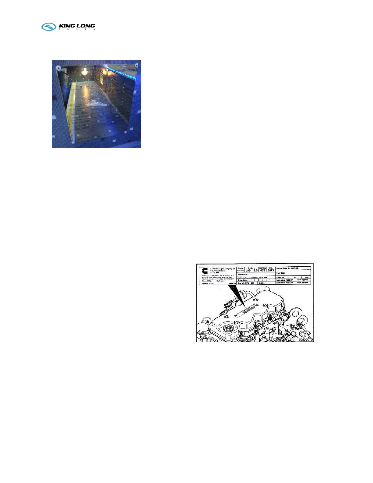
Engine data plate
The engine data plate is on top surface or salient top
position of the engine, whose position may be various
according to different engine manufacturing plant.
The engine number is stamped on the left or right
block of the engine, whose position may be various
according to different engine manufacturing plant.
Product quality assurance
We make breaking-in maintenance of the rolling-out new vehicles in their initial driving mileage of
5000 km. Users should make proper operation and maintenance strictly according to relevant
regulations in the instruction book. Please refer to “workshop manual” for product quality assurance
and abide by related specification.

Technical parameter and complete vehicle description
- 9 -
Technical document
The instruction book is used combined to the following specification:
Engine operation instruction or service manual
Transmission operation manual
CAN BUS Instrument system instruction book
ABS anti-braking system instruction book
Air conditioner instruction book
Heater instruction book
Monitor instruction book
VCD/DVD instruction book
Note: the instruction book should be modified according to specific configuration of vehicle.

Technical parameter and complete vehicle description
- 10 -
Body Structure
1. Structural style
Semi-integral body structure
2. Structure
The bodywork structure adopts closed girder construction of five major assembly parts, which are
combined welded by rectangle steel pipes with advantages of strong structural stiffness, torsion
resistance and bending resistance as well as relatively simple craftwork. Main components of skeleton
have been performed anticorrosion treatment to ensure steady adhesion of coating and strong capacity
of antirust and corrosion-proof.
3. Interior trim
The interior adopts flexible design and the floor adopts steel plate/wood block composite construction,
and covered with anti-slip and antifriction leather with favorable sound insulation value.
4. Windows
The front windshield is the hyperboloid triplex glass fixed by the gluing; the rear windshields are the
hardened glass fixed by the gluing; the side windows are close cycle window which are made of
hardened glass. The driver’s window is fixed with sliding window.
5. Baggage compartment
The baggage compartment adopts transverse run-through design, and they are all made of aluminum.
6. Seat
Driver’s seat: Q15-2 type , adjustable seat with high backrest and three-points style seat belts.
Passenger seats: KE-1 high backrest, adjustable type, the all seats are equipped with 3 points style
seat belts, pedal plate.
7. Interior accessory device
The vehicle is equipped with electronic clock, sunshade, safety hammer, emergency escaping window,
curtain and luxury bilateral K-1 type luggage rack,guiding seat,reversal monitor, Vehicle traveling data
recorder ,reading lamp, toilet, drinking trough, color TV, DVD system, LCD, guide mike .etc.
8. Air-conditioning system
Cooling system: KING LONG top mounted dependent air-conditioning system.
Defroster: King Long cooling /heating defrosting device
Heating system: Webasto heating system.
9. Door
The door adopts the full aluminum remote control out-swing pneumatic doors.
The out-swing door adopts the advanced electrically aerodynamic theory design, with the motion of
opening and closing placidly、agile、safe、lock credible and anti-clamp function.
A. Basic function
a. There are two electrically switches, the interior one is trigger touch-tone, which located on the
dashboard of the front right side of the driver, the outside one is a remote control switch. , both switches
can control the door.
b. When the circuit is in OFF position , the emergency switch can be used in the interior, the emergency
switch of the door is located on the lower right side of the entrance of the door , Please rotate the switch
and throw open the door in emergency.
c. Commonly the door is closed, when touch off any electrically switch, the door would move placidly
at a certain velocity, along with it, the step-lamp lights .when touch off the switch again , the door
would return placidly at a certain velocity, after the door returned , the step-lamp goes out.

Technical parameter and complete vehicle description
- 11 -
1 B. Hint: Tyre TPMS
a. The door remote control acts only when the parking brake is on the parking gear.
b. The door could only be opened when the external mechanical lock isn't locked up.
c. In order to avoid impact, make sure that the door is completed closed or opened, before you make the
next door switch operation.
Note: Deployment on the vehicle may be different with the above description because of different
deploying requirement of the clients.
Schematic illustration of the driver zone
1 Power charging outlet
2 Air-conditioner control panel
3 Radiator operation panel
4 Parking brake handle
5 Heater switch
6 Wiper operation handle
7 Mirrors operation button
8 Rocker switch
9 Steering wheel
10 Combination instrument
11 Light control lever
12 TPMS indication panel
13 Fire extinguisher pushbutton switch
14 Gearshift lever
15 Reversal monitor
16 Rocker switch
5
6
14
11
10
9
8
7
1
2
3
4
15 13 12
16
Technical parameter and complete vehicle description
I-1
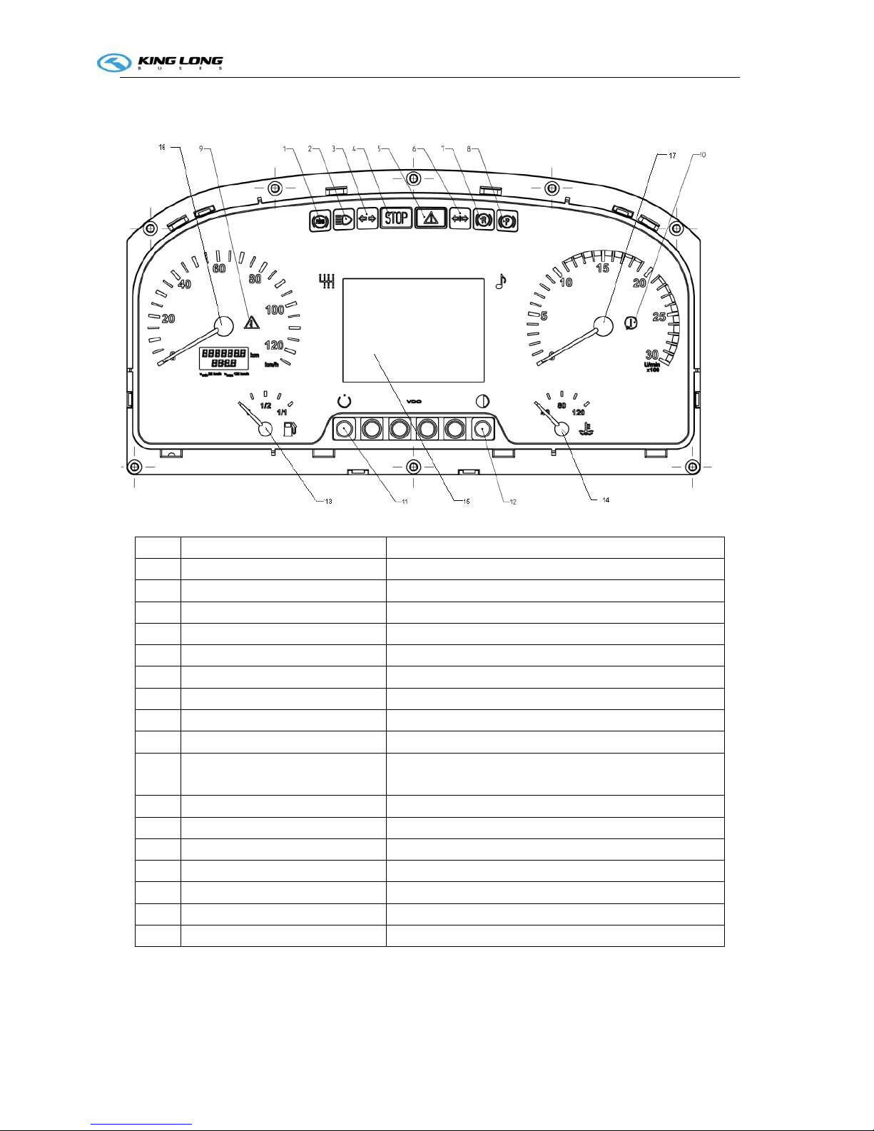
Instruction of instrument (VDO Edition)
No. Function Description
1 ABS indicator ABS work/warning
2 High beam indicator When High beam is switched on
3 Left turning indicator When Left turning/hazard switch is turned on
4 Severe Error When the electrical system has severe error. (see1.1 )
5 General Error When the electrical system has general warning. (see1.2)
6 Right turning indicator When Right turning/hazard switch is turned on
7 Retarder indicator Retarder work/warning
8 Parking brake
9 DTCO warning communication error or without drivers card
10 Engine Revolution speed too
high
Need to change the gear or slow down the bus
11 Trip distance reset button Set trip distance to 0
12 LCD illumination adjust button Press the button to adjust the illumination of LCD
13 Fuel level gauge The fuel remain
14 Coolant temperature gauge Temperature of engine coolant
15 LCD display
16 Speedometer Current vehicle speed
17 Odometer Current engine speed
Technical parameter and complete vehicle description
I-2
1.1 Severe error conditions
EDC red lamp; ECAS red lamp; EBS red lamp; coolant level low; battery not charging (after engine
starts); worn brake shoes; brake circuit 1/2 pressure low; coolant temperature high; catalyst level low;
engine cabin temperature high; oil pressure low (after engine starts).
1.2 General error conditions
Hammer not at right position; ASR error; air filter block; ECAS amber lamp; EBS amber lamp; rear flap
open; toilet water level low; steering oil level low; steering oil pressure low; fuel level low; DM1 error; light
error; communication error.
2 LCD Display
Press the page switch button, the pages will be displayed by the following sequence. Detailed
description is listed as below:
2.3 Driving Information
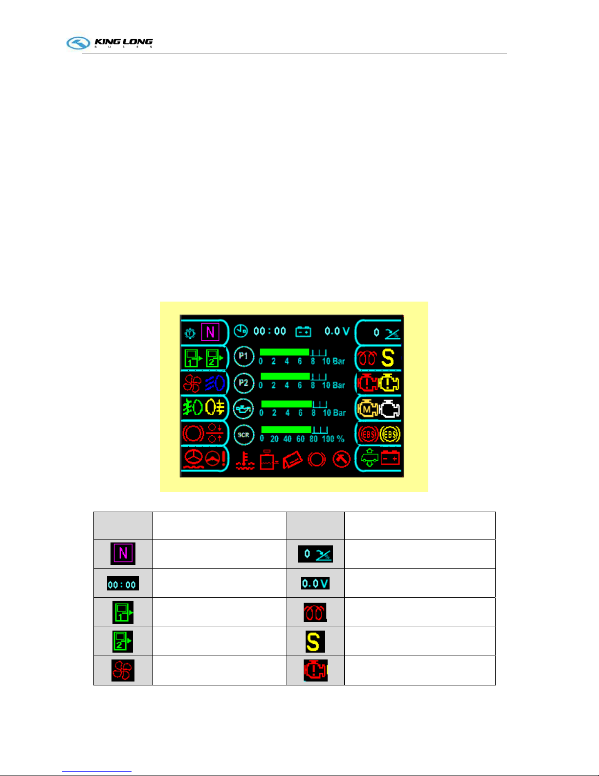
When the bus is running, this page will show (Figure-1 ):
Figure-1 driving information
pictogram comments pictogram comments
Gear info (see 2.1.1)
Acceleration pedal position
Current time (see 2.1.2)
System voltage (see 2.1.3)
Front door status (see2.1.7)
Preheating indicator
Mid door status (see 2.1.7)
Passenger service/request from
cabin(see 2.1.9)
Fluid fan error
Engine red lamp error
Technical parameter and complete vehicle description
I-3
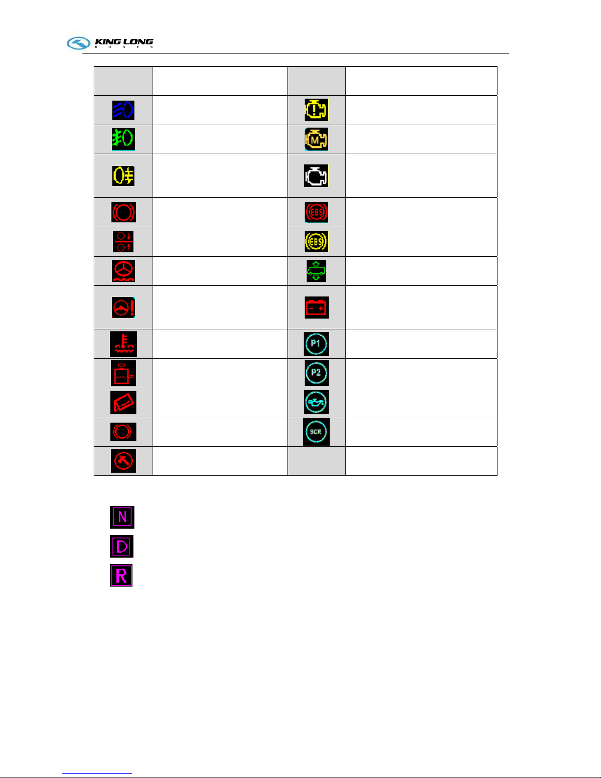
pictogram comments pictogram comments
Low beam working
Engine amber lamp error
Front fog light working
Engine Malfunction
Rear fog light working
Engine wait to start (do not start
the engine until this symbol
disappear)
Brake light working
EBS red lamp warning
Lift-axle lock
EBS amber lamp warning
Steering oil level low
ECAS status (see2.1.8)
Steering oil pressure low
Battery not charging (indicate
charging error if this symbol still
exist after engine starts)
Coolant temperature high
(>=98°C)
The bar shows brake circuit 1
pressure
Coolant level low
The bar shows brake circuit 2
pressure
Rear flap open (can not start the
engine)
The bar shows engine oil pressure
Worn brake shoes
The bar shows SCR remain
Hammer not at right position
Function description
2.3.1 Transmission gear Display:
:current gear is "neutral";
:current gear is "forward";
:current gear is "reverse";
2.3.2 Time:
This information comes from DTCO.
2.3.3 System voltage:
This value shows the battery voltage when generator is not working; and shows the voltage by
generator after engine starts.
Technical parameter and complete vehicle description
I-4
2.3.4 Acceleration pedal position:
Range: 0 – 100 %。
2.3.5 Oil pressure:
This information comes from engine ECU. Before engine starts, the value is 0.
2.3.6 Brake system pressure:
Brake circuits 1 refers to the front brake system pressure.
Brake circuits 2 refers to the rear brake system pressure.
The symbol becomes red if the pressure is too low or if sensor is open-load.
2.3.7 Door status:
: green; means door is open
: yellow; means the cap on the emergency switch is open (either inside or outside)
: brown; means the knob in the emergency switch is moving
2.3.8 ECAS status
:ECAS lift :kneeling
:ECAS general error :ECAS severe error
2.3.9 Service request
:Passenger service request :Request from cabin
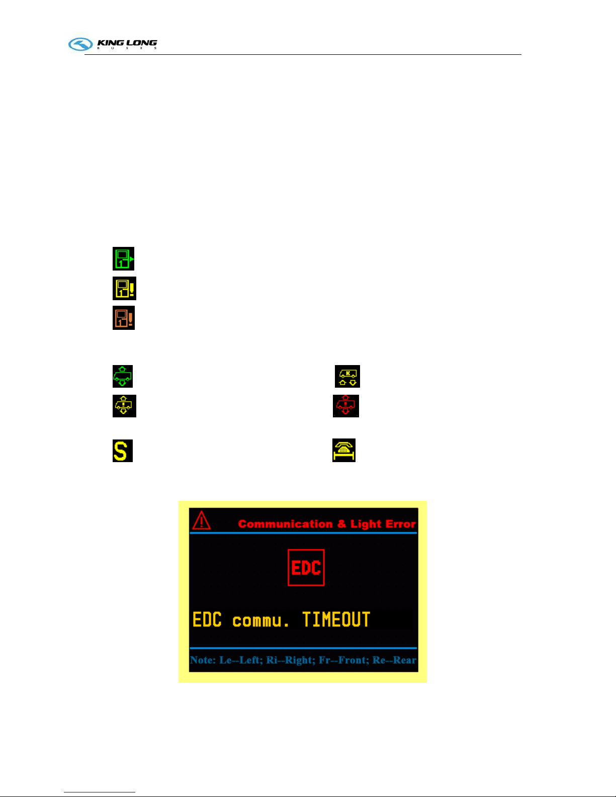
2.2 Error display Page:
Figure -2 text error information
Technical parameter and complete vehicle description
I-5
If there is error exists, this page will show after driving information page when you press the page
change button.
Description:
Pictogram
:object name;
Text: detailed description of the error;
Errors can be displayed in this page:
Communication Error: EDC, EBS, TCO, AC, Front node, Top node, Cabin node, Rear node;
Light Error: high-beam, low-beam, reverse light, front fog light, rear fog light, brake light, turning
light
Other Error: brake circuit pressure open-load, fuel-sensor open-load, Engine cabin too hot, worn
brake shoes (1-6), fuel level low, water in toilet level low, air filter block,
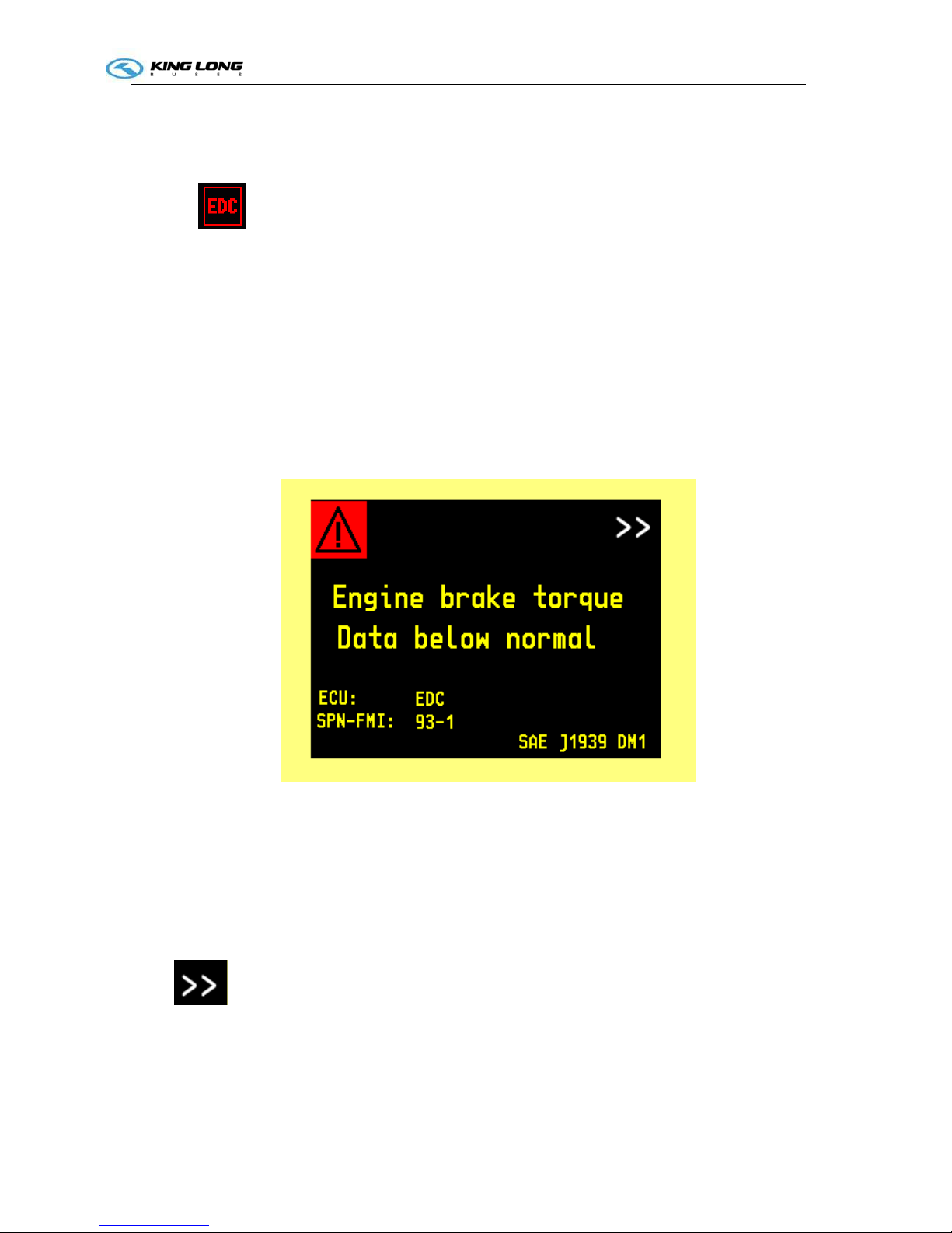
2.3 DM1 Diagnosis Information
Figure -3 DM1 display page
This page will show when some ECU sends out DM1 message. The diagnosed ECU must support
CAN diagnosis, and provides SPN-FMI code.
Line1: the object that has error (from SPN).
Line2: Error status (from FMI)
Line ECU: name of the ECU that sends the message (i.e. EDC, EBS, AC)
Line SPN-FMI: the SPN and FMI combination
: means this error is not the last one
Other contents are fixed
Technical parameter and complete vehicle description
I-6
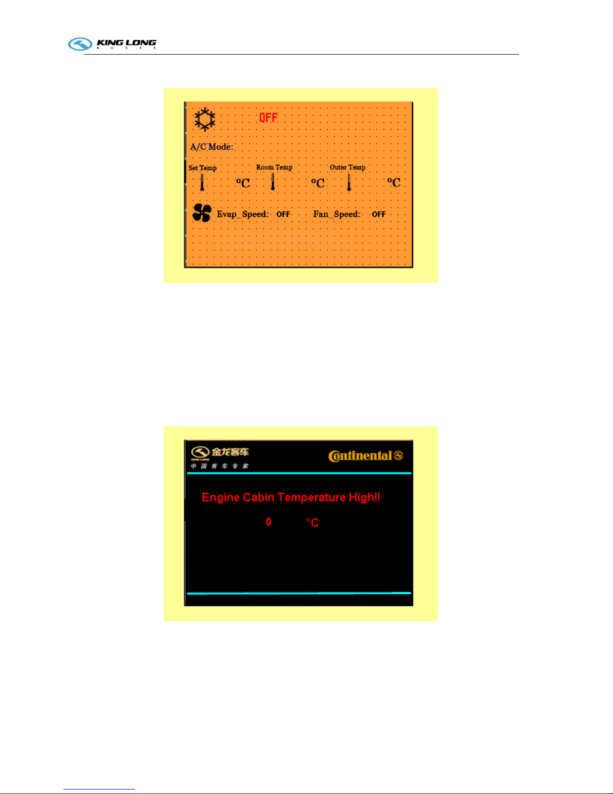
2.4 Air conditioner status
This page will appear is air conditioner is working and the communication is right.
A/C mode include: ventilation; heating; cooling; demist/defrost; auto mode; off
Set temp: the temperature currently set to be;
Room temp: the real ambient temperature in the bus;
Outer temp: outside temperature;
Evap_speed: OFF; High; Mid; Low
Fan_speed: OFF; High; Low
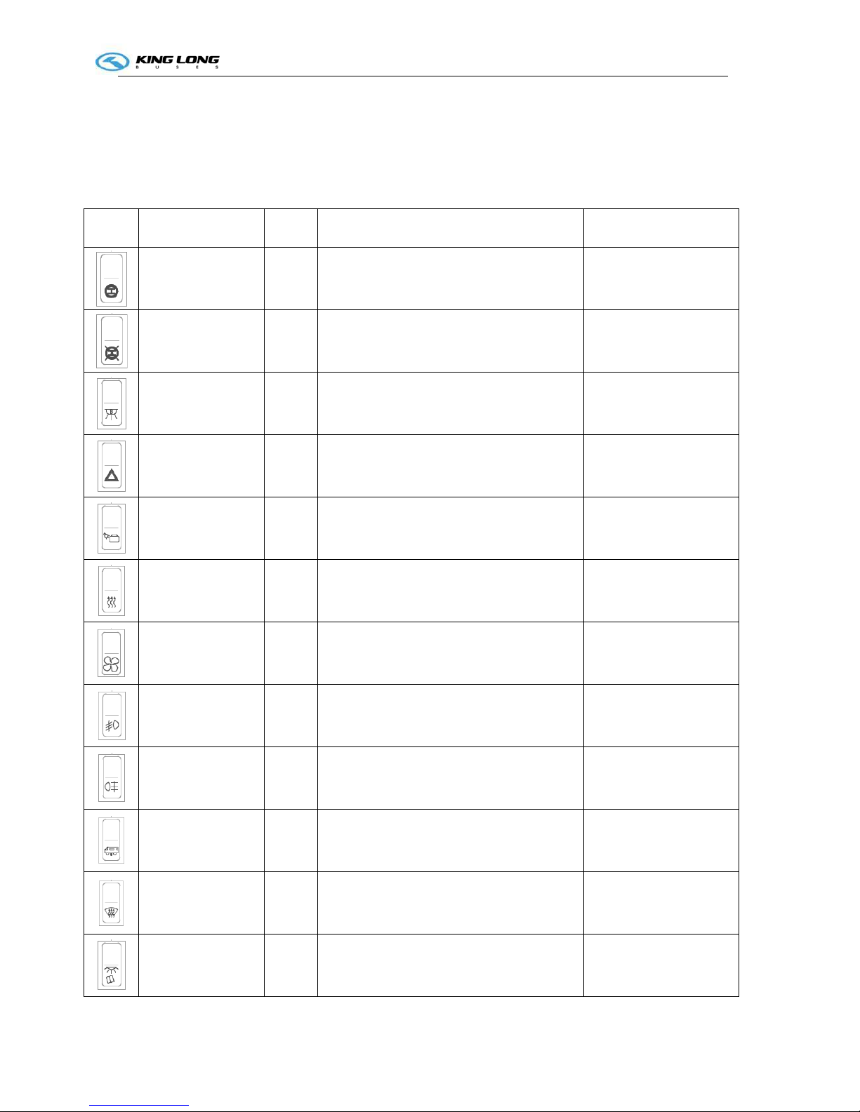
2.5 Engine Cabin Temperature high warning page
If engine cabin temperature is higher than 85°C, this page will appear automatically. The temperature
will show on the page. The driver need to press the page change button to switch to the driving page

Technical parameter and complete vehicle description
I-7
2.6 Beeper warning conditions
Brake circuit 1 pressure low
Brake circuit 2 pressure low
Coolant level low
Hammer not at right position
Engine cabin temperature high
Oil pressure low (after engine running)
Service request
Left turning
Right turning.
Technical parameter and complete vehicle description
SI-1
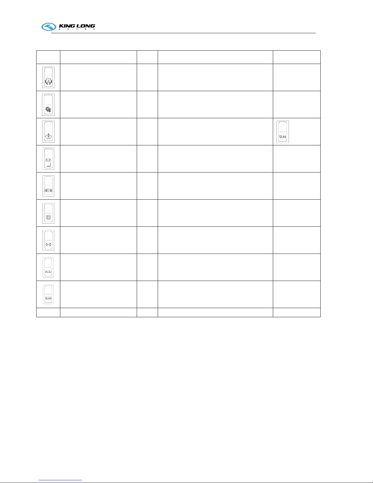
Illustration of switch and indicator
Number of switches and indicators and position may vary with vehicle model, please consult the flowing
sheet and use correctly according to actual condition of vehicle.
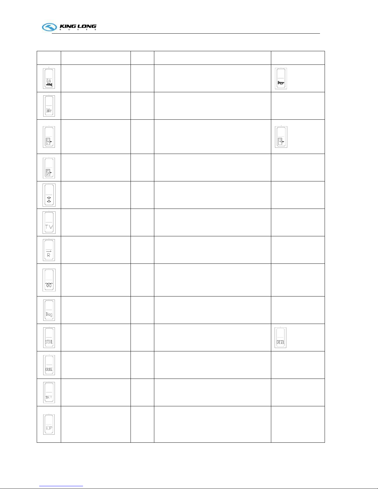
Switch
Name Color Function Notes
Retarder Green
Pressed on top: retarder is turned ON
Pressed on bottom: retarder is turned OFF
Retarder turn off
switch
Pressed on top: retarder is turned OFF
Pressed on bottom: retarder is turned ON
Daylight lamp
Green
Pressed on top: interior lighting ON,
Pressed on bottom: interior lighting OFF
Hazard lamp Red
when the vehicle have a screw loose, switch
it on, the whole vehicle lamps light
Luggage
compartment lamp
Green
Pressed on top: lamp lights ,
Pressed on bottom: lamp goes out
Compulsory
radiator
Green
Pressed on top: radiator working ;
Pressed on bottom: to turn it off
only use this button
when vehicle is stopping
Ventilator
Green
Pressed on top: ventilator is active,
Pressed on bottom: ventilator is turned off
Front fog lamp
Green
Pressed on top: front fog lamps ON,
Pressed on bottom: front fog lamps OFF
Rear fog lamp
Yellow
Pressed on top: rear fog lamps ON,
Pressed on bottom: rear fog lamps OFF
Vehicle raise/lower
Green
Pressed on top: vehicle raise,
Pressed on bottom: vehicle lower
only use this button
when vehicle is stopping
Defroster
Yellow
Pressed on top: windscreen heater ON,
windscreen heater OFF
Reading lamp
Green
Pressed on top: reading lamp ON, Pressed on
bottom: reading lamp OFF
Technical parameter and complete vehicle description
SI-2
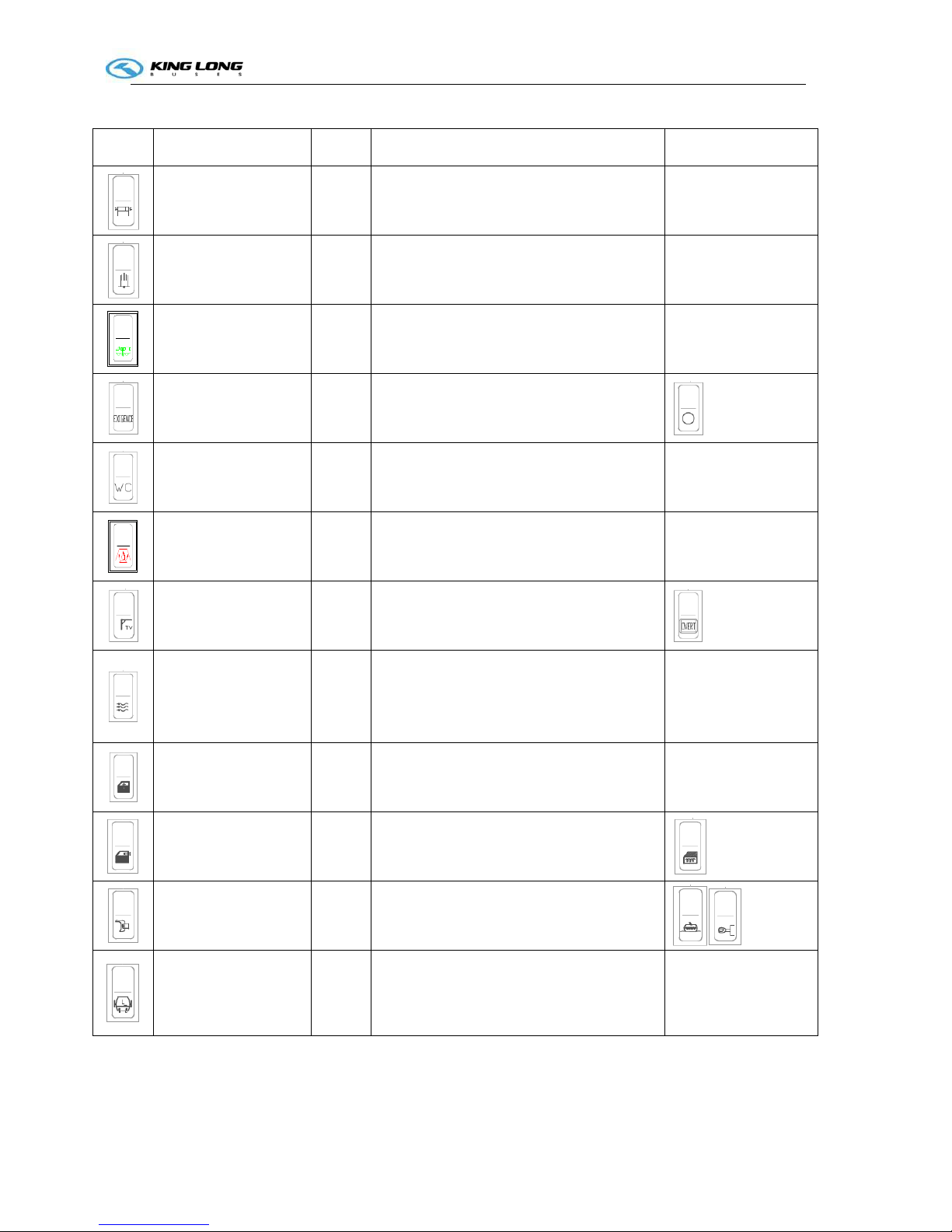
Switch Name Color Function Notes
horn Green
Pressed on top: air horn is active, Pressed on
bottom: electric horn is active
Engine idle Green
Pressed on top: engine idle speed raise,
Pressed on bottom: engine idle speed lower
adjust engine
speed
Front passenger door Green
press button once to open front passenger
door;
press button again to close
Rear passenger door
Green
press button once to open passenger door;
press button again to close
Electric curtain Green
Pressed on top: to raise curtain;
Pressed on bottom: to lower curtain
TV
green
Pressed on top: TV is turned ON,
Pressed on bottom: TV is turned OFF
Reversal monitor
Green
Pressed on top: reversal monitor turned ON,
Pressed on bottom: reversal monitories
turned OFF
Rearview mirror
defrost(preheating)
Yellow
Pressed on top: preheating ON,
Pressed on bottom: preheating OFF
Diagnose
Green
press this button to make a diagnosis of
engine, when engine indicate trouble
Disinfect Green
Pressed on top: disinfection turned ON,
Pressed on bottom: disinfection
turned OFF
Cruise
Green
Pressed on top: cruise function is active,
Pressed on bottom: cruise function isn't
active
we advise clients
not to use this
switch
Cruise setting
Green cruise setting
we advise clients
not to use this
switch
Emergency time-delay
parking
Red
Pressed on top: Emergency time-delay
parking function is active,
Pressed on bottom: Emergency time-delay
parking function isn't active
only used when
engine failure
Technical parameter and complete vehicle description
SI-3
Switch Name Color Function Notes
Exterior guidepost
Red
Pressed on top: turn on guidepost lamp;
Pressed on bottom: turn off guidepost lamp
Assistant brake
Yellow
Pressed on top: turn on assistant brake;
Pressed on bottom: to turn it off
only switch on when
vehicle need park
Vehicle level reset Green Pressed on top: vehicle level reset
Emergency power
Red
Pressed on top: emergency power turned ON
Pressed on bottom: emergency power is
turned OFF
Toilet power switch
Green
Pressed on top: Toilet power is turned ON,
Pressed on bottom: Toilet power is turned
OFF
Heater switch
Red
Pressed on top: to turn on heater ;
Pressed on bottom: to turn it off
TV overturn switch Green
Pressed on top: expand the TV,
Pressed on bottom: collapse the TV
Fresh air switch Green
Pressed on top: turn on the changing fresh
air function;
Pressed on bottom: turn off the changing
fresh air function.
Electric driver window
switch
Green
Pressed on top: the glass getting up;
Pressed on bottom: the glass getting down.
Electric driver window
defrosting switch
Yellow
Pressed on top: turn on defrosting function;
Pressed on bottom: turn off defrosting
function.
Rearview mirror
defrosting switch
Pressed on top: turn on defrosting function;
Pressed on bottom: turn off the defrosting
function.
Left side bin gate Green
Pressed on top: open the left side bin gate;
Pressed on bottom: close the left side bin
gate.
Technical parameter and complete vehicle description
SI-4
Switch Name Color Function Notes
Right side bin gate Green
Pressed on top: open the right side bin gate;
Pressed on bottom: close the right side bin
gate.
Powerful/abstemious
transfer switch
Pressed on top: turn on powerful function;
Pressed on bottom: turn off abstemious
function.
Electric sun blind Green
Pressed on top: the sun blind getting down;
Pressed on bottom: the sun blind getting up.
Driver seat lamp switch Green
Pressed on top: turn on the driver seat lamp;
Pressed on bottom: turn off the driver seat
lamp.
Kneeling switch Green
Pressed on top: turn on kneeling function;
Pressed on bottom: turn off kneeling
function.
Coin box switch Green
Pressed on top: open the coin box;
Pressed on bottom: turn off the coin box.
Turning lamp switch Green
Pressed on top: turn on the turning lamps;
Pressed on bottom: turn off the turning
lamps.
ACU unlock switch Green
Pressed on top: ACU unlock;
Pressed on bottom: ACU lock.
For articulate
plate only
Inner guidepost switch Green
Pressed on top: turn on the inner guidepost;
Pressed on bottom: turn off the inner
guidepost.
Technical parameter and complete vehicle description
SI-5
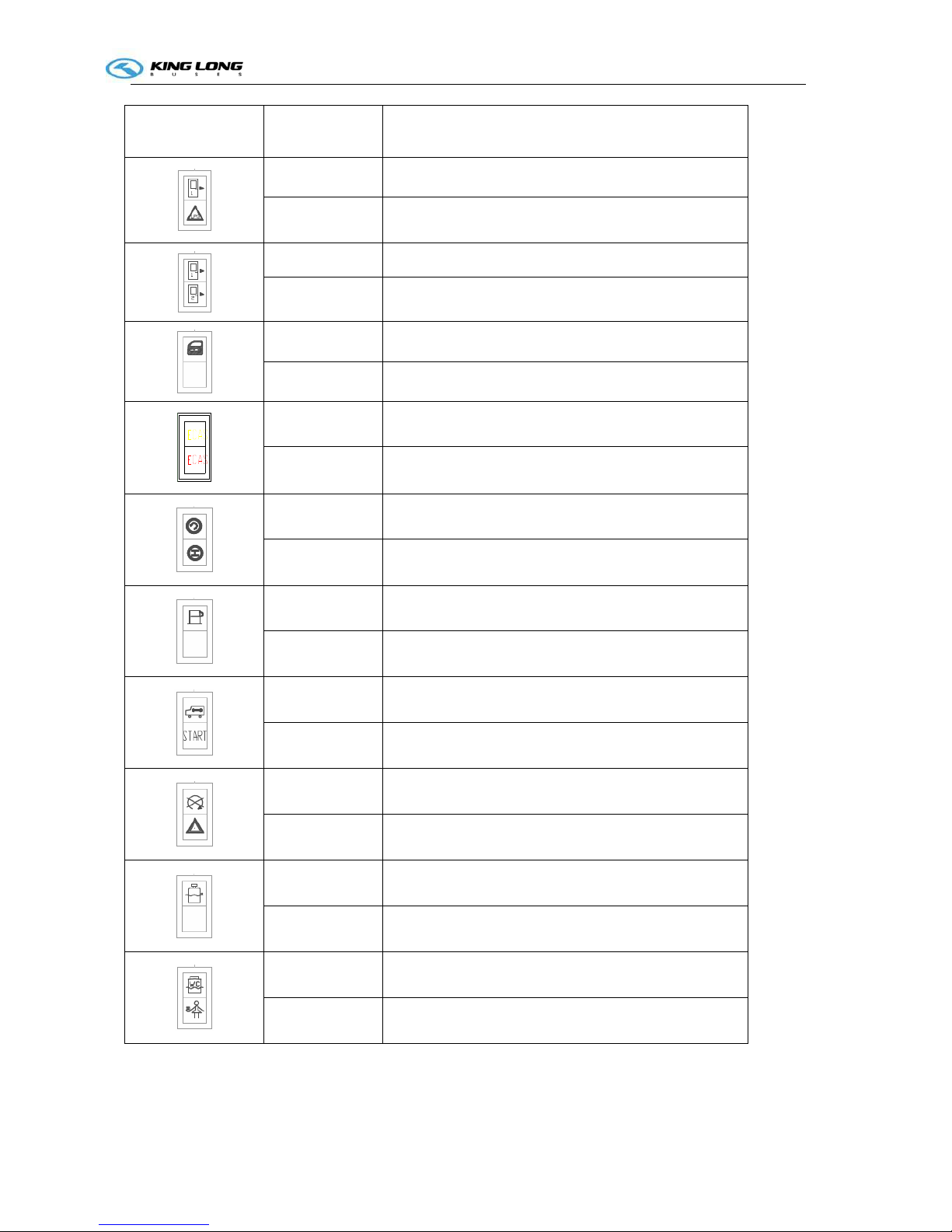
Indicator lamp
Color
Function
Red passenger door open indicating
Red natural gas leakage indicating
Red front passenger door open indicate
Red rear passenger door open indicating
Red exit has been open indicating
hollow plate
Yellow ECAS alarm indicating
Red ECAS fault indicating
Red gearbox fault warning indicating
Green retarder indicating
yellow Fuel filter seeper
Hollow plate
Yellow Maintain waiting
yellow Start
Red Stop
Yellow Alarm
Red Water level
hollow plate
Green WC
Red Service
Technical parameter and complete vehicle description
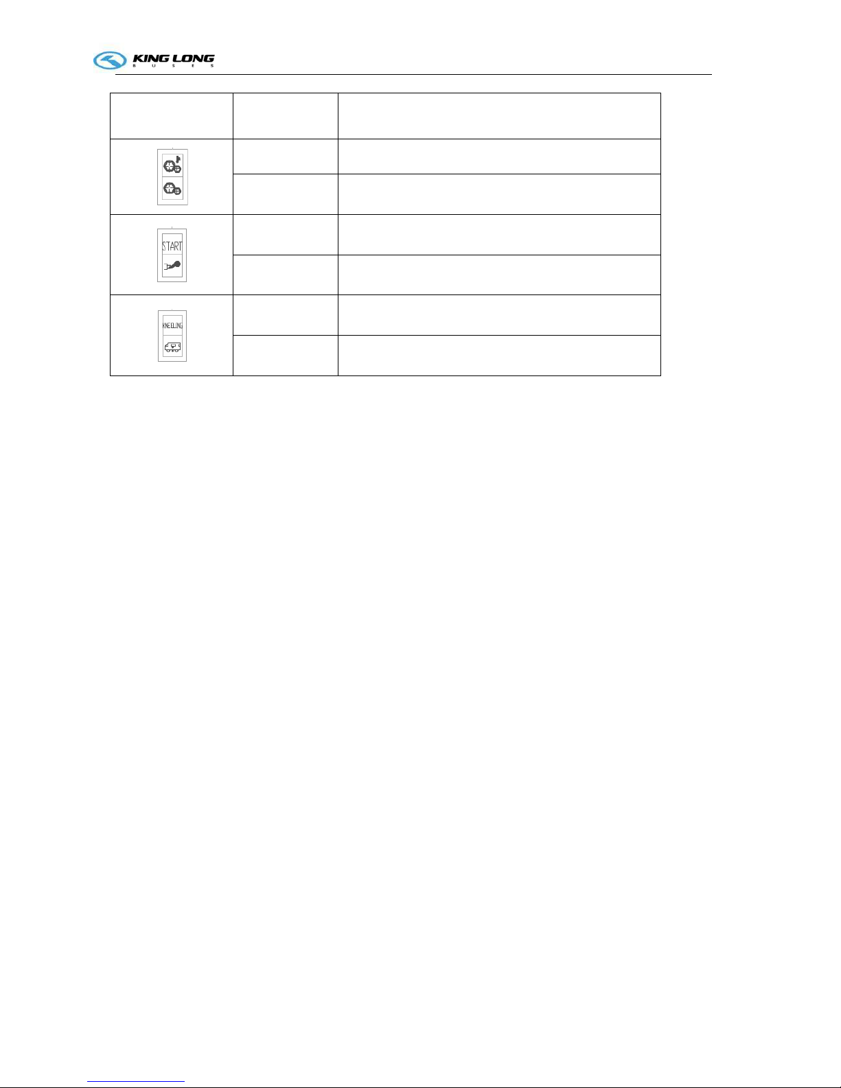
SI-6
Indicator lamp
Color
Function
Red Transmission oil temperature too high
Red Transmission fault
White Start-up waiting
Yellow Over emission
Yellow Kneeling lamp
Green Normal height
Technical parameter and complete vehicle description
P-A-1
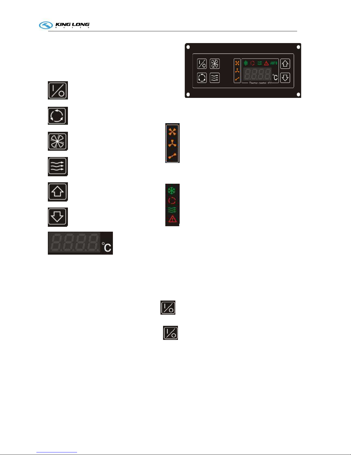
Air conditioner control panel (SK-17-1)
Air conditioner (KL-XIY-J)
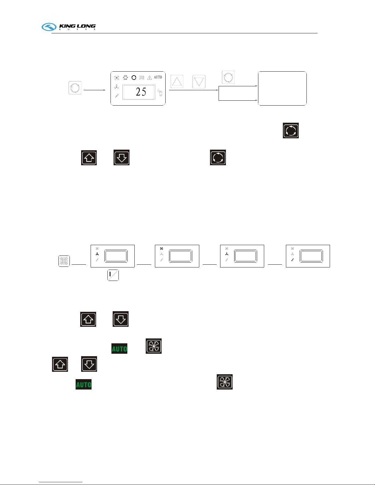
Control panel operation:
1) How to use the air conditioner
Start the engine⑴
turn ON the cooling switch⑵ , push
set the suitable temperature⑶ ——the setting temperature will be held automatically
turn OFF the cooling switch⑷ ,push for one second.
stop the unit⑸
2) Temperature setting
COOLING——The system begins to cool if the set temperature is lower than the
temperature inside the bus
——The system stops cooling if the set temperature is higher than (or equal to)
the temperature inside the bus
Indicator light introduction:
low air speed
midterm air speed
high air speed
Cooling
Setting Temp
Pressure alarm indicator
Fresh air
Select key introduction:
Power key
Select ensure key
Air speed select key
Fresh air select key
Up key
Down key
Temperature display
Technical parameter and complete vehicle description
P-A-2
3) Temperature controlling
For example: adjust the set temperature from 25 to ℃
20℃
AUT
O
2
5
Press once and
regulation
Press
again
display the setting temperature
Automatic setting
after 5 seconds
Displaying the
temperature inside
the bus from the
LCD screen
The lamp of setting the temperature will light up when pressing the button of . The
setting temperature will be displayed on the LCD screen. Adjust the temperature with the
button of and to 20 . Press the b℃ utton of after setting the temperature, the
setting temperature light is off. Otherwise, the LCD screen will display the temperature inside
the bus 5 seconds later.
Note:
the scope of setting temperature is from 15.0 to 40.0℃℃
the scope of displayed temperature is from -40.0 to 40.0℃℃
4) Flow rate selection
℃
2525
℃
When starting the switch, the wind flowrate will begain from the low level .
→
Press
four times
→
Press
three times
→
Press
twice
Press
once
→
℃
25
O
25
℃
5) Automatic flow rate selection
Press the and for 2 seconds then the unit will begin automatic flow rate selection,
it will change the flow rate depends on the air return temperature. Then the indication light at
the above right light . The flow selection is not work at the moment. Press the
and button at the same time for 2 seconds can stop the automatic flow rate selection
and the indicator light will stop and the air flow rate selection will recover.
6) Working conditions of the automatic flow rate selection
High air flow rate: The temperature of air-return inside the bus is higher than 26.5 ℃
(including 26.5 ).℃
Medium air flow rate: the temperature of air-return inside the bus is 24.5—26 .℃
Technical parameter and complete vehicle description
P-A-3
Low air flow rate: the temperature of air-return inside the bus is lower than 24 ℃
(including 24 ).℃
When switching air flow rate by different temperature, the switching confirm time is 30
seconds.
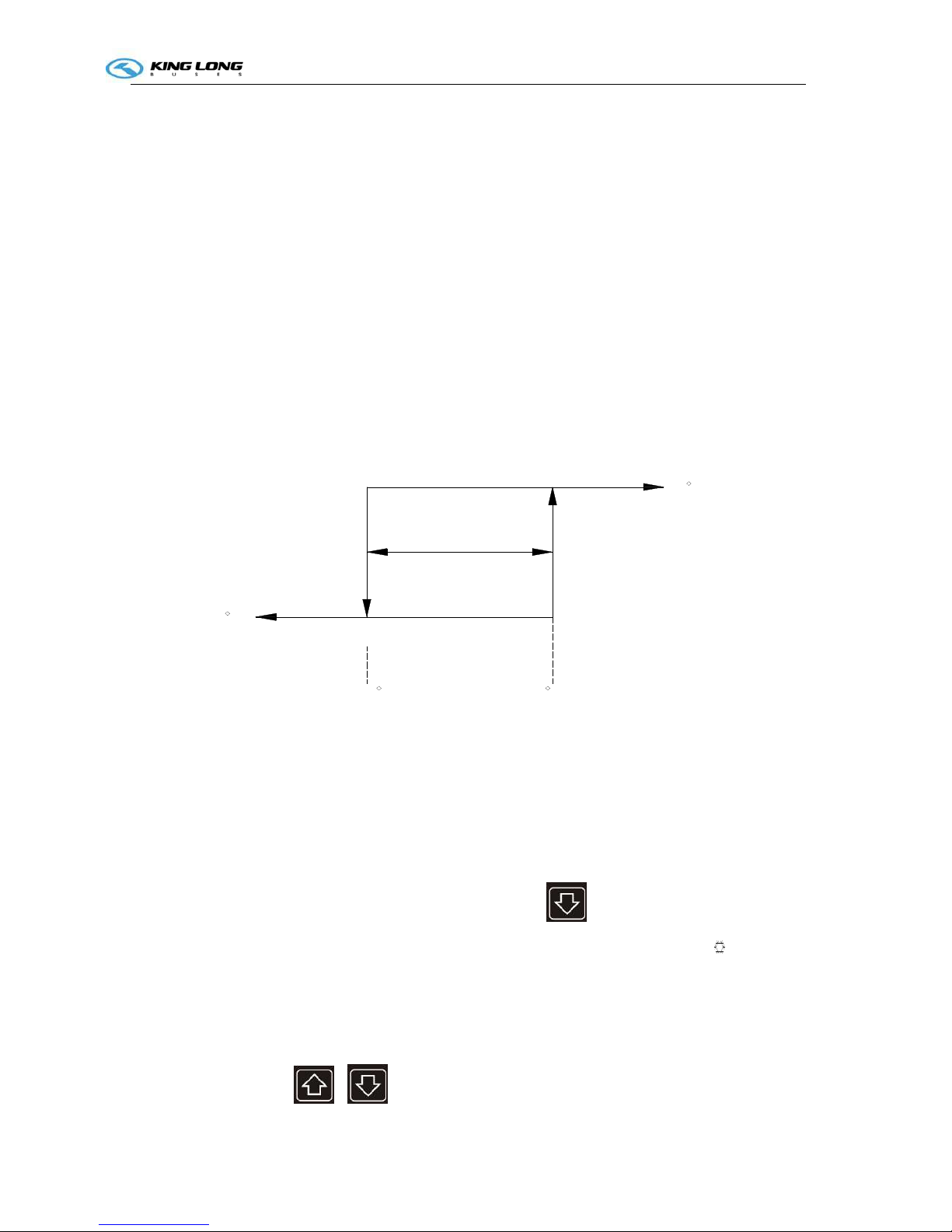
7) Temperature control method
Using ON/OFF mode:the temperature controlling precision (DIF)is 2℃,(FIX
SETTING)
For example: the temperature controlling precision(DIF)is 2℃,The setting temperature
is 25 .℃
When the bus inside temperature is 30 :℃
The cooling system will be stop (OFF) when the temperature reaching 25 .℃
The cooling system will be start (ON) for cooling (COOLING) when the temperature is
over 27 . The cooling℃ delay time is 10 seconds when it’s at the first starting, after this the
interval time is 30 seconds.
Temperature
cycle2° C
(- C)
Setting temperature25°
C
25 C
OFF cooling mode
27 C
(+ C)
on cooling mode
8) Strong cooling
This function of maintenance is used in the season which the air conditioner does not use(over
2 ins℃ ide of bus). The goal is provide the lubricant to the shaft sealing ring by the pressure of
the working compressor. Normally it works 10 minutes and once or twice every month.
9) Operation of strong cooling
When the temperature setting is15 and press the bu℃ tton for 5 seconds, the temperature
setting indicator 2 . After the strong cooling work for few seconds, the cooling℃ light
up. The temperature setting turn back to 22 when one cooling cycle finish. ℃
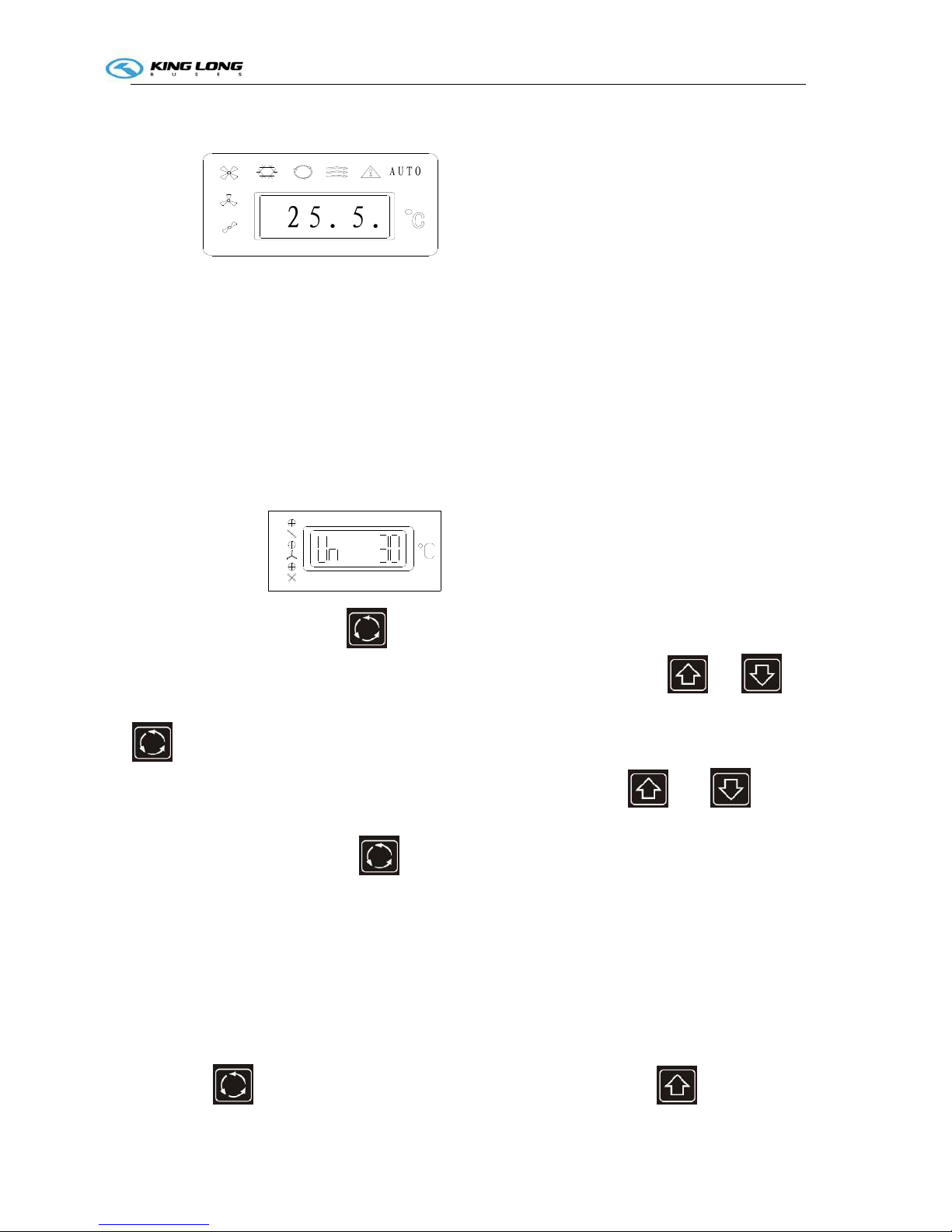
10)
Defrosting temperature
The LCD screen will display the defrosting temperature1 or defrosting temperature 2 by
pressing the button of
or .
Technical parameter and complete vehicle description
P-A-4
11) The part below the LCD screen will flash when the defrosting function working.
Display the defrosting temperature
2
5
.
5
.
AUT
O
Note:
The compressor (⑴ COMP) and the condenser (COND) fan will stop working and
the evaporate (EVA) fan will run normally when the system defrosting.
The operation of the defrosting is automatically Controlled. the defrosting operation ⑵
begins to work when the temperature of the sensor is(ON) at -1 and stops working (OFF) ℃
at 8 .℃
12) Set the fresh air vent function
The LCD screen will display the Vent open (Vn) and the
setting time when the button pressed for 5 seconds. The button pressed again to show
VF and the setting time. Adjust the setting time by pressing the button of and to
the setting time within 1—60min.(Generally the setting time is 10 minutes). Press the button
for the confirming of the time setting, or the system will confirm the setting time
automatically in 5 seconds. Adjust the setting time by the button and within
1—60min when the LCD screen display VF and the setting time.(Generally the setting time is
30 minutes). Press the button for the confirming of the time setting or the system will
confirm the setting time automatically after 5 seconds.
Note:
Restart the (VENT) switch to carry out the new procedures after the setting.
Otherwise, the previous setting will be carried out again.
Only one parameter can be set for each time.
13). check the power.
Press the
10 seconds, it shows the air conditioner voltage. Press the , it shows the
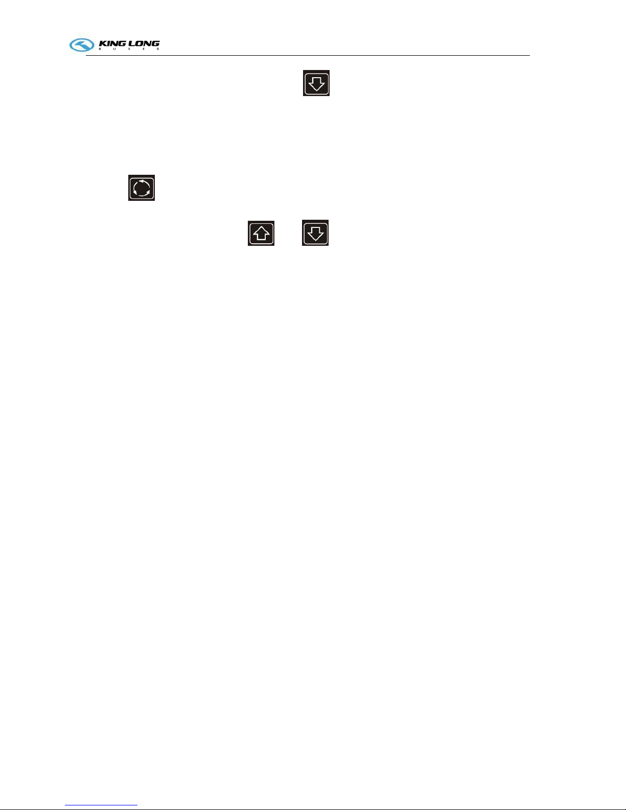
Technical parameter and complete vehicle description
P-A-1
red line voltage of control panel. Press the ,it shows the voltage of air conditioner
generator(when the air conditioner is without generator, it only shows the red line voltage of
control panel i.e. the voltage of vehicle generator.)If it isn't operation during this process, it will
show the air return temperature after 5 seconds.
14),check and cleanup time
Press the for 12 seconds, it shows the working time of air conditioner. During this
procss it isn’t operation. After 5 seconds, it shows the air return inlet temperature. When the air
conditioner is working, press the and for 2 seconds at the same time. It can be
cleanup the time as 0.
Note:
the working time of air conditioner ,it can be calculated the time as hours since the low flow
rate is beginning. That can be added up every working time of turn off the unit and control
panel power off . It also can check and clean up the working time at any alarm condition.
Technical parameter and complete vehicle description
P-H-1
Pre-heater Operation (Webasto)
1. General
The standard digital timer enables you to preset the
start of the heater operation up to 7 days in advance.
It is possible to program 3 different starting times,
only one of which can be activated.
The standard digital timer features a wakeup alarm
function.
When the ignition switched on, the timer displays
the current time and the day of the week.
When the heater is switched on, the display and
the buttons are illuminated.
After the power supply has been connected,
all symbols on the display will flash.
The current time and weekday must be set.
2. Operation
The timer can be operated in that all flashing symbols
can be adjusted by means of the 10 and 9 buttons.
If the buttons are not pressed within 5 seconds,
the time displayed will be stored.
If the 10 and 9 buttons are pressed for more than
2 seconds, the fast time-setting mode is activated.
If the ignition is switched off while the heater is operating in the continuous mode, the
remaining operating time of 15 minutes is displayed and the heater continues to operate for this
period of time.
3. Switch the heater on
Manually: by pressing the button 8 (continuous heating mode)
Automatically: by programming the heater starting time
4. Switch the heater off
Manually: by pressing the button 8
Automatically: after the programmed operating time has elapsed.
With the heater running: by programming the remaining operating time
5. Setting time/day of the week
Press the 6 button for more than 2 seconds-time of the day if flashing-and set the clock using
the 9 and 10 buttons. Day of the week is flashing – adjust the day of the week.
6. Viewing the time
With the ignition switched off: press the 6 button.
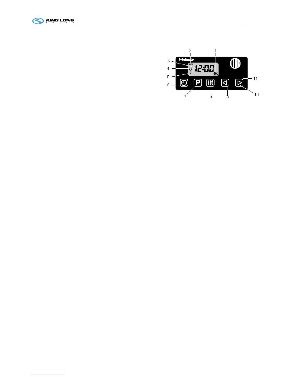
7. Programming heater starting time:
Standard Timer
1. heater “on” indicator
2. day of the week
3.
time display
4.
memory location
5.
alarm indicator
6.
time
7.
program selection
8.
instant heating
9.
reverse
10.
forward
11. panel
 Loading...