

King Long XMQ6127 series Operating Manual
- 1 -
OPERATION MANUAL
User’s Guide
King-Long XMQ6127 series tourist bus
Xiamen King Long United Automotive Industry Co., Ltd.

Foreword
- 2 -
FOREWORD
King-Long XMQ6127 series tourist bus keeps features of superior economy,
security and comfort. It has stable performance, strong power, luxury interior
trimming and high speed, which could meet applications of passenger inter-city
transportation, touring and business affairs, etc.
As for the specifications introduced in relate to information of the driving
and operation, service and maintenance of the XMQ6127 series tourist bus,
please read them carefully and make proper operation, maintenance and repair so
as to ensure it in good condition. Special hint: without authorization of Xiamen
King Long United Automotive Industry Co., Ltd, never modify the electrical
deployment of the whole vehicle, and should not lap the power supply line in
disorder. Improper usage and repair may have a strong impact on service
performance of the complete vehicle, and thus the manufacturer , Xiamen King
Long United Automotive Industry Co., Ltd. will not takes the responsibility for
the damages caused by them.
Any problem in service, please contact our special maintenance network or
after-sales department. We will ensure timely and complete maintenance as well
as original parts supply.
In order to satisfy all kinds of different demand of the consumers, we strive
to improve the quality of the product continuously to optimize our products. We
should not give any further notice for any modification of the product in advance .
The contents on the instruction book can only be used as reference. If there are
facts not comply with the manual, will be subject to the actual state of the
products because for some device and items, the vehicle will be finally equipped
only if they have been taken as optional configurations.
Final interpretive right of the instruction book belongs to the engineering
academy of Xiamen King Long United Automotive Industry Co., Ltd.
Xiamen King Long United Automotive Industry Co., Ltd.
MAY. 2016

Contents
- 3 -
Contents
Vehicle picture--------------------------------------------------------------------------------------------------------1
Foreword---------------------------------------------------------------------------------------------------------------2
Contents
Contents--------------------------------------------------------------------------------------------------------------3-6
Technical parameters and complete vehicle description
Technical parameters ------------------------------------------------------------------------------------------------7
Introduction to data plate--------------------------------------------------------------------------------------------8
Product quality assurance -------------------------------------------------------------------------------------------9
Technical document -------------------------------------------------------------------------------------------------9
Vehicle body structure----------------------------------------------------------------------------------------------10
Schematic illustration of the driver zone-------------------------------------------------------------------------11
Operation Instruction
Instrument instruction--------------------------------------------------------------------------------------------CI-1
Illustration of switch and indicator s--------------------------------------------------------------------------SI-1-3
Air conditioner control panel-----------------------------------------------------------------------------------P-A-1
Heating Operation---------------------------------------------------------------------------------------------P-H-1-3
Gearbox operation ----------------------------------------------------------------------------------------------O-G-1
ABS instruction------------------------------------------------------------------------------------------------O-AB-1
ECAS instruction----------------------------------------------------------------------------------------------O-EC-1
Toilet operation-----------------------------------------------------------------------------------------------O-T-1-4
Open or close the passenger door---------------------------------------------------------------------------O-K-1-2
Adjustment of the driver's seat----------------------------------------------------------------------------------OI-1
Horn button---------------------------------------------------------------------------------------------------------OI-2
Adjustment of the steering wheel-------------------------------------------------------------------------------OI-3
Ignition switch----------------------------------------------------------------------------------------------------OI-4
Lamplight operating handles------------------------------------------------------------------------------------OI-5
Wiper operating handle-------------------------------------------------------------------------------------------OI-6
Passenger control panel-------------------------------------------------------------------------------------------OI-8
Safety hatch--------------------------------------------------------------------------------------------------------OI-9

Contents
- 4 -
Safety hammer---------------------------------------------------------------------------------------------------OI-10
CAN module location & function description------------------------------------------------------------O-E-1-2
Switch control box----------------------------------------------------------------------------------------------O-E-3
Vehicle starting and driving
Check oil level of the engine--------------------------------------------------------------------------------------S-1
Check level of the coolant-----------------------------------------------------------------------------------------S-2
Check fuel pre-filter with water separator-----------------------------------------------------------------------S-3
Check fuel level-----------------------------------------------------------------------------------------------------S-4
Check vehicle lighting, intermittent lights and brake lights---------------------------------------------------S-5
Check the level of AdBlue and the daily maintenance of SCR system--------------------------------------S-7
Drain water in air tank---------------------------------------------------------------------------------------------S-8
Check engine oil pressure------------------------------------------------------------------------------------------S-9
Check Pneumatic pressure---------------------------------------------------------------------------------------S-10
Check Tachometer working order-------------------------------------------------------------------------------S-11
Steering wheel play-----------------------------------------------------------------------------------------------S-12
Check tire for abrasion and pressure and tire nut for fixture------------------------------------------------S-13
Air cleaner----------------------------------------------------------------------------------------------------------S-14
General leakages (water, oil, fluids and fuel) -----------------------------------------------------------------S-15
Fastening and state of seat belts---------------------------------------------------------------------------------S-16
Check emergency devices and driver’s tools (fire extinguisher) -------------------------------------------S-17
Windshield wipers and conditions of wiper blades and arms-----------------------------------------------S-18
Electrical rearview mirror----------------------------------------------------------------------------------------S-19
Power steering system--------------------------------------------------------------------------------------------S-20
General state and tension of drive belts------------------------------------------------------------------------S-22
Check level of battery electrolyte-------------------------------------------------------------------------------S-24
Procedures for engine start up-----------------------------------------------------------------------------------S-25
Engine shut down-------------------------------------------------------------------------------------------------S-26
Engine start up and shut down in the engine compartment--------------------------------------------------S-27
Starting the vehicle------------------------------------------------------------------------------------------------S-28
Parking the vehicle------------------------------------------------------------------------------------------------S-29

Contents
- 5 -
Vehicle maintenance and service
General knowledge------------------------------------------------------------------------------------------------M-1
Maintenance of engine and chassis subassembly--------------------------------------------------------------M-1
Body maintenance ------------------------------------------------------------------------------------------------M-1
ABS/EBS system maintenance and service -------------------------------------------------------------------M-1
Electrical system maintenance and notices --------------------------------------------------------------------M-2
Tire transposition--------------------------------------------------------------------------------------------------M-2
Adjustment of the brake pedal freeplay------------------------------------------------------------------------ M-3
Bus cleaning--------------------------------------------------------------------------------------------------------M-3
Cleaning air filter --------------------------------------------------------------------------------------------------M-4
Cleaning outside of radiator -------------------------------------------------------------------------------------M-5
Coolant specification ---------------------------------------------------------------------------------------------M-5
Oil specification recommendation of the fuel and the lubricant---------------------------------------------M-6
Breaking-in of a new vehicle--------------------------------------------------------------------------------M-9-10
Daily Maintenance Operation----------------------------------------------------------------------------------M-11
Maintenance per 5000km---------------------------------------------------------------------------------M12-M14
Maintenance per 10000km--------------------------------------------------------------------------------------M-15
Maintenance per 20000km----------------------------------------------------------------------------------M-16-18
Maintenance per 40000km -----------------------------------------------------------------------------------M-19
Maintenance per 80000km ------------------------------------------------------------------------------M-19
Maintenance more than 80000km------------------------------------------------------------------------------M-20
Maintenance period chart-----------------------------------------------------------------------------------M-21-28
Common trouble and its eliminating method
Engine Common trouble and elimination ---------------------------------------------------------------C-1
Propeller shaft------------------------------------------------------------------------------------------------------C-8
Transmission--------------------------------------------------------------------------------------------------------C-9
Rear axle-----------------------------------------------------------------------------------------------------------C-10
Front axle and steering system----------------------------------------------------------------------------------C-11
Braking system----------------------------------------------------------------------------------------------------C-14
Electrical equipment and the starting system ---------------------------------------------------------------C-16

Contents
- 6 -
Air conditioner system-------------------------------------------------------------------------------------------C-18
Appendix
Driver's tool table ---------------------------------------------------------------------------------------------- A-1
Tightening moment of the bolts and the nuts in major position ------------------------------------------A-2
The table of Lubricant, Power steering oil and Grease-------------------------------------------------------A-3
Air braking schematic diagram (with air suspension) ------------------------------------------------------- A-4
Electrical elementary diagram of vehicle ------------------------------------------------------------------A-5-8
Technical parameter and complete vehicle description
- 7 -
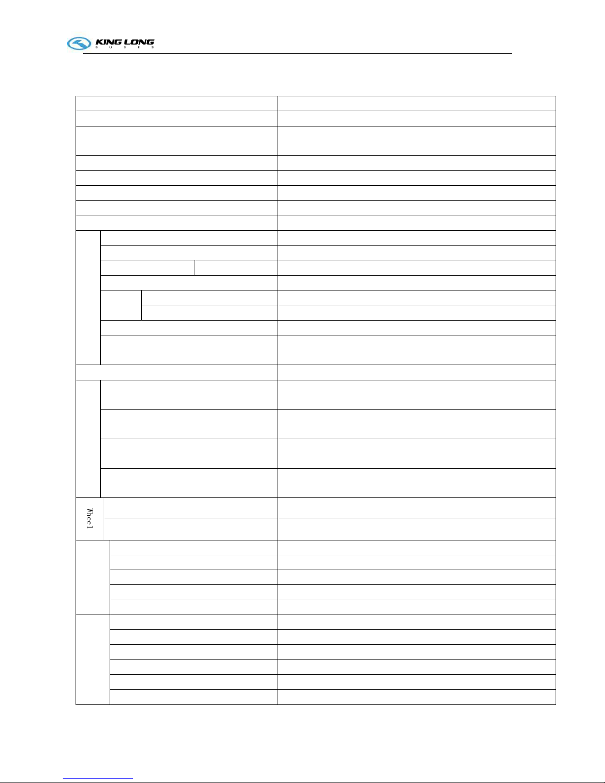
Technical parameters of the complete vehicle
(vehicle No. GA200001)
Product model 6127
Engine model
ISL8.9E5 400
Engine type In-line six-cylinder water-cooling electrically controlled common rail
direct-injection diesel engine
Cylinder diameter ×stroke (mm)
114×145
Displacement (ml)
8900
Compression ratio
16.6:1
Rated capacity / rotation speed (kw/rpm)
294/2100
Max. torque / rotation speed (N·m/rpm)
1700/1300
Dimensions
Overall length (mm)
12000
Overall width (mm) 2490
Overall height(mm) Air spring
3800
Wheelbase (mm) 6350
Wheel
track
front (mm) 2020
rear (mm) 1860
Minimum lift-off clearance(mm) 240
Approach angle/ departure angle (°) 10/9
Front overhang / rear overhang (mm) 2380/3270
Rated passenger (driver included) (person)
49+1+1
Mass parameter
Technically permissible maximum laden mass
(kg)
19000
Technically permissible maximum mass of
combination(kg)
--
Technically permissible maximum laden mass for
front axle (kg)
7500
Technically permissible maximum laden mass for
rear axle (kg)
13000
W
h
e
e
l
Tire size 295/80R22.5
Tire inflation(MPa) 900
Performance
parameter
Max. speed (km/h) 100
Fuel consumption (L) --
Maximum gradeability (%) ≥20
Min. turning diameter (m) ≤24
Parking slope (20%)
Parking for 5 minutes
Capacity data
Fuel tank(L) 300
Engine oil(L) 27.6
Transmission lubricant(L) 20(service oil change),30(dry oil fill)
Main reducing gear lubricant(L) 16
Power steering hydraulic oil(L) 8
clutch lubricant(L) 0

Technical parameter and complete vehicle description
- 8 -
Introduction to specification data plate
Bus data plate
The bus data plate may be affixed to either the upside of the front passenger door frame or to the side of the
front passenger door step (the position may vary with vehicle model). There are many parameters on the
plate, such as vehicle model, gross mass, vehicle serial number, vehicle capacity, VIN (short for vehicle
identification number), chassis serial number, engine serial number, engine model, rated power, production
data and etc..
Chassis data plate
The chassis data plate is on right (or left) lateral surface of the front wheel position of the main sill with
vehicle identification number (VIN) on the frame.
Engine data plate
The engine data plate is on top surface or salient top
position of the engine, whose position may be various
according to different engine manufacturing plant.
The engine number is stamped on the left or right
block of the engine, whose position may be various
according to different engine manufacturing plant.

Technical parameter and complete vehicle description
- 9 -
Product quality assurance
We insist that the end user must make breaking-in maintenance of the rolling-out new vehicles in their
initial driving mileage of 5000 km. The end user should make proper operation and maintenance strictly
according to relevant regulations in the instruction book. Please refer to “workshop manual” for product
quality assurance and strictly abide by the related specification.
Technical document
The instruction book is used combined to the following specification:
Engine operation instruction or service manual
Note: the instruction book should be modified according to specific configuration of vehicle.

Technical parameter and complete vehicle description
- 10 -
Body Structure
1. Structural style
Semi-integral body structure
2. Structure
The bodywork structure adopts closed girder construction of six major assembly parts, which are
combined welded by rectangle steel pipes with advantages of strong structural stiffness, torsion
resistance and bending resistance as well as relatively simple craftwork. Whole vehicle skeleton has
been fully electro-coating operated and anticorrosion treated to ensure steady adhesion of coating and
strong capacity of antirust and corrosion-proof.
3. Interior trim
The interior adopts flexible design and the floor adopts steel plate/wood block composite construction,
and covered with anti-slip and antifriction leather with favorable sound insulation value.
4. Windows
The front windshield is the hyperboloid triplex glass fixed by the gluing; the rear windshield is fixed by
harden glass; the side windows are sealing style , which are all made of hardened glass. The driver’s
window is fixed with sliding window.
5. Baggage compartment
The baggage compartment adopts transverse run-through design, and they are all made of aluminum.
6. Seat
Driver’s seat: Q15-2 adjustable seat with high backrest and three-point belt
Passenger seats: 2+2 layout, KE-1 seats with armrest, foot pedal and transverse movement function ,
49+1+1, all seats are mounted by 3 points seat belt.
7. Interior accessory device
The vehicle is equipped with electronic clock, electric single pieces front windshield sunshade, driver
side sunshade, electric driver window, safety hammer, double emergency escaping windows, curtain
and luxury bilateral C type luggage rack , icebox, middle passenger door, toilet, combination reading
lamp, electric mirrors, DVD player, front and middle flip LCD TV ,reversal monitor , .etc.
8. Air-conditioning system
Cooling /heating A/C system: KING LONG top mounted dependent air-conditioning system,
WEBASTO heating system.
Defroster: cooling /heating defrosting device.
9. Door
The door adopts the full aluminum remote control out-swing single-wing pneumatic passenger doors.
The out-swing door adopts the advanced electrically aerodynamic theory design, with the motion of
opening and closing placidly、agilely、 safely , further, keeping credible locking and anti-clamp
function.
A. Basic function
a. There are two electrically switches, the interior one is trigger touch-tone, which located on the
dashboard of the front right side of the driver, the outside one is a remote control switch. , both switches
can control the door.
b. When the circuit is in OFF position , the emergency switch can be used in the interior and exterior,
the emergency switch of the door is located inwardly upon the entrance of the door and outwardly under
of the door steps , Please rotate the switch and throw open the door in emergency.
c. Commonly the door is closed, when touch off any electrically switch, the door would move placidly
at a certain velocity, along with it, the step-lamp lights .when touch off the switch again , the door
would return placidly at a certain velocity, after the door returned , the step-lamp goes out.
Technical parameter and complete vehicle description
- 11 -
B. Hint:
a. The door remote control acts only when the parking brake is on the parking gear.
b. The door could only be opened when the external mechanical lock isn't locked up.
c. In order to avoid impact, make sure that the door is completed closed or opened, before you make the
next door switch operation.
Note: Deployment on the vehicle may be different with the above description because of different
deploying requirement of the clients.
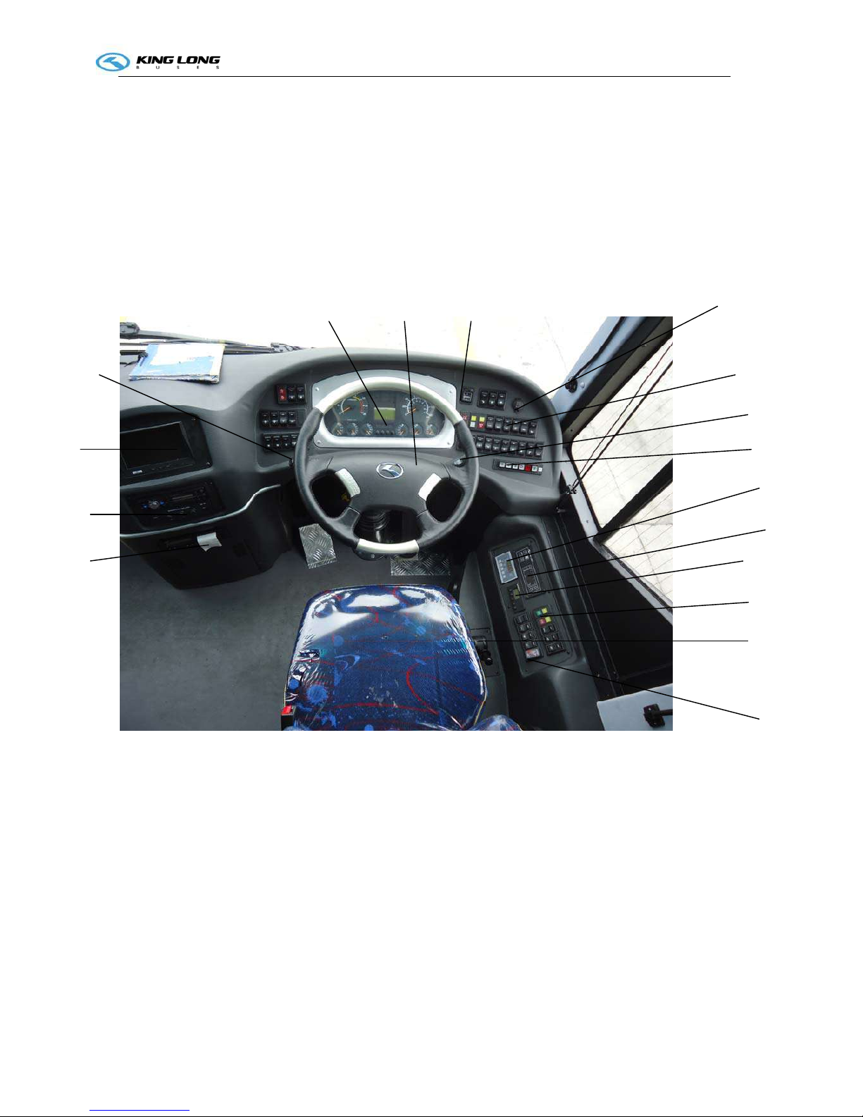
Schematic illustration of the driver zone
1 Fire extinguisher pushbutton
2 Parking brake handle
3 Rocker switch
4 WEBASTO heater panel
5 A/C operation panel
6 Radiator panel
7 Gearbox operation panel
8 Wiper operation handle
9 Rocker switch
10 Power charging socket
11 Mirrors pushbutton
12 Steering wheel
13 Combination instrument
14 Light control handle
15 Back guide monitor
16 MP3 player
17 Travelling data recorder
1
2
4
10
6
5
14
15
3
11 12 13
789
16
17
Operation Instruction
CI-1
Instruction of instrument (VITI EDITION)
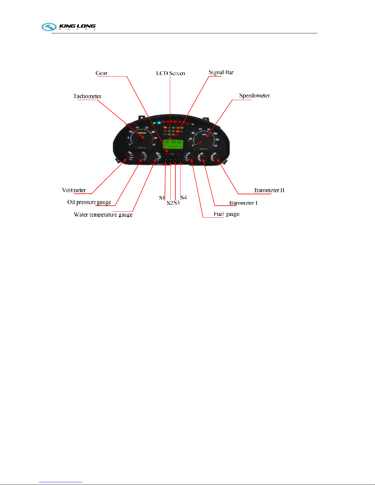
Figure-1 The Outline of ZB271M
The appearance of the ZB271M dashboard as shown in Figure-1 , it mainly contains eight indicator
type measuring instruments, 29 icons which were lighted by the light-emitting diodes, one LCD screen and
four buttons, dashboard pin definition go to Appendix A
2.1 Display Part.
1.Gear P—Brake gear, R—Reverse gear,N—Neutral gear,D—Drive gear,S—Safety belt.
2.Signal Bar. Go to Appendix B.
3.Speedometer .Display speed of bus. Units :Km/h.
4.BarometerI and Barometer II. Display air pressure of bus. Units: 0.1MPa .
5.Fuel gauge. Display amount of fuel. Units: Percentage.
6.Water temperature gauge .Display engine temperature of bus. Units: ℃.
7.Oil pressure gauge. Display oil pressure gauge of bus. Units : 0.1MPa.
8.Voltmeter .Display Voltage of car. Unit: V.
9.Tachometer .Display rotate speed of bus. Units: r/min.
10.LCD Screen. Display interface information, engine information and so on. Go to Appendix C.
2.2 Button part
Operation Instruction
CI-1
ZB271M dashboard has four buttons,S1、S2、S3、S4.
S1—Set Button. S2—Up Button. S3—Down Button. S4—Return Button.
S1 could set some information of dashboard, for example ,times, blacklight, VehPPK and so on.
S2 and S3 could flip the screen up or down.
S4 Return main interface.
Remarks: Do not press S1 when flip the screen up or down.
3 Instructions
3.1 LCD Display
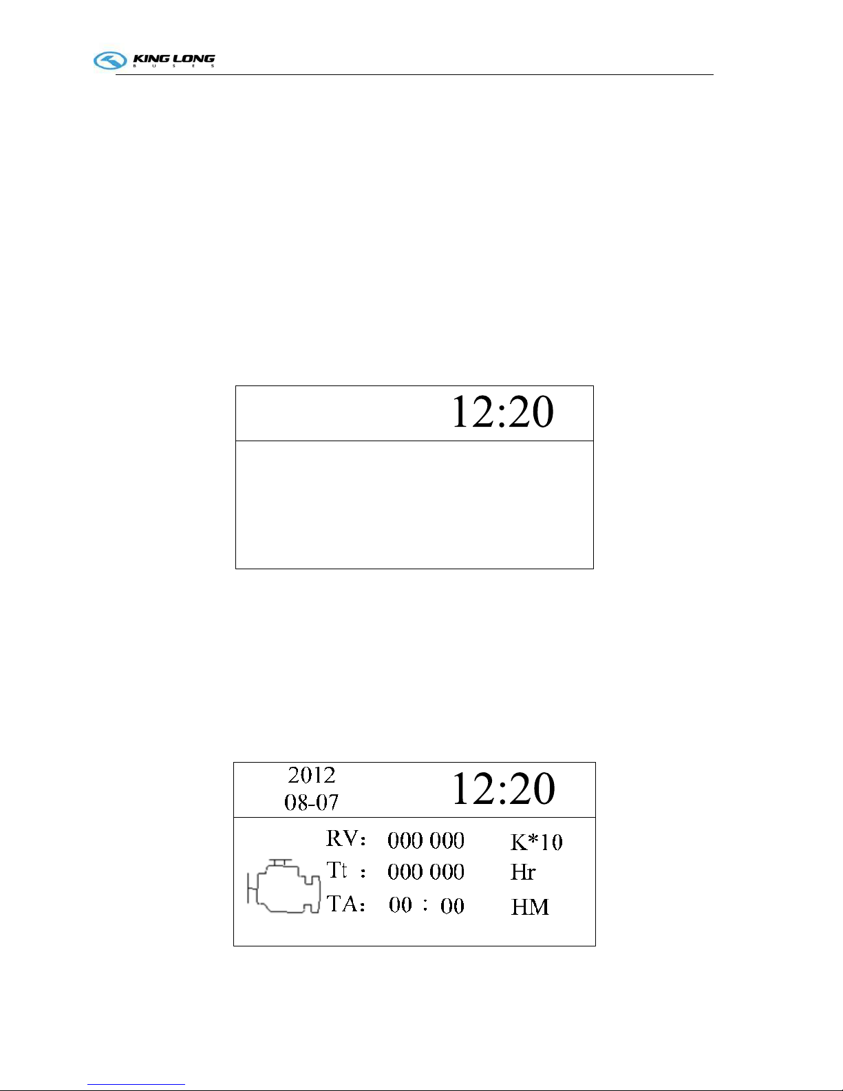
3.1.1 After power on as shown in Figure-2: Total Mileage, Trip Mileage A and Trip Mileage B
2012
08-07
Total:
TripA:
TripB:
000.0
000 000 Km
Km
000.0
Km
Figure-2 Main interface
3.1.2The second interface display engine information,as shown in Figure -3.
Accumulated rotates and Engine running time.
Figure-3 Engine information
3.1.3 The third and the fourth interface display information of Fuel and Mileage as shown in Figure -4 and

Operation Instruction
CI-1
Figure -5.
Figure-4 Fuel and Mileage information
2012
08-07
0000000000 .0 L
0000000000 .0 L
Figure-5 Fuel and Mileage information
3.1.4 The fifth interface display CNG and Catalyst. as shown in Figure-6
2012
08-07
C N G
CATALYST
0000
Bar
000
%
Figure-6 CNG and CATALYST
3.1.5 The sixth display inside temperature,outside temperature and engine compartment temperature. as
shown in Figure-7
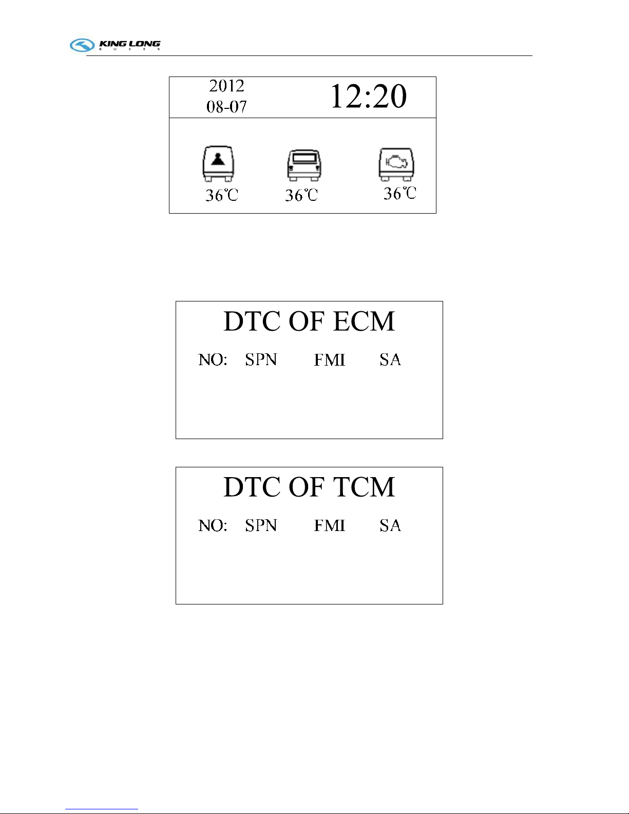
Operation Instruction
CI-1
Figure-7 Car and Engine compartment temperature
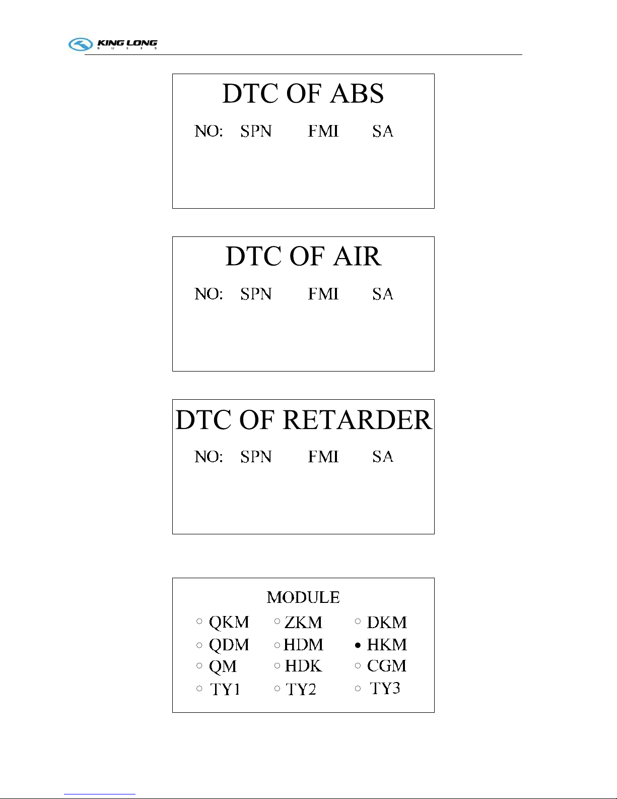
3.1.6 The seventh、eighth、ninth、tenth and eleventh interface display ECM、TCM、ABS、AIR、Retarded
information. as shown in Figure-8、9、10、11、12.
Figure-8 ECM Code
Figure-9 TCM Code
Operation Instruction
CI-1
Figure-10 ABS Code
Figure-11 AIR Code
Figure-12 Retarded Code
3.1.7 The thirteenth interface display online module. as shown in Figure-13.
Operation Instruction
CI-1
Figure-13 Online Module
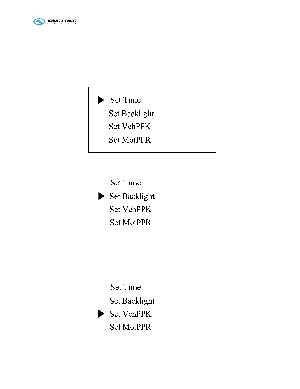
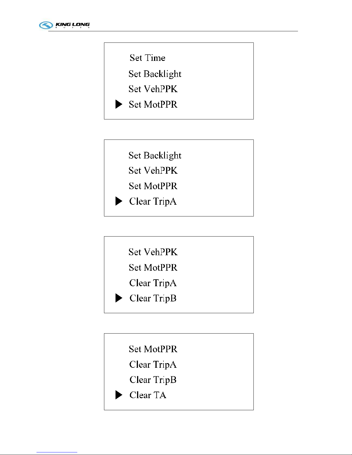
3.2 Dashboard Set
3.2.1 First,Press S1 go to set interface, Second, Press S2 and S3 flip the interface up or down.
Could Set Time、Set Backlight、Set VehPPK、Set MotPPR、Clear Trip A、Clear Trip B、ClearTA、
Clear Oneway OC. as shown in Figure-14、15、16、17、18、19、20、21
Figure-14 Set Time
Figure-15 Set Backlight
Figure-16 Set VehPPK
Operation Instruction
CI-1
Figure-17 Set MotPPR
Figure-18 Clear Trip A
Figure-19 Clear Trip B
Operation Instruction
CI-1
Figure-20 ClearTA
Figure-21 Clear Oneway OC
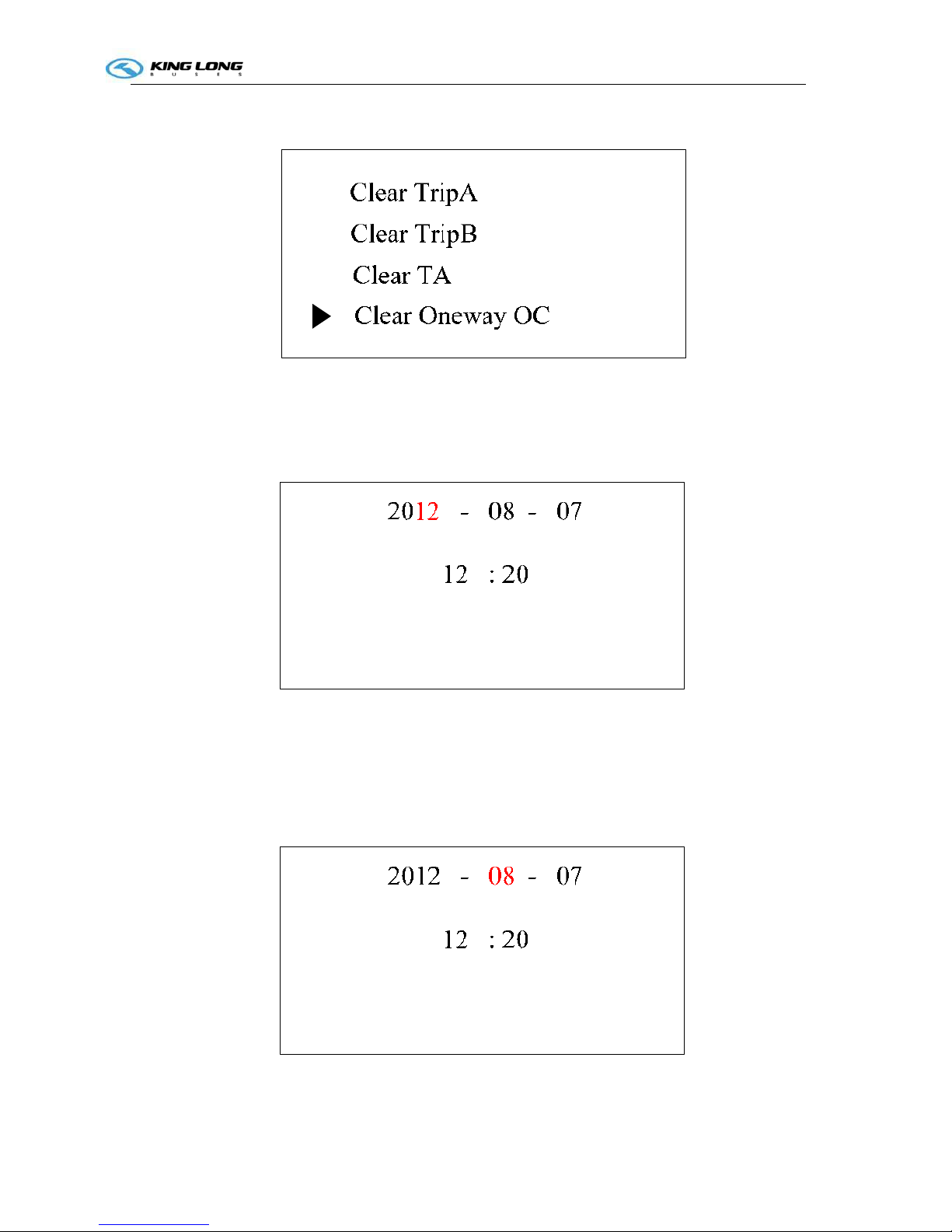
3.2.2 Set Time .First press S1 go to set interface, Second press S2 or S3 choose Set Time position as
shown in Figure-14, Third press S1 go to Figure-22.
Figure-22 Set Year
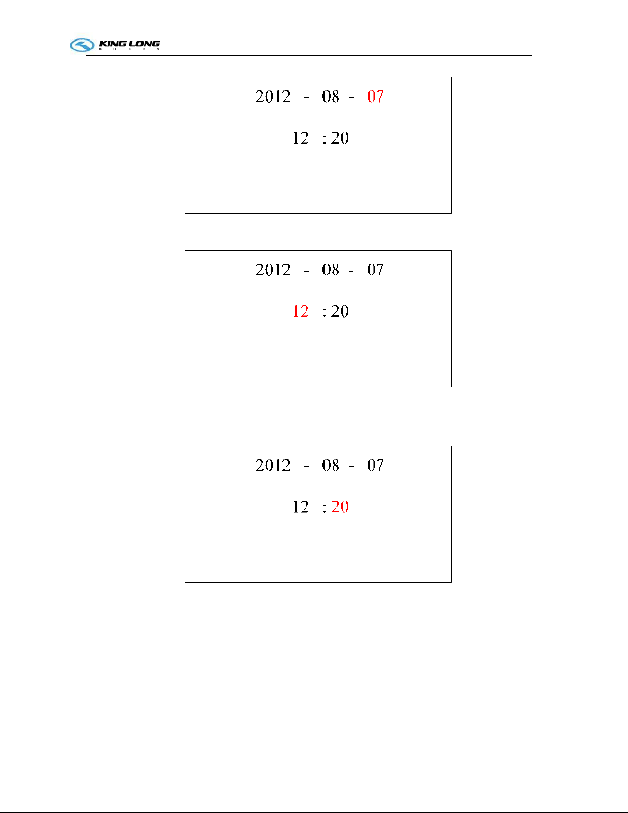
Finally press S2 and S3 could increase or decrease years. After set year, could press S1 choose Month、
Day、Hour、Minute as shown in Figure-23、24、25、26.And press S2 and S3 could set Month、Day、
Hour、Minute. After Set press S4 two times return main interface.
Figure-23 Set Month
Operation Instruction
CI-1
Figure-24 Set Day
Figure-25 Set Hour
Figure-26 Set Minute
3.2.3 Set Backlight. First press S1 go to set interface, Second press S2 or S3 choose Set Backlight
position as shown in Figure-15, Third press S1 go to Figure-27.
Operation Instruction
CI-1
Set Backlight
Backlight 80
Figure-27 Set Backlight
Finally press S2 and S3 could increase or decrease backlight. After set backlight, press S4 two times
return main interface.
3.2.4 Set VehPPK. First press S1 go to set interface, Second press S2 or S3 choose Set VehPPK position
as shown in Figure-16, Third press S1 go to Figure-28.
Set VehPPK
VehPPK 0624
Figure-28 Set VehPPK
Finally press S2 and S3 could increase or decrease VehPPK. After set VehPPK, press S4 two times
return main interface.
3.2.5 Set MotPPR. First press S1 go to set interface, Second press S2 or S3 choose Set MotPPR
position as shown in Figure-17, Third press S1 go to Figure-29.
Set MotPPR
MotPPR 0173
Operation Instruction
CI-1
Figure-29 Set MotPPR
Finally press S2 and S3 could increase or decrease MotPPR. After set MotPPR, press S4 two times
return main interface.
3.2.6 Clear Trip A. First press S1 go to set interface, Second press S2 or S3 choose Clear Trip A
position as shown in Figure-18. Third press S1 clear Trip A and auto return main interface.
3.2.7 Clear Trip B. First press S1 go to set interface, Second press S2 or S3 choose Clear Trip B
position as shown in Figure-19. Third press S1 clear Trip B and auto return main interface.
3.2.8 Clear TA. First press S1 go to set interface, Second press S2 or S3 choose Clear TA position as
shown in Figure-20. Third press S1 clear TA and auto return main interface.
3.2.9 Clear One way OC. First press S1 go to set interface, Second press S2 or S3 choose Clear One
way OC position as shown in Figure-21. Third press S1 clear One way OC and auto return main interface.
Appendix A ZB271M Dashboard Pin Definition
Table A Pin Definition
Pin Name Color Remark
1 VPP Red
2 GND Black
3 WAKE_UP1 Red Connected to WAKE_UP2
inside
4 CANH1 Yellow Connected to CANH2
inside
5 CANH2 Yellow
6 CANL1 Green Connected to CANL2
inside
7 CANL2 Green
8 Empty
9 Empty
10 Empty
11 WAKE_UP2 Red
12 Empty
13 Empty
Operation Instruction
CI-1
14 Empty
15 Empty
16 Empty
17 Empty
18 Empty
19 Empty
20 Empty
21 Empty
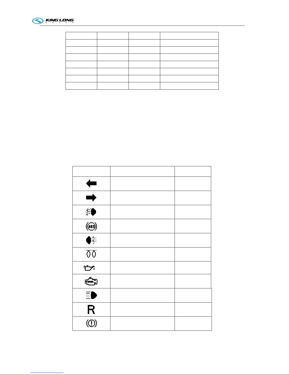
Appendix B ZB271M Signal Bar instructions
Icon Name Color
Left turn light Green
Right turn light Green
Front fog light Green
ABS Yellow
Rear fog light Yellow
Pre-heater Yellow
Alarm of oil pressure Red
Engine fault Yellow
High beam Blue
Reverse Red
Alarm of gas pressure Red
Operation Instruction
CI-1
Clearance Lamp Green
Avoid side slide Red
Charge Red
Parking light Red
Low beam Green
Alarm of water temperature Red
Alarm of Fuel Low Red
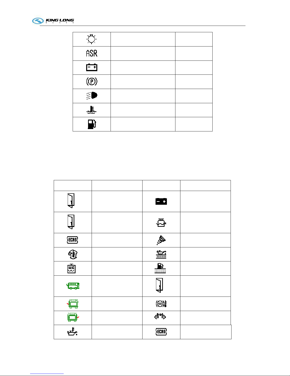
Appendix C ZB271M LCD Alarm instructions
Icon Icon Name Icon Icon Name
Front Door
Low Power
Middle Door
Alarm of water level
ECAS Fault
Concentrate lubrication
Engine cabin
temperature too high
Alarm of oil filter
Lack water alarm of
W. C
Alarm of oil filter
Rear cabin door
Rear Door
Left cabin door
Alarm of Retarded
temperature
Right cabin door
Fault of turn light
Alarm of Oil
Temperature
Alarm of ECAS
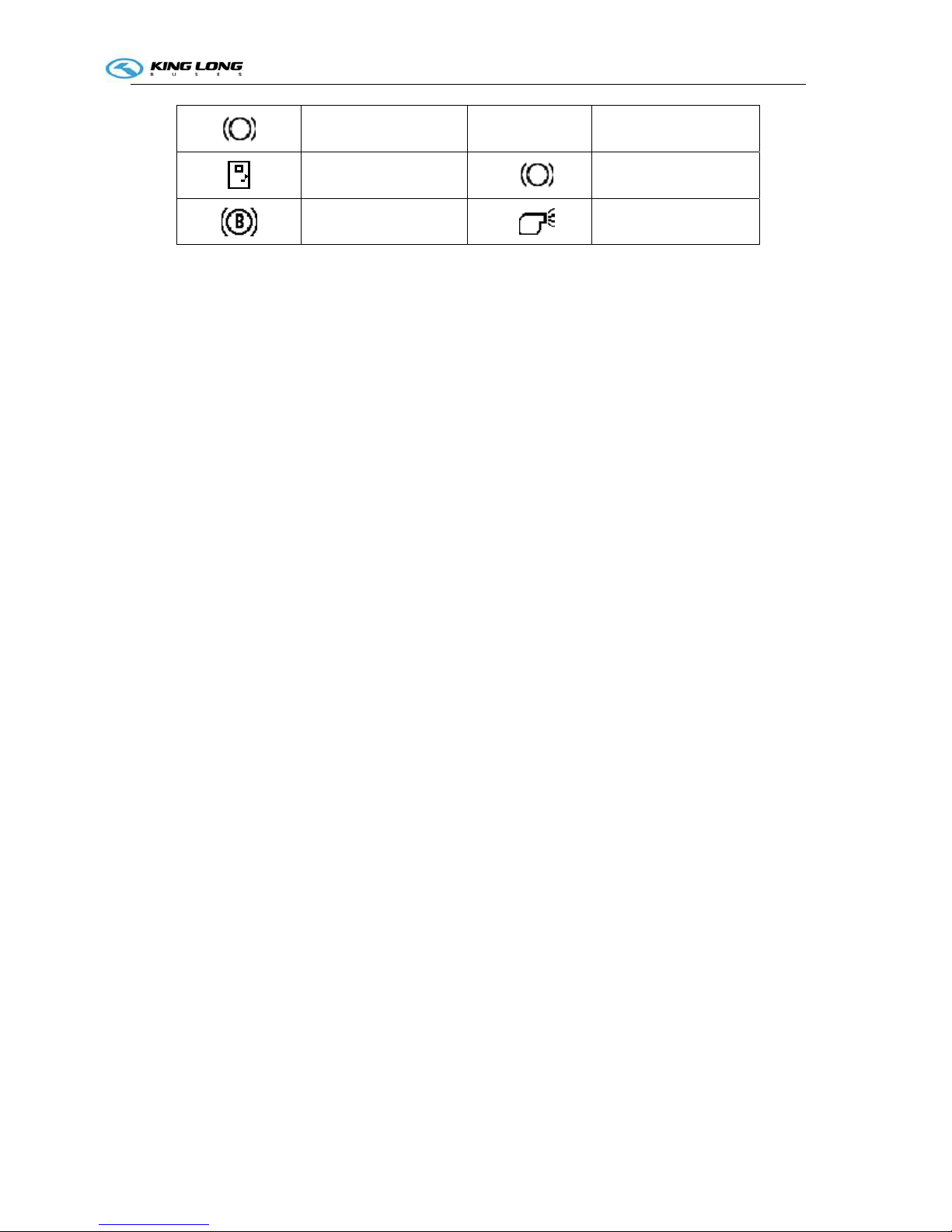
Operation Instruction
CI-1
Brake Light Fault CRUISE Cruise
Safety Door
Brake Light
Break Wear
Antifreeze controller
Operation Instruction
CI-1
Illustration of switch and indicator
Number of switches , indicators and their own positions may vary with the vehicle model and configuration
state, please refer to the flowing sheet :
Switch
Name Color Function Notes
Retarder foot control
function release switch
White
Pressed on up: foot control function is
turned ON
Pressed on bottom: foot control function is
turned OFF
Daylight lamp
White
Pressed on top: interior lighting OFF
Pressed on bottom: interior lighting ON
Hazard alarm lamp
Red
Pressed on bottom: all turning indication
lamps will turn on
Luggage compartment
lamp
White
Pressed on top: the luggage cabin lamp OFF
Pressed on bottom: the luggage cabin lamp
ON
Ventilator
White
Pressed on top: the ventilator is turned off
Pressed on bottom: the ventilator is turned
on
Front fog lamp
White
Pressed on top: the front fog lamp OFF
Pressed on bottom: the front fog lamp ON
Rear fog lamp
White
Pressed on top: the rear fog lamp OFF
Pressed on bottom: the rear fog lamp ON
Reading lamp
White
Pressed on top: the reading lamp OFF
Pressed on bottom: the reading lamp ON
Front windshield
defrosting switch
White
Pressed on top: turn off defrosting function
Pressed on bottom: turn on defrosting
function
Operation Instruction
CI-1
Vehicle body
raise/lower switch
White
Pressed on top: the vehicle body raise
Pressed on bottom: the vehicle body descend
only use this
button when
vehicle is
stopping
Kneeling/Restoration
switch
White
Pressed on top: the vehicle will return to
the normal height
Pressed on bottom: the vehicle will kneel
Pressed the
switch down
only when the
passengers get
on or get off the
vehicle
ECAS 2th height switch
White
Pressed on top: the airbags will return to
the standard height(I height)
Pressed on bottom: the airbags will return to
the second height (II height)
The switch
should be
pressed down
only at bad road
condition.
Heating valve (water
heating circulation
solenoid valve) switch
White
Pressed on top: the valve is switched off
Pressed on bottom: the valve is switched on
Heating radiator switch
White
Pressed on top: the radiator is switched off
Pressed on bottom: the radiator is switched
on
Fresh air ventilating
switch
White
Pressed on top: the ventilation function is
switched off
Pressed on bottom: the ventilation function
is switched on
Operation Instruction
SI-2
Switch Name Color Function Notes
Horn
White
Pressed on top: the electric horn is turned on
Pressed on bottom: the air horn is turned on
Emergency
power switch
Red
Pressed on top: turn off the vehicle
power
Pressed on bottom: turn on the vehicle
power
1) While only turn on the
switch, could supply
power only for 2
minutes;
2) Meanwhile, if also
rotate the ignition key
to ACC or ON shift,
thus could supply
power for long.
Driver
window
defrosting
switch
White
Pressed on top: the defrosting is turned off
Pressed on bottom: the defrosting is turned
on
Driver
window
raise/lower
switch
White
Pressed on top: the window will raise
Pressed on bottom: the window will descend
Front
windshield
sunshade
switch
White
Pressed on top: the sunshade will be raised
Pressed on bottom: the sunshade will be
descended down
Disinfection
function
switch
White
Pressed on top: switch off the disinfection
function
Pressed on bottom: switch on the
disinfection function
Rearview
mirror
defrosting
switch
White
Pressed on top: turn off defrosting function;
Pressed on bottom: turn on the defrosting
function.
Front
passenger
door switch
White
Pressed on top: close the door
Pressed on bottom: open the door
Operation Instruction
SI-2
Rear
passenger
door switch
White
Pressed on top: close the door
Pressed on bottom: open the door
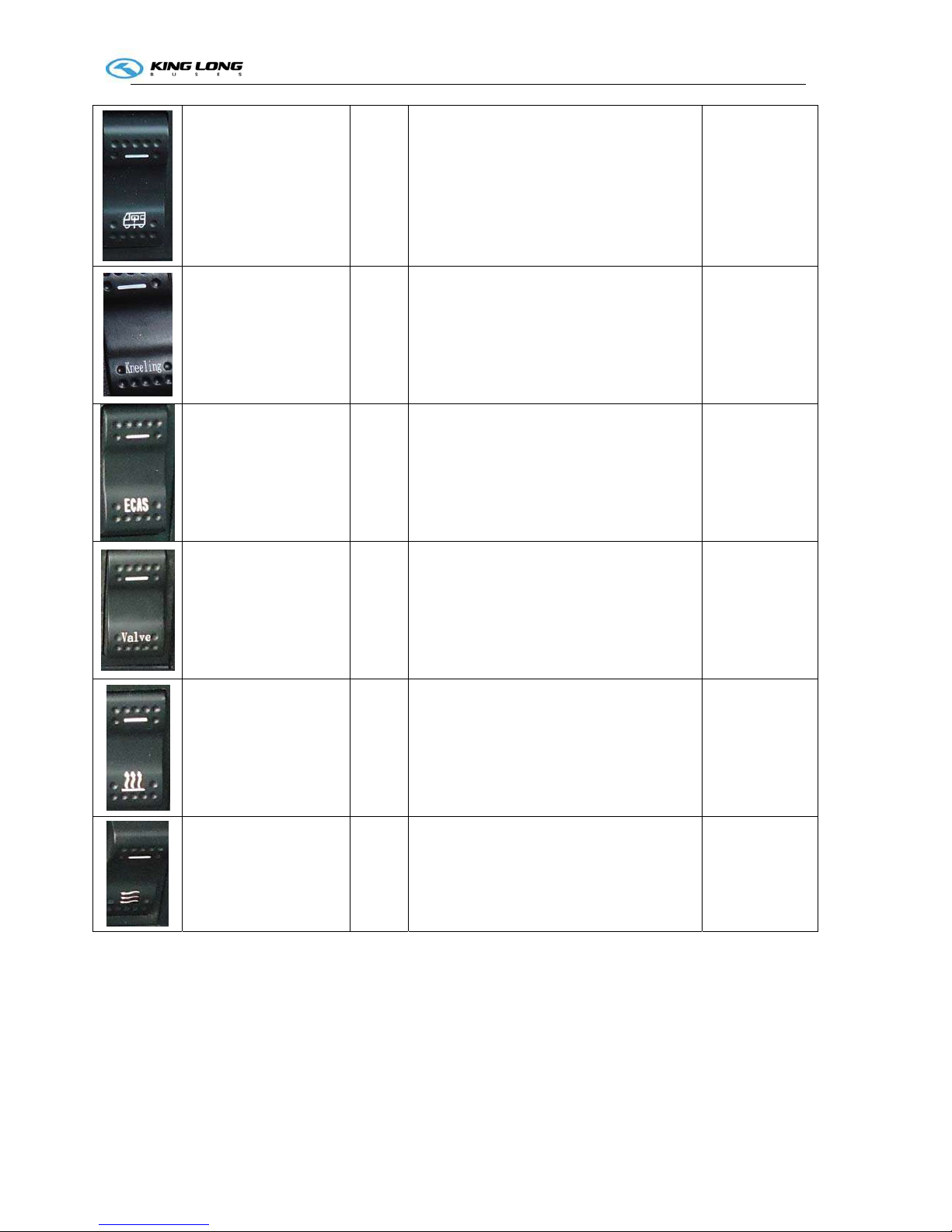
Flip TV
switch
White
Pressed on top: turned off the power, folded
the TV
Pressed on bottom: turned on the power,
unfolded the TV
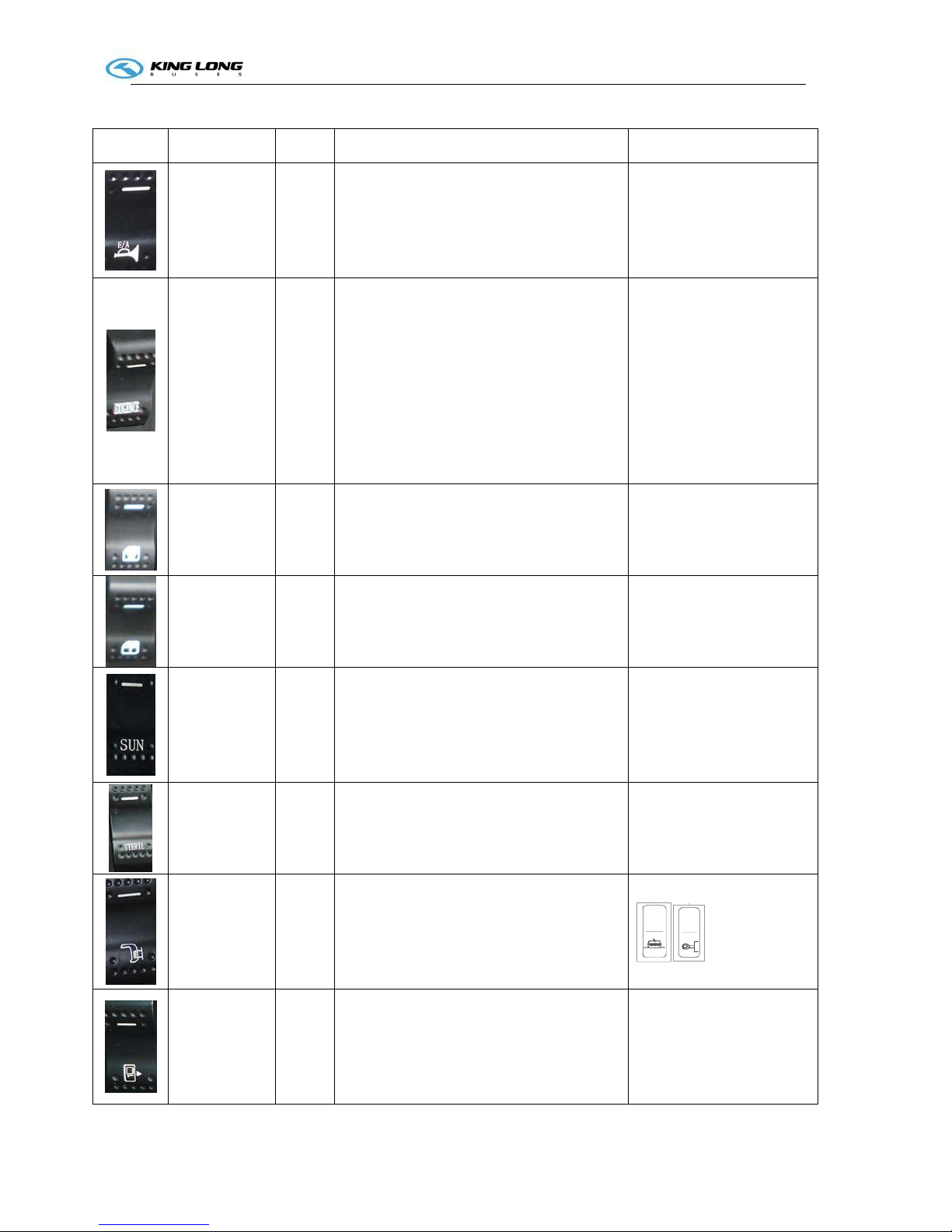
Engine cabin
fire
extinguisher
switch
Red
Pressed down : extinguisher will be activated
The powder will be burst
out and coated on engine
cylinder block so as to
block up flame and
combustion. Don't test to
press this button down at
normal condition
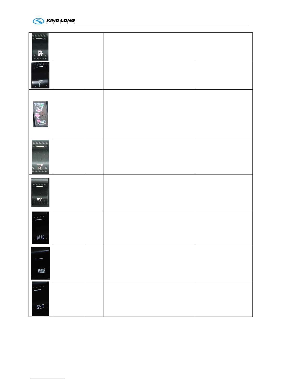
Reversal
monitor
switch
White
Pressed on top: turned off the reversal
monitor power
Pressed on bottom: turned on the reversal
monitor power
Toil et p o w e r
switch
White
Pressed on top: turned off the toilet power
Pressed on bottom: turned on the toilet
power
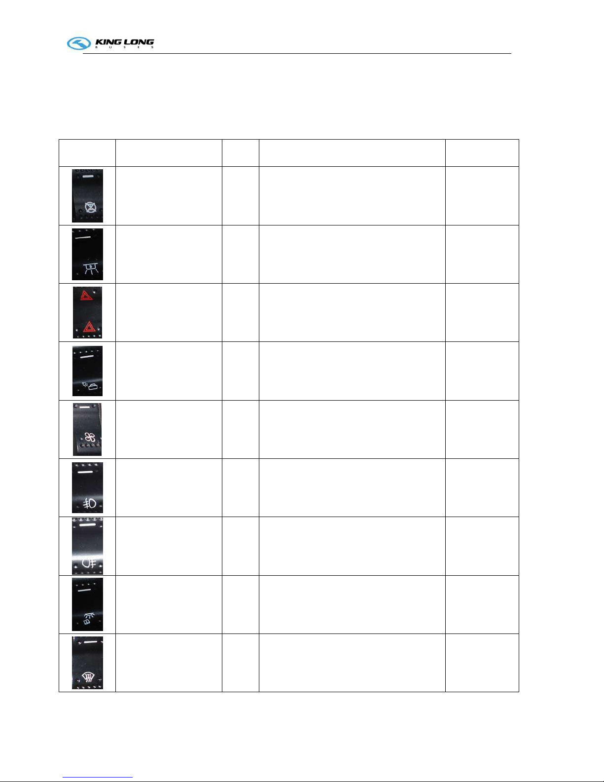
Engine
Diagnose
function
switch
White
Pressed on top: turned off the engine
diagnose function
Pressed on bottom: turned on the engine
diagnose function
Engine cruise
function
switch
White
Pressed on top: turned off the engine cruise
function
Pressed on bottom: turned on the engine
cruise function
we advise clients not to use
this switch
Cruise set
switch
White
Pressed on top: turned off the engine cruise
set
Pressed on bottom: turned on the engine
cruise set
we advise clients not to use
this switch
Operation Instruction
SI-3
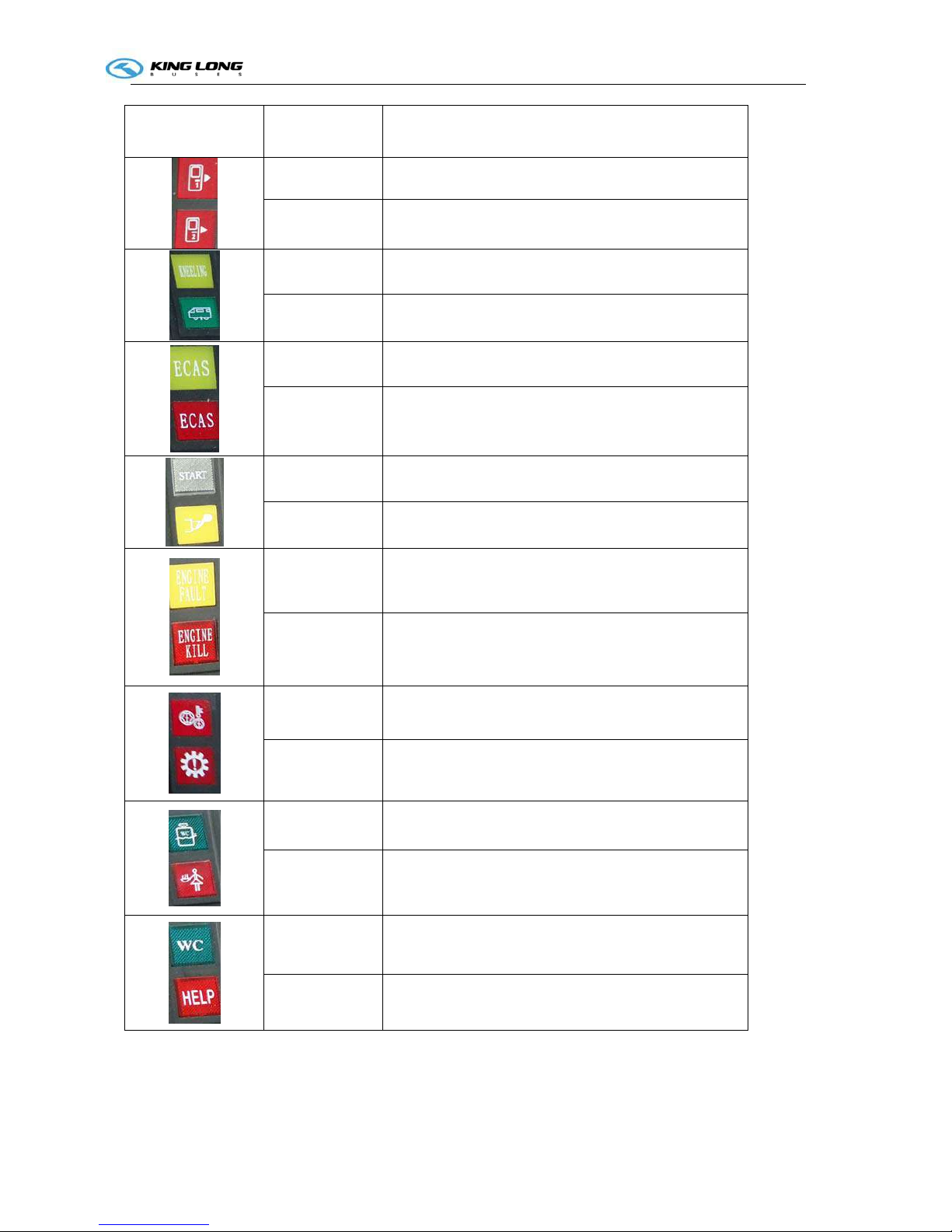
Indicator lamp
Color
Function
Red Front passenger door opening alarm
Red Rear passenger door opening alarm
Yellow Kneeling working indication
Green The 2th height state indication
Yellow ECAS alarm indication
Red ECAS fault indication
White Engine start indication
Yellow Exceeding emission standard indication
Yellow Engine slight fault alarm
White Engine serious fault, engine stopped
Red Transmission oil temperature too high alarm
Red Gearbox fault alarm
Green Toilet water level two low indication
Red Toilet fault alarm
Green Toilet occupancy indication
Red Request emergency help alarm
 Loading...