

KING Jack OA8501, OA8500 Owner's Manual
Low Prole Digital HDTV Over-the-Air Antenna
with built-in KING SureLock™ Digital TV Signal Meter
Owner’s Manual
Roof Thickness: 1” to 4-1/2”
Roof Thickness: 4-1/2” to 8”
(when installed with KING extension #21850)
OA8500 • White
OPERATION and AIMING THE ANTENNA .........................................................1
CONTENTS and EXTENSION INSTALLATION ..................................................2
EXTERIOR BASE MOUNT INSTALLATION .......................................................3
INTERIOR ENCLOSURE INSTALLATION ..........................................................4
POWER INSERTER INSTALLATION ..................................................................5
LIMITED WARRANTY .........................................................................................6
NOTE: Please read thru the installation instructions before beginning.
See page 2 for items supplied by the installer.
See page 5 for information on the MB8200 Mounting Plate
SPECIFICATIONS
Dimensions: 8.7” H x 16” W x 12.5” L
Weight: 2.62 lbs.
Power Requirement: 12 VDC / 100 mA
(supplied by KING Wall Mount Power Injector)
OA8501 • Black
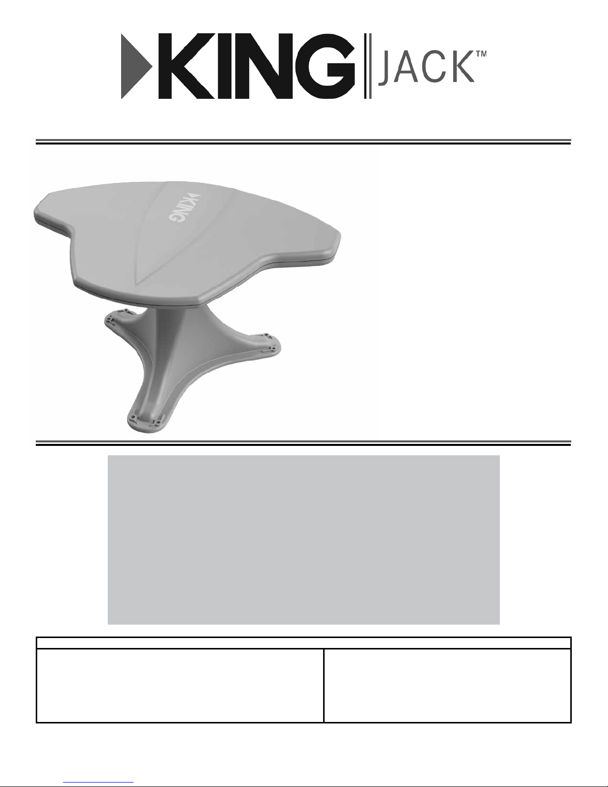
CONTENTS
Frequency Bands: VHF (54-216 MHz)
UHF (470-698 MHz)
FM (87.9-107.9 MHz)
Signal Meter Frequency Response: 54-698 MHz (Ch 2-51)
Enclosure/Mount: ASA-Automotive grade
Thank you for choosing a KING Antenna!

OPERATION
AIMING THE ANTENNA
1. Turn on TV and power injector (see above).
2. Turn on KING SureLock Signal Meter with switch on side of enclosure.
3. Press button and turn knob to rotate antenna in
one direction until it hits the stop.
4. Rotate attenuator dial fully clockwise.
5. Slowly rotate antenna a full 360 degrees.
Antenna will hit stop again.
As you rotate it, note where the maximum
number of LEDs illuminate on signal meter.
If the same number of LEDs stay lit through the whole rotation,
turn the attenuator down slightly and rotate the antenna again.
Rotate the antenna back to where the most
LEDs illuminated and center it in that area.
Arrow on knob indicates which direction
antenna is pointing.
LEDs will illuminate from left
(next to power) to right.
All LEDs may not illuminate depending
on signal strength.
6. Rotate attenuator dial counter clockwise until last illuminated LED ickers.
7. Rotate antenna back and forth slightly to illuminate ickering LED.
8. Repeat steps 6 and 7 to pinpoint signal reception.
9. Follow instructions in TV or converter box owner’s manual to scan for available channels. Watch TV!
Page 1
CONTENTS
IMPORTANT!
For roofs 4-1/2” to 8”
thick, install
KING extension #21850.
IMPORTANT!
You must install
the included
wall mount
power inserter
to operate the
KING Jack
antenna
(see page 5).
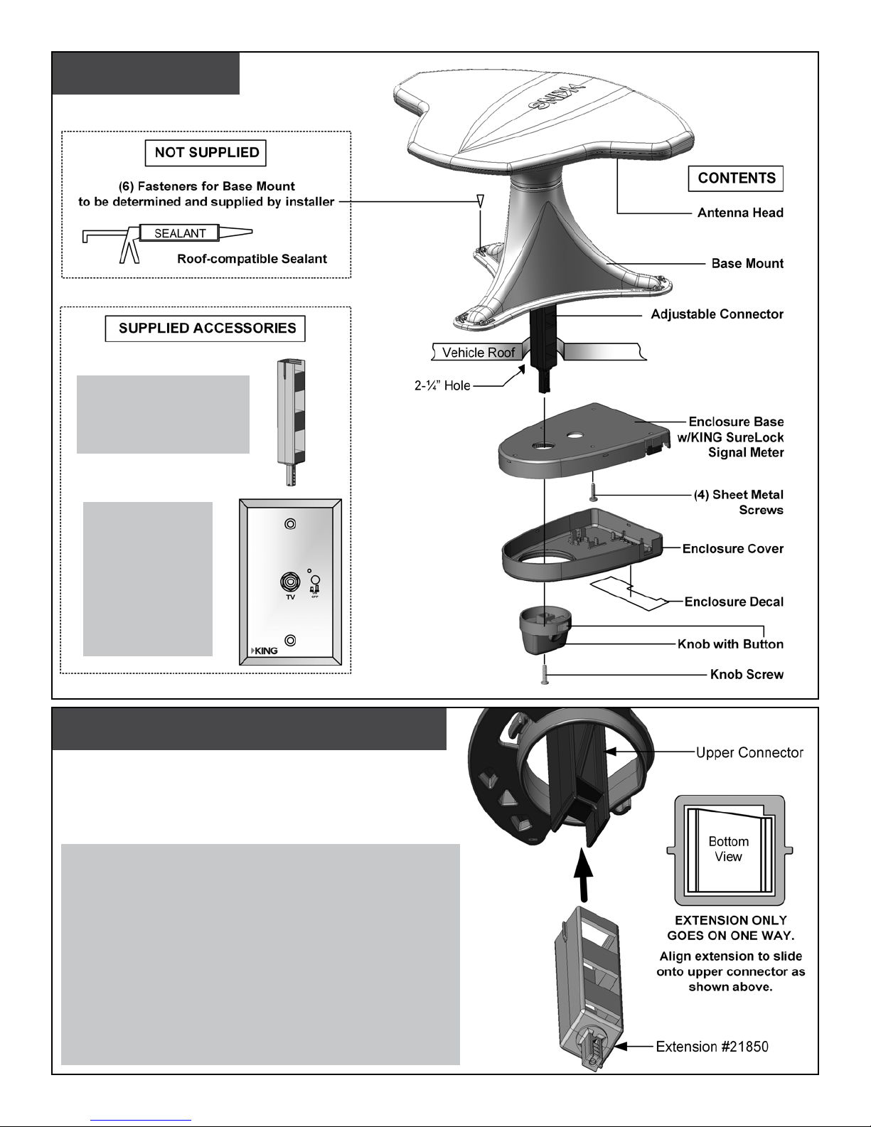
EXTENSION INSTALLATION
ROOFS 4 1/2” to 8” THICK ONLY!
Roofs thinner than 4 1/2” go to next page.
If your roof is 4-1/2” to 8” thick
you will need to install KING extension #21850.
If using the extension, install it now,
BEFORE INSTALLING BASE MOUNT ON ROOF.
• Remove the existing adjustable connector from the upper
connector located in the base mount.
• Extension only ts onto upper connector one way. Line up
as shown at right and engage the extension onto the upper
connector.
• Leave extension sticking out of base mount more than the
thickness of the roof.
Page 2
 Loading...