

KING Jack OA8000, OA8001 Installation Instructions Manual
VHF + UHF Amplifi ed HDTV Antenna
Model OA8000 & OA8001 Installation Instructions
VoltageReception Frequencies
VHF: 47-230 MHz
UHF: 470-860 MHz
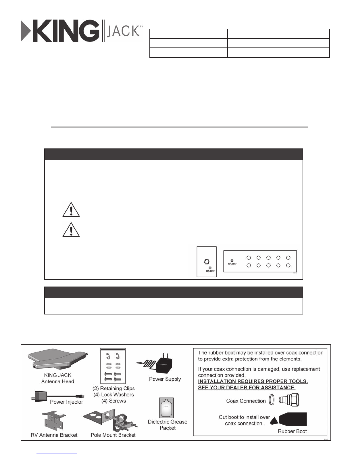
STEP 1: Verify all components and parts are included, using fi gure at bottom of this page.
STEP 2: Install the KING JACK Antenna in one of two ways (Page 2):
• RV Mounting: Mount to a bat wing style retractable arm using the supplied RV Antenna Bracket.
• Pole Mounting: Mount to a stationary pole (on a house for example) using the supplied Pole Mount Bracket.
DO NOT MOUNT TO A POLE ON A VEHICLE.
Input: AC110-120V / AC220-240V
Working: DC12V / 100mA
STEP 3: READ THE FOLLOWING INFORMA
The KING JACK antenna is an amplifi ed antenna that requires +12 volts power.
When using an existing power injector already in the RV
When replacing an existing amplifi ed antenna that has an existing power injector, just replace
the antenna head assembly and verify that you have power to the KING JACK antenna when the
wall switch power injector is “ON.” A red LED light on the bottom of the KING JACK antenna will
illuminate when +12 volts is present and the internal amplifi er is powered. Do not use both the
existing power injector and the power injector supplied with the KING JACK Antenna!
Using two power injectors in the circuit can cause the KING JACK Antenna
power supply to overheat, possibly causing injury or severe damage.
Use either the existing power injector or the KING JACK power injector.
WARNING: DO NOT USE BOTH POWER INJECTORS!
A typical power injector for an
existing RV antenna will be a wall
plate or A/V distribution box with an
ON/OFF type switch.
TION CAREFULLY, THEN MAKE CONNECTIONS ON PAGE 3.
When using the KING JACK antenna with the supplied power injector
Verify that any existing power injector has been disconnected.
STEP 4: Read the OPERATING INSTRUCTIONS on page 4 for antenna pointing instructions.
Page 1
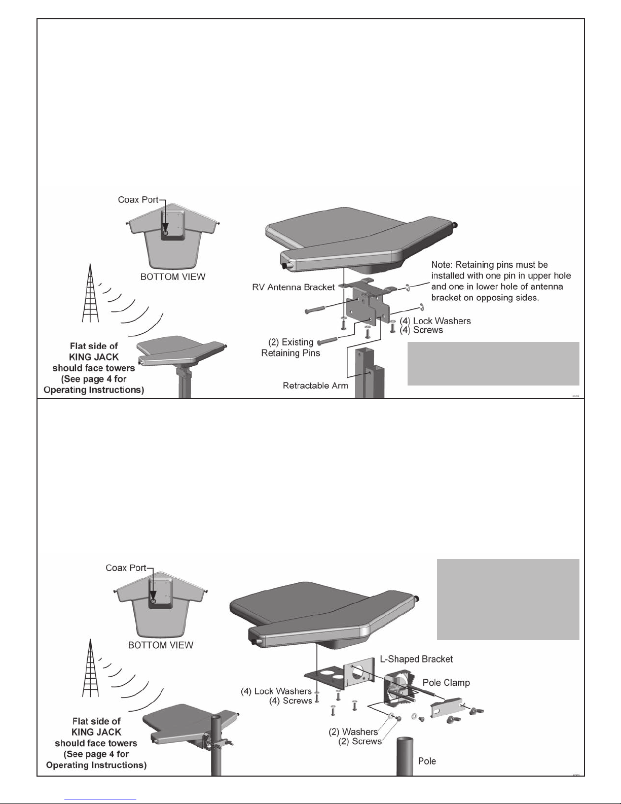
Option 1: BAT WING STYLE REPLACEMENT
1. Turn off antenna power injector at wall switch or A/V switch and raise the existing antenna.
2. Attach the RV antenna bracket to the KING JACK antenna with the 4 supplied sets of lock washers and screws.
3. Unscrew coax cable and remove existing bat wing style antenna (if present) from the retractable arm (keep retaining pins and
clips). Line up holes in RV antenna bracket with holes in retractable arm and re-insert pins thru assembly. Re-install retaining
clips (use new supplied retaining clips if necessary).
4. Fill end of existing coax cable with supplied dielectric grease and screw to antenna (DO NOT OVER TIGHTEN).
Note: If existing coax connector is corroded or damaged, replace with supplied new connector.
If installing new coax cable (sold separately), connect as stated, and then route properly thru retractable arm and into vehicle.
Make appropriate connections in vehicle.
Antenna may be mounted in either
direction in order to clear obstacles such
as AC units or roof vents.
Option 2: POLE MOUNT BRACKET
1. Attach the L-shaped bracket to the KING JACK antenna with the 4 supplied sets of lock washers and screws.
2. Remove 2 existing screws and 2 existing washers from L-shaped bracket. Attach pole clamp to the L-shaped bracket with the
same screws and washers.
3. Place the clamp around an appropriate pole and tighten wing nuts.
4. Fill end of coax cable (sold separately) with supplied dielectric grease and screw to antenna (DO NOT OVER TIGHTEN).
Note: If replacing an existing antenna and the existing coax connector is corroded or damaged, replace with supplied new
connector. Route coax cable and make appropriate connections.
5. Position antenna for maximum signal reception and tighten wing nuts to secure the antenna in this position.
POLE MUST BE STATIONARY -
NOT ON A VEHICLE.
This is a directional antenna
and should be rotated on the
pole to the position that provides
maximum signal reception.
Page 2
 Loading...