

Page 1
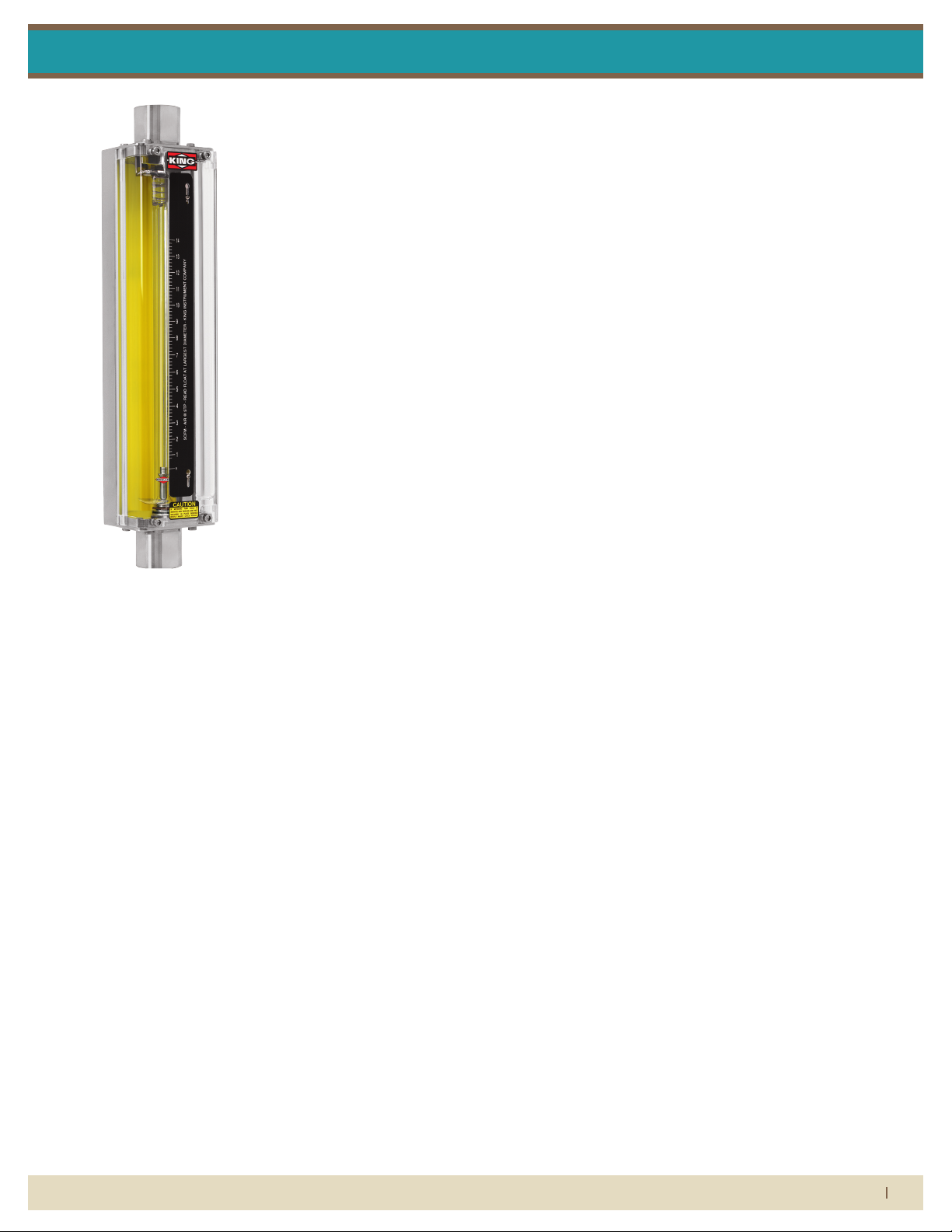
Silver Series
Installation Instructions
Flow Meter liMited warranty
Meters are warranted against defects in materials and workmanship to the original user for a period of
thirteen (13) months from the date of factory shipment, provided the meter is installed, operated and
maintained in accordance with King Instrument Company’s instructions and recommendations.
This warranty does not apply if failure is caused or contributed to by any of the following: improper
handling, improper storage, abuse, unsuitable application of the product, lack of reasonable and
necessary maintenance, use exceeding suggested pressure and temperature maximums, improper
packaging for return, or repairs made or attempted to be made by anyone other than King Instrument
Company, Inc.
KING INSTRUMENT COMPANY, INC. MAKES NO WARRANTY AS TO THE FITNESS OF ITS PRODUCTS FOR
SPECIFIC APPLICATIONS.
This warranty is valid for the original end-user only and does not apply to products that have been
damaged or modied. This warranty is non-transferrable and is limited to replacement or repair. The
liability of King Instrument Company arising out of its supply of the products, or their use, shall not in
any case exceed the cost of correcting defects in the products as set forth above.
THIS WARRANTY IS A LIMITED WARRANTY AND SHALL BE IN LIEU OF ANY OTHER WARRANTIES,
EXPRESSED OR IMPLIED, INCLUDING BUT NOT LIMITED TO ANY IMPLIED WARRANTY OR MERCHANTABILITY OR FITNESS FOR A PARTICULAR PURPOSE. THERE ARE NO OTHER WARRANTIES WHICH EXIST
BEYOND THE DESCRIPTION OR FACE HEREOF.
IN NO EVENT SHALL KING INSTRUMENT COMPANY BE LIABLE FOR LOSS OF PROFITS, INDIRECT, CONSEQUENTIAL OR INCIDENTAL DAMAGES.
Products should be returned, prepaid, to King Instrument Company, Inc. with proof of purchase. Call
factory for Return Merchandise Authorization (RMA) number and return instructions.
this is iMportant inForMation.
read it careFully beFore beginning work.
1) Inspect meter for damage that may have occurred during shipping.
Report any damage to the container to the freight carrier immediately.
2) Make sure your pressure, temperature, uid and other requirements
are compatible with the meter and components (including o-rings).
3) Select a suitable location for installation to prevent excess stress on
the meter which may result from:
a) Misaligned pipe.
b) The weight of related plumbing.
c) “Water Hammer” which is most likely to occur when ow is
suddenly stopped as with quick closing solenoid operated
valves. (If necessary, a surge chamber should be installed. This
will also be useful in pressure start-up situations.)
d) Thermal expansion of liquid in a stagnated or valve isolated
system.
e) Instantaneous pressurization which will stress the meter and
could result in tube failure.
note: In closed thermal transfer or cooling systems, install the meter
in the cool side of the line to minimize meter expansion and contraction and possible uid leaks at the threaded connections.
4) Handle the meter carefully during installation.
a) Use an appropriate amount of teon tape on external pipe
threads before making connections. Do not use paste or
stick type thread sealing products.
b) Over tightening of plastic connections may result in
tting damage.
5) Install the meter vertically with the inlet port at the bottom.
6) Meters with stainless steel ttings will support several feet of pipe
as long as signicant vibration or stress resulting from misaligned pipe
are not factors.
7) Meters with plastic ttings must be installed so that ttings are not
made to support any part of the associated plumbing. In addition,
meter frame should be fastened to bulkhead, panel or column.
8) Meters used in gas service should have suitable valves plumbed in
at the inlet and outlet of the meter. These valves should be no more
than 1-1/2 pipe diameters from the meter ports. The valve at the outlet should be used to create back pressure as required to prevent oat
bounce. It should be set initially and then left alone. The inlet valve
should be used for throttling purposes. Depending on the installation,
valves may not be essential, but they are most useful in many installations. Remember: To get a correct reading of ow in gas service, it is
necessary to know the pressure right at the outlet of the meter (before
the valve).
9) Pressure and temperature maximums must never be exceeded.
When it comes to ow...we’re instrumental.
(714) 891-0008 • www.kinginstrumentco.com
1
Page 2
Silver Series
Installation Instructions
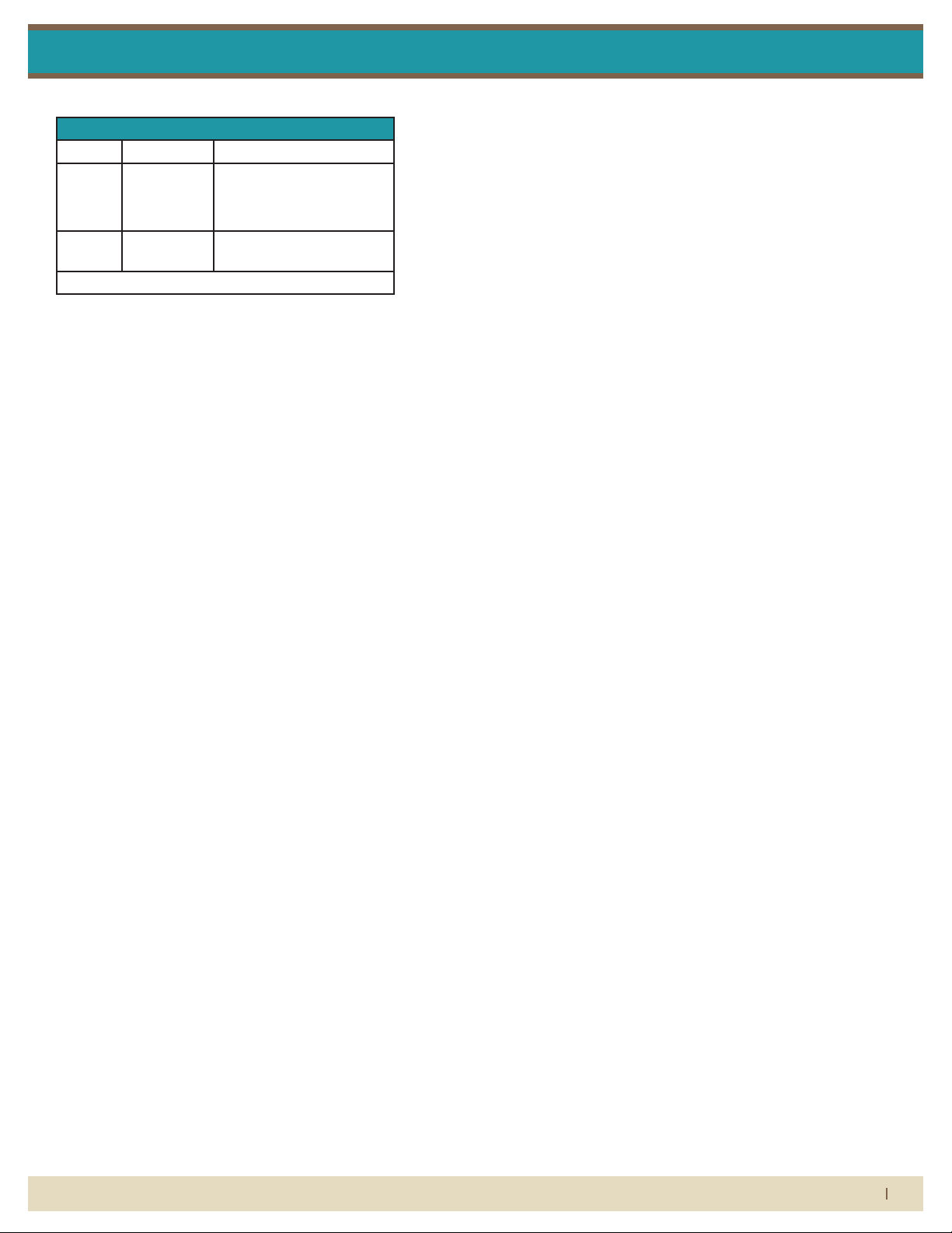
Maximum Non-Shock Pressure and Temperature
Fitting Temperature Pressure
316LSS 200°F 300 psig (31W-47W)
250 psig (51W-67W)
75 psig (81W-95W)
PVDF 200°F 150 psig (31W-67W)
75 psig (81W-95W)
Ambient Temp. 33° F -125° F
caution
• Silver Series meters have o-ring seals. Use with incompatible uids
may cause o-rings to swell which may cause glass tube to fail.
• Serious property damage and great personal injury could occur as
the result of a meter misused or used in an unsuitable application.
cleaning
To minimize downtime, Silver Series metering tubes are designed
to be removed without uninstalling the owmeter from the piping
system. Meter should be drained prior to maintenance.
Remove the shield from the frame by loosening the 4 shield screws
with a 3/16” hex wrench. Loosen the scale plate screws and remove
the scale plate. Loosen the tube retainer screws and pull the tube
retainer forward. Rotate the glass tube to loosen the o-ring seal. Carefully push the glass tube up until its bottom clears the inlet tting.
Angle the bottom of the glass tube down and away from the frame.
Use caution. Pulling the glass tube at an extreme angle, or by excessive force will cause the tube to break. Do not allow the oat to fall.
Float damage may result in meter inaccuracy.
Inspect all parts for damage prior to re-assembly. Replacement of
o-rings during meter maintenance is recommended. O-rings should
be generously lubricated using a silicone based o-ring lubricant. Insert
the oat and oat stops into the glass tube. Make sure the orientation
of the oat is correct prior to installing. Carefully slide glass tube assembly onto top tting at a slight angle and align with bottom tting.
Secure the tube by pushing the tube retainer between the glass tube
and the upper tting and tighten the screws. Replace the scale plate
making sure the reference line on the scale is aligned with the reference line on the glass tube. Re-install the front shield.
*Do not use cleaning agents that will damage oat, tube or o-rings.
Meters should be cleaned with a mild soap solution. This will be an
eective cleaner of rust stains. Caution must be used so that materials
of construction are not damaged by cleaning solutions. Hard water
deposIts can be removed with 5% acetic acid solution (vinegar).
repair
Silver Series meters that require repair should be sent to the factory.
Please call for a Return Merchandise Authorization (RMA) number and
return instructions
warning:
Pressure and temperature ratings are based on a study of the engineering data for particular materials used in construction and on the
design of individual models. This information is supplemented by
destructive test results. Meters with stainless enclosures must never be
operated without shields securely in place. Meters exposed to dicult
environments such as those created by certain chemicals, excessive
vibration or other stress inducing factors could fail at or below the
suggested maximums. Never operate meters above pressure and
temperature maximums. It is strongly recommended that all meter
installations utilize an appropriate pressure relief valve and/or rupture
disc. The pressure settings and locations of these devices should be
such that meters cannot be over pressurized. Meter failure could
result in damage to equipment and serious personal injury. Always
use suitable safety gear, including OSHA approved eye protection
when working around meters in service. We are happy to pass along
chemical compatibility information that has been published by the
manufacturer’s of raw materials used in our products; however, this
information should not be construed as a recommendation made by
King Instrument Company, Inc. for a specic application.
When it comes to ow...we’re instrumental.
(714) 891-0008 • www.kinginstrumentco.com
2
Page 3

Silver Series
silver series asseMbly
parts list:
1. End Fitting Retainer Screw
2. End Fitting Retainer
Split Washer
3. End Fitting Retainer
4. Outlet End Fitting
5. End Fitting O-Ring
6. Case
7. Outlet Float Stop
8. Float
9. Glass Meter Tube
10. Inlet Float Stop
11. Glass Tube Saver
Installation Instructions
12. Tube Retainer
13. Inlet End Fitting
14. Tube Retainer Screw
15. Upper Scale Plate Bracket
16. Lower Scale Plate Bracket
17. Scale Plate Bracket Screw
4X
4X
18. Scale Plate
19. Scale Plate Screw
20. Shield
21. Shield Flat Washer
22. Shield Screw
2X
2X
4X
4X
4X
4X
When it comes to ow...we’re instrumental.
(714) 891-0008 • www.kinginstrumentco.com
3
Page 4

Pressure and temperature ratings are based on a study of the engineering data for
particular materials used in construction and on the design of individual models.
This information is supplemented by destructive test results. Meters with stainless
enclosures must never be operated without shields securely in place. Meters
exposed to difficult environments such as those created by certain chemicals,
excessive vibration or other stress inducing factors could fail at or below the
suggested maximums. Never operate meters above pressure and temperature
maximums. It is strongly recommended that all meter installations utilize an
appropriate pressure relief valve and/or rupture disc. The pressure settings and
locations of these devices should be such that meters cannot be over pressurized.
Meter failure could result in damage to equipment and serious personal injury.
Always use suitable safety gear, including OSHA approved eye protection when
working around meters in service. We are happy to pass along chemical
Remove the shield from the frame by loosening the 4 shield screws with a
wrench. Loosen the scale plate screws and remove the scale plate. Loosen the
tube retainer screws and pull the tube retainer forward. Rotate the glass tube to
loosen the o-ring seal. Carefully push the glass tube up until its bottom clears the
inlet fitting. Angle the bottom of the glass tube down and away from the frame. Use
caution. Pulling the glass tube at an extreme angle, or by excessive force will
cause the tube to break. Do not allow the float to fall. Float damage may result in
meter inaccuracy.
Inspect all parts for damage prior to re-assembly. Replacement of o-rings during
meter maintenance is recommended. O-rings should be generously lubricated
using a silicone based o-ring lubricant. Insert the float and float stops into the glass
tube. Make sure the orientation of the float is correct prior to installing. Carefully
slide glass tube assembly onto top fitting at a slight angle and align with bottom
fitting. Secure the tube by pushing the tube retainer between the glass tube and the
upper fitting and tighten the screws. Replace the scale plate making sure the
referrence line on the scale is aligned with the reference line on the glass tube.
Re-install the front shield.
*Do not use cleaning agents that will damage float, tube or o-rings.
Meters should be cleaned with a mild soap solution. This will be an effective
cleaner of rust stains. Caution must be used so that materials of construction are
not damaged by cleaning solutions. Hard water deposits can be removed with 5%
acetic acid solution (vinegar).
Silver Series meters that require repair should be sent to the factory. Please call for
a Return Merchandise Authorization (RMA) number and return instructions.
-Serious property damage and great personal injury could occur as the result of a
meter misused or used in an unsuitable application.
CAUTION:
CLEANING:
REPAIR:
WARNING:
All Silver Series flowmeters may be fitted with one or two latching reed switches.
The switch assembly is mounted on the scale plate. The switch can be positioned
to trip at any point on the scale.
The switch is a reed type and uses a biasing magnet to give it the latching feature.
The float contains hermetically sealed magnet(s), so when the float comes in
SPST
4W Max.
30V DC Max.
200V DC Min.
0.2A Max.
0.020 Ohm Max. @ 50% magnetic overdrive
1 (+) High Switch
2 (-)
1 (+)
2 (-)
Low Switch 4 (+)
5 (-)
-Silver Series meters have o-ring seals. Use with incompatible fluids may cause
o-rings to swell which may cause glass tube to fail.
To minimize downtime, Silver Series metering tubes are designed to be removed
without uninstalling the flowmeter from the piping system. Meter should be drained
prior to maintenance.
Pressure and temperature ratings are based on a study of the engineering data for
particular materials used in construction and on the design of individual models.
This information is supplemented by destructive test results. Meters with stainless
enclosures must never be operated without shields securely in place. Meters
exposed to difficult environments such as those created by certain chemicals,
excessive vibration or other stress inducing factors could fail at or below the
suggested maximums. Never operate meters above pressure and temperature
maximums. It is strongly recommended that all meter installations utilize an
appropriate pressure relief valve and/or rupture disc. The pressure settings and
locations of these devices should be such that meters cannot be over pressurized.
Meter failure could result in damage to equipment and serious personal injury.
Always use suitable safety gear, including OSHA approved eye protection when
working around meters in service. We are happy to pass along chemical
Remove the shield from the frame by loosening the 4 shield screws with a
3
16
" hex
wrench. Loosen the scale plate screws and remove the scale plate. Loosen the
tube retainer screws and pull the tube retainer forward. Rotate the glass tube to
loosen the o-ring seal. Carefully push the glass tube up until its bottom clears the
inlet fitting. Angle the bottom of the glass tube down and away from the frame. Use
caution. Pulling the glass tube at an extreme angle, or by excessive force will
cause the tube to break. Do not allow the float to fall. Float damage may result in
meter inaccuracy.
Inspect all parts for damage prior to re-assembly. Replacement of o-rings during
meter maintenance is recommended. O-rings should be generously lubricated
using a silicone based o-ring lubricant. Insert the float and float stops into the glass
tube. Make sure the orientation of the float is correct prior to installing. Carefully
slide glass tube assembly onto top fitting at a slight angle and align with bottom
fitting. Secure the tube by pushing the tube retainer between the glass tube and the
upper fitting and tighten the screws. Replace the scale plate making sure the
referrence line on the scale is aligned with the reference line on the glass tube.
Re-install the front shield.
*Do not use cleaning agents that will damage float, tube or o-rings.
Meters should be cleaned with a mild soap solution. This will be an effective
cleaner of rust stains. Caution must be used so that materials of construction are
not damaged by cleaning solutions. Hard water deposits can be removed with 5%
acetic acid solution (vinegar).
Silver Series meters that require repair should be sent to the factory. Please call for
a Return Merchandise Authorization (RMA) number and return instructions.
-Serious property damage and great personal injury could occur as the result of a
meter misused or used in an unsuitable application.
CAUTION:
CLEANING:
REPAIR:
WARNING:
SPST
4W Max.
30V DC Max.
200V DC Min.
0.2A Max.
0.020 Ohm Max. @ 50% magnetic overdrive
1 (+)
2 (-)
Low Switch 4 (+)
5 (-)
-Silver Series meters have o-ring seals. Use with incompatible fluids may cause
o-rings to swell which may cause glass tube to fail.
To minimize downtime, Silver Series metering tubes are designed to be removed
without uninstalling the flowmeter from the piping system. Meter should be drained
prior to maintenance.
Silver Series
Installation Instructions
latching reed switch
LATCHING REED SWITCH
All Silver Series owmeters may be tted with one or two latching
reed switches.
The switch assembly is mounted on the scale plate. The switch can be
positioned to trip at any point on the scale.
The switch is a reed type and uses a biasing magnet to give it the
latching feature. The oat contains hermetically sealed magnet(s), so
when the oat comes in proximity to the switch it closes and remains
closed (latched) when the oat moves below the switch it resets itself.
Contact King Instrument Company for multiple switch options.
latching reed switch-electrical
speciFications
TYPE: SPST
POWER: 4W Max.
SWITCHING VOLTAGE: 30V DC Max.
BREAKDOWN VOLTAGE: 200V DC Min.
SWITCHING CURRENT: 0.2A Max.
CARRY CURRENT: 1.4A Max.
INITIAL CONTACT RESISTANCE: 0.020 Ohm Max. @ 50%
magnetic overdrive
connections - intrinsically saFe wiring
Single Switch Dual Switch
1 (+) High Switch
2 (–) Low Switch
1(+)
2(–)
4(+)
5(–)
switch isolator option:
Latching reed switches can be used as stand alone devices, or may be
connected to a switch isolator for intrinsically safe applications. The
purpose of the switch isolator is to supply electrical signals between
safe and hazardous areas in either direction while limiting the amount
of energy that can be transferred even under fault conditions. Switch
isolators are available with 220VAC, 110VAC or 24VDC supply voltage
requirements, contain single pole double throw (SPDT) relays, and are
DIN rail mountable. See switch isolator specications for electrical connections and further details.
Float types and orientations
GV FLOAT
GS FLOAT BL FLOAT
LJ FLOAT
HF FLOAT
When it comes to ow...we’re instrumental.
(714) 891-0008 • www.kinginstrumentco.com
4
Page 5

Silver Series
silver series asseMbly with alarM
parts list:
1. Meter Assembly
2. Alarm Switch Assembly
3. Alarm Switch Assembly Screw
4. Alarm Connector Plug
5. Ground Nut
6. Ground Lock Washer
7. Alarm Switch Housing Wing Nut
8. Alarm Switch Housing
9. Alarm Switch Housing Set Screw
10. Alarm Scale Plate
Installation Instructions
11. Alarm Scale Plate Screw
12. Shield
13. Shield Flat Washer
14. Shield Screw
4X
4X
When it comes to ow...we’re instrumental.
2X
(714) 891-0008 • www.kinginstrumentco.com
5
 Loading...