

Page 1
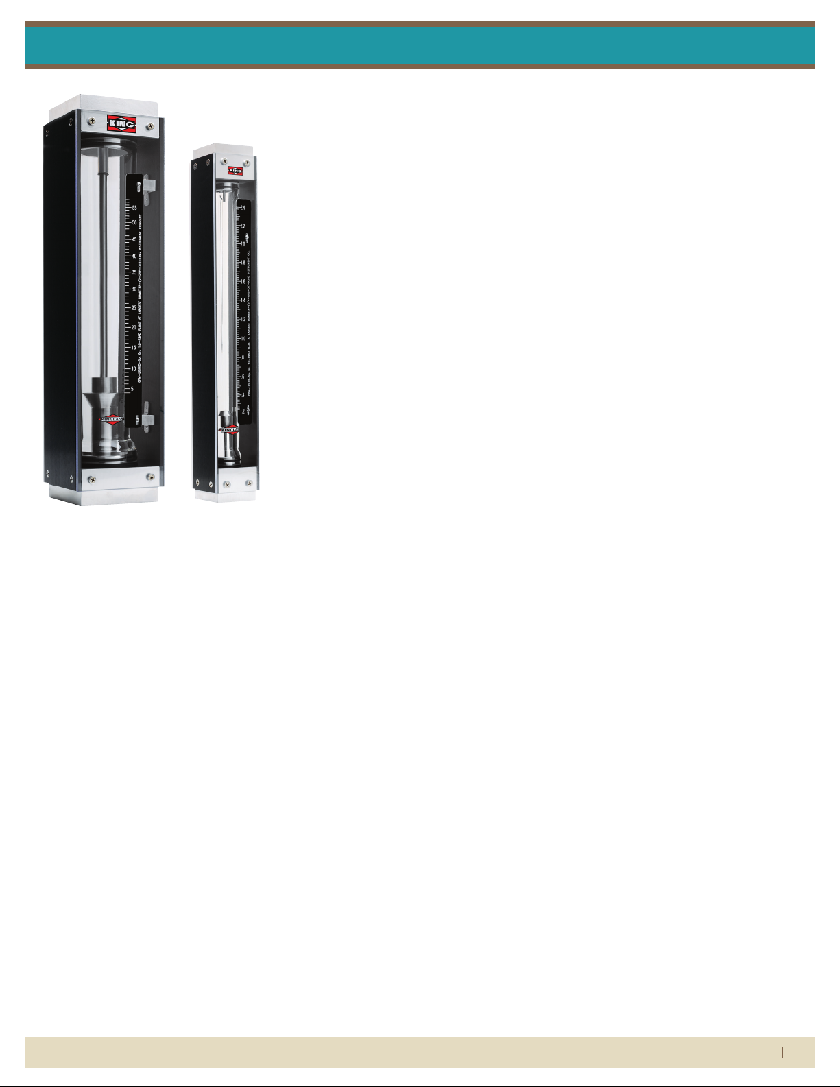
7459 Series
Installation Instructions
Flow Meter liMited warranty
Meters are warranted against defects in materials and workmanship to the original user for a
period of thirteen (13) months from the date of factory shipment, provided the meter is installed,
operated and maintained in accordance with King Instrument Company’s instructions and recommendations.
This warranty does not apply if failure is caused or contributed to by any of the following: improper handling, improper storage, abuse, unsuitable application of the product, lack of reasonable and necessary maintenance, use exceeding suggested pressure and temperature maximums,
improper packaging for return, or repairs made or attempted to be made by anyone other than
King Instrument Company, Inc.
KING INSTRUMENT COMPANY, INC. MAKES NO WARRANTY AS TO THE FITNESS OF ITS PRODUCTS
FOR SPECIFIC APPLICATIONS.
This warranty is valid for the original end-user only and does not apply to products that have been
damaged or modied. This warranty is non-transferrable and is limited to replacement or repair.
The liability of King Instrument Company arising out of its supply of the products, or their use, shall
not in any case exceed the cost of correcting defects in the products as set forth above.
THIS WARRANTY IS A LIMITED WARRANTY AND SHALL BE IN LIEU OF ANY OTHER WARRANTIES, EXPRESSED OR IMPLIED, INCLUDING BUT NOT LIMITED TO ANY IMPLIED WARRANTY OR MERCHANTABILITY OR FITNESS FOR A PARTICULAR PURPOSE. THERE ARE NO OTHER WARRANTIES WHICH
EXIST BEYOND THE DESCRIPTION OR FACE HEREOF.
IN NO EVENT SHALL KING INSTRUMENT COMPANY BE LIABLE FOR LOSS OF PROFITS, INDIRECT,
CONSEQUENTIAL OR INCIDENTAL DAMAGES.
Products should be returned, prepaid, to King Instrument Company, Inc. with proof of purchase.
Call factory for Return Merchandise Authorization (RMA) number and return instructions.
this is iMportant inForMation.
read it careFully beFore beginning work.
1) Inspect meter for damage that may have occurred during shipping.
Report any damage to the container to the freight carrier immediately.
2) Make sure your pressure, temperature, uid and other requirements
are compatible with the meter (including o-rings.)
3) Select a suitable location for installation to prevent excess stress on
the meter which may result from:
a) Misaligned pipe.
b) The weight of related plumbing.
c) “Water Hammer” which is most likely to occur when ow is
suddenly stopped as with quick closing solenoid operated
valves. (If necessary, a surge chamber should be installed. This
will also be useful in pressure start-up situations.)
d) Thermal expansion of liquid in a stagnated or valve isolated
system.
e) Instantaneous pressurization which will stress the meter and
could result in tube failure.
note: In closed thermal transfer or cooling systems, install the meter
in the cool side of the line to minimize meter expansion and contraction and possible uid leaks at the threaded connections.
4) Handle the meter carefully during installation.
a) Use an appropriate amount of teon tape on external pipe
threads before making connections. Do not use paste or stick
type thread sealing products.
b) Over tightening of plastic connections may result in tting
damage.
5) Install the meter vertically with the inlet port at the bottom.
6) Connections: Fittings are fully rotatable by loosening the tting
retainer screws during installation. Make sure tting retainer screws
are tightening after adjustment of tting
7) Meters with stainless steel ttings will support several feet of pipe
as long as signicant vibration or stress resulting from misaligned pipe
are not factors.
8) Meters with plastic ttings must be installed so that ttings are not
made to support any part of the associated plumbing. In addition,
meter frame should be fastened to bulkhead, panel or column.
9) Meters used in gas service should have suitable valves plumbed in
at the inlet and outlet of the meter. These valves should be no more
than 1-1/2 pipe diameters from the meter ports. The valve at the outlet should be used to create back pressure as required to prevent oat
bounce. It should be set initially and then left alone. The inlet valve
should be used for throttling purposes. Depending on the installation,
valves may not be essential, but they are most useful in many installations. Remember: To get a correct reading of ow in gas service, it is
necessary to know the pressure right at the outlet of the meter (before
the valve).
When it comes to ow...we’re instrumental.
(714) 891-0008 • www.kinginstrumentco.com
1
Page 2
7459 Series
-O-rings should be replaced if meter is disassembled after it has been in service.
-Serious property damage and great personal injury could occur as the result of a
meter misused or used in an unsuitable application.
CAUTION:
CLEANING:
Carefully remove the flowmeter from piping system. Remove the 4 screws on each
side holding the side plates on. Remove the 4 screws on each side holding the
front and rear shields on. Remove the side plates and shields. Carefully remove the
-O-rings should be replaced if meter is disassembled after it has been in service.
-Serious property damage and great personal injury could occur as the result of a
meter misused or used in an unsuitable application.
CAUTION:
CLEANING:
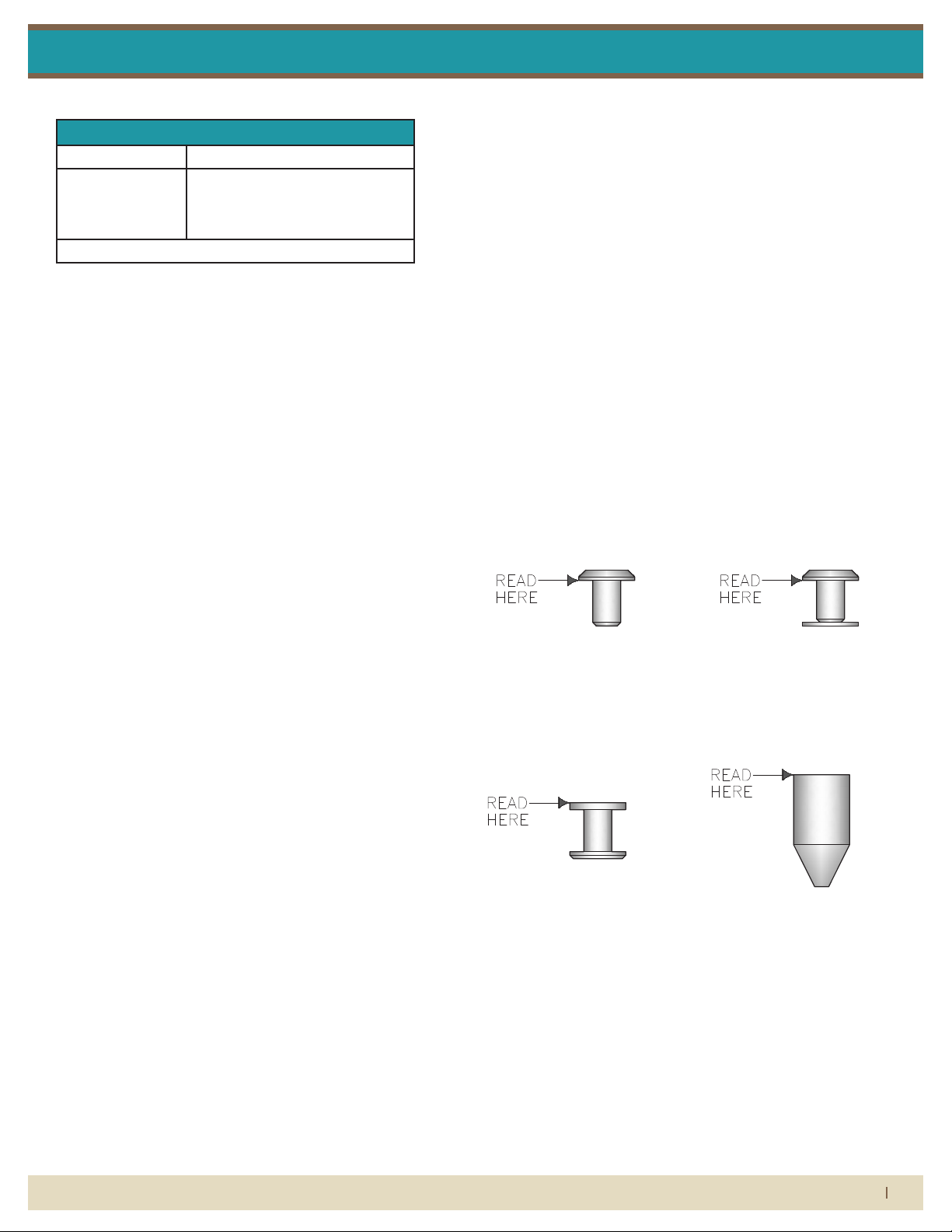
GV FLOAT (RIB GUIDED)
Highest immunity to viscous
fluids with medium meter
capacity.
Carefully remove the flowmeter from piping system. Remove the 4 screws on each
side holding the side plates on. Remove the 4 screws on each side holding the
front and rear shields on. Remove the side plates and shields. Carefully remove the
glass meter tube from the end fittings. Be sure to not let the internals fall out. Use
caution when removing the glass meter tube. Do not allow float to fall out. Float
damage may result in inaccuracy. All necessary instrument components are now
fully accessible for cleaning with a bottle brush and appropriate mild soap solution*.
Before the meter is reassembled, inspect all parts for damage. O-rings should be
replaced during meter maintenance and cleaning.
To reassemble, install the glass meter tube back onto the end fittings. Reinstall the
side plates and shields. Tighten the 4 screws on each side and front and back.
Reinstall the instrument into the plumbing system after removing the old teflon tape
(with a wire brush) and replacing with fresh teflon tape.
*Do not use cleaning agents that will damage float, tube or o-rings.
Meters should be cleaned with a mild soap solution. This will be an effective
cleaner of rust stains. Caution must be used so that materials of construction are
not damaged by cleaning solutions. Hard water deposits can be removed with 5%
acetic acid solution (vinegar).
GV FLOAT (POLE GUIDED)
Highest immunity to viscous
fluids with medium meter
capacity.
Installation Instructions
Maximum Non-Shock Pressure and Temperature
Temperature Pressure
200° F (Liquid)
250° F (Gas)
Ambient Temp. 33° F -125° F
caution
• O-rings should be replaced if meter is disassembled after it has been
in service.
• Serious property damage and great personal injury could occur as
the result of a meter misused or used in an unsuitable application.
cleaning
Carefully remove the owmeter from piping system. Remove the 4
screws on each side holding the side plates on. Remove the 4 screws
on each side holding the front and rear shields on. Remove the side
plates and shields. Carefully remove the glass meter tube from the end
ttings. Be sure to not let the internals fall out. Use caution when removing the glass meter tube. Do not allow oat to fall out. Float damage may result in inaccuracy. All necessary instrument components are
now fully accessible for cleaning with a bottle brush and appropriate
mild soap solution*. Before the meter is reassembled, inspect all parts
for damage. O-rings should be replaced during meter maintenance
and cleaning.
*Do not use cleaning agents that will damage oat, tube or o-rings.
To reassemble, install the glass meter tube back onto the end ttings.
Reinstall the side plates and shields. Tighten the 4 screws on each side
and front and back. Reinstall the instrument into the plumbing system
after removing the old teon tape (with a wire brush) and replacing
with fresh teon tape.
Meters should be cleaned with a mild soap solution. This will be an
eective cleaner of rust stains. Caution must be used so that materials
of construction are not damaged by cleaning solutions. Hard water
deposits can be removed with 5% acetic acid solution (vinegar).
repair
7459 meters that require repair should be sent to the factory. Please
call for a Return Merchandise Authorization (RMA) number and return
instructions.
When it comes to ow...we’re instrumental.
350 psig (31W-46W)
175 psig (51W-56W)
125 psig (61W-98W)
warning:
Pressure and temperature ratings are based on a study of the engineering data for particular materials used in construction and on the
design of individual models. This information is supplemented by
destructive test results. Meters with stainless enclosures must never be
operated without shields securely in place. Meters exposed to dicult
environments such as those created by certain chemicals, excessive
vibration or other stress inducing factors could fail at or below the
suggested maximums. Never operate meters above pressure and
temperature maximums. It is strongly recommended that all meter
installations utilize an appropriate pressure relief valve and/or rupture
disc. The pressure settings and locations of these devices should be
such that meters cannot be over pressurized. Meter failure could
result in damage to equipment and serious personal injury. Always
use suitable safety gear, including OSHA approved eye protection
when working around meters in service. We are happy to pass along
chemical compatibility information that has been published by the
manufacturer’s of raw materials used in our products; however, this
information should not be construed as a recommendation made by
King Instrument Company, Inc. for a specic application.
Float types and orientations
GV FLOAT
(Rib Guided)
GV FLOAT
(Pole Guided)
LP FLOAT
SL FLOAT
(714) 891-0008 • www.kinginstrumentco.com
2
Page 3

7459 Series
4X
2X
2X
4X 4X
2X
Installation InstructionsInstallation Instructions
7459 series asseMbly
rib guided tube
parts list:
4X
4X
2X
4X
1. End Fitting Block
2. O-Ring
3. Glass Tube Gasket
4. Float Stop/Extension Assembly
5. Float
6. Glass Meter Tube
7. Inlet Float Stop/Extension Assembly
8. Side Plate/ Sheild Screw
9. Side Plate
10. Scale Side Plate
11. Shield (Clear)
12. Shield (White)
13. Scale Bracket Screw
14. Scale Bracket
15. Scale Plate Screw
16. Scale Plate
7459 series asseMbly
pole guided tube
parts list:
1. End Fitting Block
2. O-Ring
3. Glass Tube Gasket
4. Float Stop/Guide Rod Assembly
5. Float
6. Glass Meter Tube
7. Inlet Float Stop
8. Side Plate/Shield Screw
9. Side Plate
10. Scale Side Plate
11. Shield (Clear)
12. Shield (White)
13. Scale Bracket Screw
14. Scale Bracket
15. Scale Plate Screw
16. Scale Plate
4X4X
4X
2X
2X
2X
When it comes to ow...we’re instrumental.
(714) 891-0008 • www.kinginstrumentco.com
3
 Loading...