

Page 1
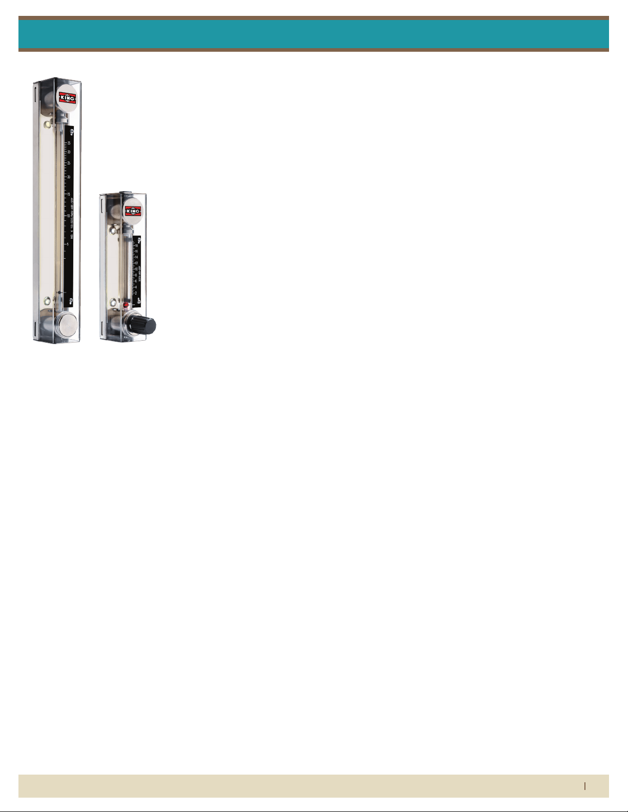
7430 Series Hastelloy / Monel / Stainless Steel
FLOW METER LIMITED WARRANTY
Meters are warranted against defects in materials and workmanship to the original user for a period of thirteen (13) months from the date of factory shipment, provided the meter is installed, operated and maintained
in accordance with King Instrument Company’s instructions and recommendations.
This warranty does not apply if failure is caused or contributed to by any of the following: improper handling,
improper storage, abuse, unsuitable application of the product, lack of reasonable and necessary maintenance, use exceeding suggested pressure and temperature maximums, improper packaging for return, or
repairs made or attempted to be made by anyone other than King Instrument Company, Inc.
KING INSTRUMENT COMPANY, INC. MAKES NO WARRANTY AS TO THE FITNESS OF ITS PRODUCTS FOR SPECIFIC
APPLICATIONS.
This warranty is valid for the original end-user only and does not apply to products that have been damaged
or modied. This warranty is non-transferrable and is limited to replacement or repair. The liability of King Instrument Company arising out of its supply of the products, or their use, shall not in any case exceed the cost
of correcting defects in the products as set forth above.
THIS WARRANTY IS A LIMITED WARRANTY AND SHALL BE IN LIEU OF ANY OTHER WARRANTIES, EXPRESSED OR
IMPLIED, INCLUDING BUT NOT LIMITED TO ANY IMPLIED WARRANTY OR MERCHANTABILITY OR FITNESS FOR A
PARTICULAR PURPOSE. THERE ARE NO OTHER WARRANTIES WHICH EXIST BEYOND THE DESCRIPTION OR FACE
HEREOF.
IN NO EVENT SHALL KING INSTRUMENT COMPANY BE LIABLE FOR LOSS OF PROFITS, INDIRECT, CONSEQUENTIAL OR INCIDENTAL DAMAGES.
Products should be returned, prepaid, to King Instrument Company, Inc. with proof of purchase. Call factory
Hastelloy / Monel /
Stainless Steel
for Return Merchandise Authorization (RMA) number and return instructions.
Installation Instructions
THIS IS IMPORTANT INFORMATION.
READ IT CAREFULLY BEFORE BEGINNING WORK.
1) Inspect meter for damage that may have occurred during shipping.
Report any damage to the container to the freight carrier immediately.
2) Make sure your pressure, temperature, uid and other requirements
are compatible with the meter (including o-rings.)
3) Select a suitable location for installation to prevent excess stress on
the meter which may result from:
a) Misaligned pipe.
b) The weight of related plumbing.
c) “Water Hammer” which is most likely to occur when ow is
suddenly stopped as with quick closing solenoid operated
valves. (If necessary, a surge chamber should be installed. This
will also be useful in pressure start-up situations.)
d) Thermal expansion of liquid in a stagnated or valve isolated
system.
e) It is recommended to install valving which will allow the meter
to be drained. Meter should be drained when not in use or
prior to maintenance.
f) Instantaneous pressurization which will stress the meter and
could result in tube failure.
NOTE: In closed thermal transfer or cooling systems, install the meter
in the cool side of the line to minimize meter expansion and contraction and possible uid leaks at the threaded connections.
4) Handle the meter carefully during installation.
a) Use an appropriate amount of teon tape on external pipe
threads before making connections. Do not use paste or stick
type thread sealing products.
5) Install the meter vertically with the inlet port at the bottom.
6) Meters with stainless steel ttings will support several feet of pipe
as long as signicant vibration or stress resulting from misaligned pipe
are not factors.
7) Meters used in gas service should have suitable valves plumbed in
at the inlet and outlet of the meter. These valves should be no more
than 1-1/2 pipe diameters from the meter ports. The valve at the outlet should be used to create back pressure as required to prevent oat
bounce. It should be set initially and then left alone. The inlet valve
should be used for throttling purposes. Depending on the installation,
valves may not be essential, but they are most useful in many installations. Remember: To get a correct reading of ow in gas service, it is
necessary to know the pressure right at the outlet of the meter (before
the valve).
8) Pressure and temperature maximums must never be exceeded.
When it comes to ow...we’re instrumental.
(714) 891-0008 • www.kinginstrumentco.com
1
Page 2
O-Ring
Temperature
EPR 225 °F
Buna-N
Viton
Kalrez
275 °F
350 °F
400 °F
200 psig
33° F - 125° F
O-Ring
Material
Maximum
Temperature
Pressure and temperature ratings are based on a study of the engineering data
for particular materials used in construction and on the design of individual
models. This information is supplemented by destructive test results. Meters with
stainless enclosures must never be operated without shields securely in place.
Meters exposed to difficult environments such as those created by certain
chemicals, excessive vibration or other stress inducing factors could fail at or
below the suggested maximums. Never operate meters above pressure and
temperature maximums. It is strongly recommended that all meter installations
utilize an appropriate pressure relief valve and/or rupture disc. The pressure
settings and locations of these devices should be such that meters cannot be
over pressurized. Meter failure could result in damage to equipment and serious
personal injury. Always use suitable safety gear, including OSHA approved eye
protection when working around meters in service. We are happy to pass along
chemical compatibility information that has been published by the manufacturer's
of raw materials used in our products; however, this information should not be
construed as a recommendation made by King Instrument Company, Inc. for a
specific application.
To minimize down time, 7430 Series metering tubes are designed to be removed
without uninstalling flowmeter from piping system. Meter should be drained prior
to maintenance.
7430 meters that require repair should be sent to the factory. Please call for a
Return Merchandise Authorization (RMA) number and return instructions.
-7430 Series meters have o-ring seals. Use with incompatible fluids may cause
o-rings to swell which may cause glass tube to fail.
-Plastic fittings are not suitable for gas applications.
-Extra caution must be exercised when meters are used in high pressure gas
cylinder applications. Pressure regulators should be installed at the cylinder and
at the inlet of the meter.
-Serious property damage and great personal injury could occur as the result of a
meter misused or used in an unsuitable application.
Carefully remove the flowmeter from the piping system. Remove the front shield
and the top frame plug. Insert a
1
8
" hex key through the top hole of the frame and
into the compression screw. Turn the hex key counter clockwise until the
compression screw is raised enough to be able to remove the glass tube.
Carefully remove the glass tube. Remove the compression screw by turning the
hex key clockwise. Float and float stops may be removed by inserting a rod into
one end of the glass tube and carefully pushing the components out the other
end.
All components are now fully accessible for cleaning. Components can be
cleaned with a mild soap solution. This will be an effective cleaner of rust stains.
A cotton swab may be helpful in cleaning the inside of the glass tube. Caution
must be used so that materials of construction are not damaged by cleaning
solutions. Hard water deposits can be removed with a 5% acetic acid solution
(vinegar). Before the meter is reassembled, inspect all parts for damage. O-rings
should be replaced during meter maintenance and cleaning.
To reassemble, insert bottom float stop into glass tube and push it down with a
rod. Insert the ball float and top float stop. Install the compression screw with the
1
8
" hex key, turning counter clockwise. Install the gaskets, seat bushing, and tube
adapters (
1
8
" float models only). Position glass tube in frame assembly and begin
to turn the compression screw clockwise. Make sure that the tube is centered and
that the reference line is facing frontward. Tighten compression screw to 4 in. lbs.
of torque. Re-install the frame orifice plug. Re-install valve assembly or valve
orifice plug. Replace shield by snapping it into place.
Valve Models: Remove valve from the bottom end fitting using a
7
16
" open ended
wrench. Disassembly of valve is not recommended. Outer valve o-ring should be
replaced during meter maintenance and cleaning. Prior to reinstalling valve, apply
blue Loctite to valve threads and a silicone based lubricant onto o-rings.
R
Non-Valve Models: Remove valve orifice plug from bottom end fitting by inserting
a
3
16
" hex key through the back of the end fitting and into the plug. Turn clockwise
to remove it.
7430 Series Hastelloy / Monel / Stainless Steel
Installation Instructions
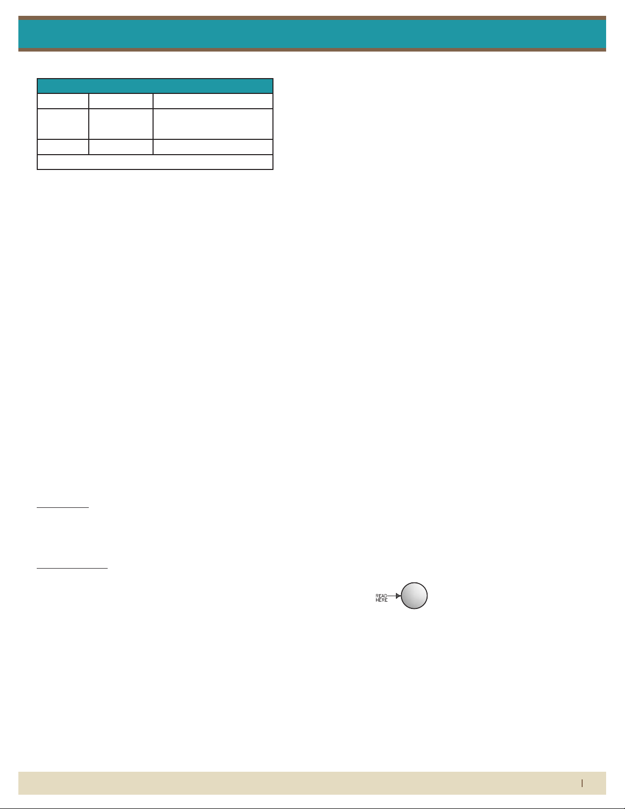
Maximum Non-Shock Pressure and Temperature
Temp Pressure
Liquid 200° F 200 (SS)
130 psig (PVC)
Gas 250° F 150 psig (PVDF)
Ambient Temp. 33° F -125° F
CAUTION
• 7430 Series meters have o-ring seals. Use with incompatible uid
may cause o-rings to swell which may cause glass tube to fail.
• Plastic ttings are not suitable for gas applications.
• Extra caution must be exercised when meters are used in high
pressure gas cylinder applications. Pressure regulators should be
installed at the cylinder and at the inlet of the meter.
• Serious property damage and great personal injury could occur as
the result of a meter misused or used in an unsuitable application.
CLEANING
To minimize down time, 7430 Series metering tubes are designed
to be removed without uninstalling owmeter from piping system.
Meter should be drained prior to maintenance.
Carefully remove the owmeter from the piping system. Remove the
front shield and the top frame plug. Insert a 5/32” hex key through the
top hole of the frame and into the compression screw. Turn the hex
key counter clockwise until the compression screw is raised enough
to be able to remove the glass tube. Carefully remove the glass tube.
Remove the compression screw by turning the hex key clockwise.
Float and oat stops may be removed by inserting a rod into one end
of the glass tube and carefully pushing the components out the other
end.
Valve Models: Remove valve from the bottom end tting using a
7/16” open ended wrench. Disassembly of valve is not recommended.
Outer valve o-ring should be replaced during meter maintenance
and cleaning. Prior to reinstalling valve, apply blue Loctite R to valve
threads and a silicone based lubricant onto o-rings.
Non-Valve Models: Remove valve orice plug from bottom end tting
by inserting a 3/16” hex key through the back of the end tting and
into the plug. Turn clockwise to remove it.
All components are now fully accessible for cleaning. Components
can be cleaned with a mild soap solution. This will be an eective
cleaner of rust stains. A cotton swab may be helpful in cleaning the
inside of the glass tube. Caution must be used so that materials of
construction are not damaged by cleaning solutions. Hard water
deposits can be removed with a 5% acetic acid solution (vinegar).
Before the meter is reassembled, inspect all parts for damage. O-rings
should be replaced during meter maintenance and cleaning.
To reassemble, insert bottom oat stop into glass tube and push it
down with a rod. Insert the ball oat and top oat stop. Install the
compression screw with the 5/32” hex key, turning counter clockwise.
Install the gaskets, seat bushing, and tube adapters (1/8” oat models
only). Position glass tube in frame assembly and begin to turn the
compression screw clockwise. Make sure that the tube is centered
and that the reference line is facing frontward. Tighten compression
screw to 4 in. lbs. of torque. Re-install the frame orice plug. Re-install
valve assembly or valve orice plug. Replace shield by snapping it
into place.
REPAIR
7430 meters that require repair should be sent to the factory. Please
call for a Return Merchandise Authorization (RMA) number and return
instructions.
WARNING:
Pressure and temperature ratings are based on a study of the
engineering data for particular materials used in construction and on
the design of individual models. This information is supplemented
by destructive test results. Meters with stainless enclosures must
never be operated without shields securely in place. Meters exposed
to dicult environments such as those created by certain chemicals,
excessive vibration or other stress inducing factors could fail at
or below the suggested maximums. Never operate meters above
pressure and temperature maximums. It is strongly recommended
that all meter installations utilize an appropriate pressure relief valve
and/or rupture disc. The pressure settings and locations of these
devices should be such that meters cannot be over pressurized.
Meter failure could result in damage to equipment and serious
personal injury. Always use suitable safety gear, including OSHA
approved eye protection when working around meters in service.
We are happy to pass along chemical compatibility information that
has been published by the manufacturer’s of raw materials used in
our products; however, this information should not be construed
as a recommendation made by King Instrument Company, Inc. for a
specic application.
FLOAT TYPES AND ORIENTATIONS
BL FLOAT
When it comes to ow...we’re instrumental.
(714) 891-0008 • www.kinginstrumentco.com
2
Page 3

2X
2X
2X
2X
7430 Series Hastelloy / Monel / Stainless Steel
7430 SERIES ASSEMBLY NON-VALVE
PARTS LIST:
Installation InstructionsInstallation Instructions
2X
2X
1. Top Frame Plug
2. Frame Assembly
3. Retaining Nut
4. O-Ring
5. Compression Screw
6. Seat Bushing
7. Glass Tube Gasket
8. Tube Adaptor
9. Float Stop
10. Float
11. Glass Meter Tube
12. End Fitting Plug
13. Scale Plate Mount Screw
14. Scale Plate Mount
15. Scale Plate Screw
16. Scale Plate
17. Shield
7430 SERIES ASSEMBLY INLET VALVE
OUTLET VALVE SIMILAR
PARTS LIST:
1. Top Frame Plug
2. Frame Assembly
3. Retaining Nut
4. O-Ring
5. Compression Screw
6. Seat Bushing
7. Glass Tube Gasket
8. Tube Adaptor
9. Float Stop
10. Float
11. Glass Meter Tube
12. Scale Plate Mount Screw
13. Scale Plate Mount
14. Scale Plate Screw
15. Scale Plate
16. Valve Assembly
17. Shield Spacer
18. Shield
When it comes to ow...we’re instrumental.
(714) 891-0008 • www.kinginstrumentco.com
3
Page 4

HOUSING RATING:
OFF STATE LEAKAGE CURRENT: 1 MICOAMP @ 30V DC
OUTPUT SATURATION VOLTAGE: <=1V at 10mA DC
REPEATABILITY: 0.25ms
OPERATING TEMPERATURE:
TOP FRAME PLUG
FRAME ASSEMBLY
GLASS METER TUBE ASSEMBLY
FIBER OPTIC HOUSING SCREW
FIBER OPTIC HOUSING
ALARM JUNCTION BOX SCREW
STRAIN CONNECTOR
FIBER OPTIC CABLE
FIBER OPTIC ADAPTOR
FIBER OPTIC SENSOR
SHIELD
2X
ALARM JUNCTION BOX
Inductive Proximity or Latching
5-25V DC (Switch Isolator)
NAMUR
<= 1mA-Float Present
>= 3mA (15mA Max.)-Float Absent
AWG, 6.5 Ft. Long.
Brown (+) / Blue (-)
Intrinsically Safe
UL:
FM:SENSOR APPROVALS:
Intrinsically SafeCSA:
Intrinsically SafeCENELEC:
-13°F to 104°F:
-13°F to 158°F:
1
8
" LATCHING
1
8
" PROXIMITY
1
4
" LATCHING
1
4
" PROXIMITY
7430 Series Hastelloy / Monel / Stainless Steel
7430 SERIES INDUCTIVE RING SENSOR
INDUCTIVE RING SENSOR:
All 7430 Series owmeters may be tted with one inductive ring sensor.
The inductive ring sensor is mounted on the glass meter tube using
springs to put tension between the frame and glass meter tube.
The sensor can be either proximity or latching type and can only be
used with 316SS or Carboloy oats. The inductive ring sensor produces
an electromagnetic eld that senses the metal oat within sensing
zone.
Inductive ring sensors are 2-wire, DC, low current devices and are designed to be used with a remote intrinsic safety barrier / switch isolator.
SWITCH ISOLATOR:
Inductive ring sensors are designed to be connected to a switch isolator
for intrinsically safe applications. The purpose of the switch isolator is
to supply electrical signals between safe and hazardous areas in either
direction while limiting the amount of energy that can be transferred
even under fault conditions. Switch isolators are available with 220VAC,
110VAC or 24VDC supply voltage requirements, contain single pole
double throw (SPDT) relays, and are DIN rail mountable. See switch
isolator specications for electrical connections and further details.
Installation InstructionsInstallation Instructions
INDUCTIVE RING SENSOR-ELECTRICAL
SPECIFICATIONS
TYPE: INDUCTIVE PROXIMITY OR
LATCHING
SUPPLY VOLTAGE: 5-25V DC (Switch Isolator)
OUTPUT: NAMUR
OUTPUT LOAD CURRENT: <= 1mA-Float Present
>= 3mA (15mA Max.)-Float Absent
SWITCHING FREQUENCY: 2kHZ
HOUSING RATING: IP67
OPERATING TEMPERATURE: -13°F to 104°F 1/8” Latching
-13°F to 158°F 1/8” Proximity
1/4” Latching
1/4” Proximity
WIRING: PVC covered, 2 Conductor,
26 AWG, 6.5 Ft. Long. Brown (+) / Blue (-)
PEPPERL+FUCHS UL: General Purpose
SENSOR APPROVALS FM: Intrinsically Safe
CSA: Intrinsically Safe
CENELEC: Intrinsically Safe
7430 SERIES ASSEMBLY
WITH INDUCTIVE RING SENSOR
PARTS LIST:
1. Top Frame Plug
2. Frame Assembly
3. Glass Meter Tube Assembly
4. Inductive Ring Sensor
5. Sensor Tension Spring
6. Alarm Junction Box
7. Alarm Junction Box Screw
8. Strain Connector
9. Shield
When it comes to ow...we’re instrumental.
(714) 891-0008 • www.kinginstrumentco.com
4
Page 5

12700 Pala Drive, Garden Grove, CA 92841
www.kinginstrumentco.com / (714) 891-0008
Meters are warranted against defects in materials and workmanship
to the original user for a period of thirteen (13) months from the date
of factory shipment, provided the meter is installed, operated and
maintained in accordance with King Instrument Company's
instructions and recommendations.
This warranty does not apply if failure is caused or contributed to by
any of the following: improper handling, improper storage, abuse,
unsuitable application of the product, lack of reasonable and
necessary maintenance, use exceeding suggested pressure and
temperature maximums, improper packaging for return, or repairs
made or attempted to be made by anyone other than King Instrument
Company, Inc.
KING INSTRUMENT COMPANY, INC. MAKES NO
WARRANTY AS TO THE FITNESS OF ITS PRODUCTS
FOR SPECIFIC APPLICATIONS.
This warranty is valid for the original end-user only and does not
apply to products that have been damaged or modified. This
warranty is non-transferrable and is limited to replacement or repair.
The liability of King Instrument Company arising out of its supply of
the products, or their use, shall not in any case exceed the cost of
correcting defects in the products as set forth above.
THIS WARRANTY IS A LIMITED WARRANTY AND
SHALL BE IN LIEU OF ANY OTHER WARRANTIES,
EXPRESSED OR IMPLIED, INCLUDING BUT NOT
LIMITED TO ANY IMPLIED WARRANTY OR
MERCHANTABILITY OR FITNESS FOR A PARTICULAR
PURPOSE. THERE ARE NO OTHER WARRANTIES
WHICH EXIST BEYOND THE DESCRIPTION OR FACE
HEREOF.
IN NO EVENT SHALL KING INSTRUMENT COMPANY BE
LIABLE FOR LOSS OF PROFITS, INDIRECT,
CONSEQUENTIAL OR INCIDENTAL DAMAGES.
Products should be returned, prepaid, to King Instrument Company,
Inc. with proof of purchase. Call factory for Return Merchandise
Authorization (RMA) number and return instructions.
IP67; NEMA 6
-5°F TO +131°F
7430 Series Hastelloy / Monel / Stainless Steel
7430 SERIES FIBER OPTIC SENSOR
FIBER OPTIC SENSOR:
All 7430 Series owmeters may be tted with one ber optic sensor.
The ber optic sensor is mounted to the frame with a screw in a slotted
screw for adjustability. The sensor uses a pair of ber optic cables with
an emitter and receiver to transmit the light generated by the sensor.
The sensor can interface directly to a Programmable Logic Controller (PLC) or when connected to a separate relay can trigger a local or
remote alarm.
Installation InstructionsInstallation Instructions
FIBER OPTIC SENSOR-ELECTRICAL SPECIFICATIONS
SUPPLY VOLTAGE: 10-30V DC
SUPPLY CURRENT: 25mA
OUTPUT: NPN Sinking, N.O. & N.C.
PNP Sourcing, N.O. & N.C.
OUTPUT RATING: 150mA max. Total Load
OUTPUT RESPONSE TIME: 1ms
OFF STATE LEAKAGE CURRENT: 1 MICOAMP @ 30V DC
OUTPUT SATURATION VOLTAGE: <=1V at 10mA DC
>=1.5V at 150mA DC
REPEATABILITY: 0.25ms
HOUSING RATING: IP67; NEMA 6
OPERATING TEMPERATURE: -5°F TO +131°F
7430 SERIES ASSEMBLY
WITH FIBER OPTIC SENSOR
PARTS LIST:
1. Top Frame Plug
2. Frame Assembly
3. Glass Meter Tube Assembly
4. Fiber Optic Housing Screw
5. Alarm Junction Box
6. Alarm Junction Box Screw
7. Strain Connector
8. Fiber Optic Cable
9. Fiber Optic Adaptor
10. Fiber Optic Sensor
11. Shield
When it comes to ow...we’re instrumental.
(714) 891-0008 • www.kinginstrumentco.com
5
 Loading...