

King-Gage Multi-Point Start-up And Operation Instructions
Multi-Point Process Switch EX-1711Effective: September 2006 (Replaces October 2002) EX-1711
®
KING-GAGE
4-20 mA Process Control
Multi-Point™ Process Switch
Single-Channel Analog
Start-Up/Operation
Instructions
Page 1

Multi-Point Process Switch EX-1711
© 1989/1995 King Engineering Corporation. All rights
reserved.
The information contained in this manual was accurate at
the time of release. Specifications are subject to change
without notice.
Warranty—All King Engineering products are guaranteed
to be free from defects in material and workmanship for
one year from the date of purchase. Any product or part
found to be defective under normal use within one year of
purchase will be repaired or replaced at no charge if returned
to the company at Ann Arbor, Michigan within ten days
of discovery of the defect. No other warranties, whether
expressed, implied or statutory, including the warranties
of fitness for a particular purpose or merchantability, are
given by this agreement.
The exclusive remedy for nonconformity of these goods
shall be repair and/or replacement of the nonconforming
goods or parts.
Seller will not be liable for consequential damages resulting
from breach of this agreement. The term “consequential
damages” shall include but shall not be limited to damage
to all machines, equipment and goods other than the goods
sold hereby, interruption of production, loss of profits,
delays of any kind, administrative expense and overhead.
Revisions:
(A) October, 1989—Original Release.
(B) December, 1989—Revised Deadband Range
(C) April, 1995—Revised/Redrawn per ECR No. 3397
(D) October, 2002—Logo w/ web address (cover)
(E) September, 2006—Heading (cover), logo (back)
Page 2

Multi-Point Process Switch EX-1711
Contents
Specifications
Specification Data, Dimensions ............................................................................. 4
AC Power Requirements
Power Terminal Connections ................................................................................. 5
Internal Fuse Replacement .................................................................................... 6
4-20 mA Process Loop
Typical Process Loop Diagram................................................................................7
Input Current Limiting (PTC Resistor).....................................................................7
Set-Points/Output Relays
Front Panel—LED Status Indicators........................................................................8
3.0 Amp SPDT Relays ............................................................................................ 8
Set-Point Adjustments .......................................................................................... 9
Deadband Adjustment .......................................................................................... 10
Troubleshooting
Symptoms and Possible Causes ............................................................................. 11
Page 3
®
KING-GAGE
S
E
T
1
S
E
T
2
S
E
T
3
S
E
T
4
MULTI-POINT
Process Switch
1
2
3
4
Coarse Adj.
Fine Adj.
Coarse Adj.
Fine Adj.
Coarse Adj.
Fine Adj.
Coarse Adj.
Fine Adj.
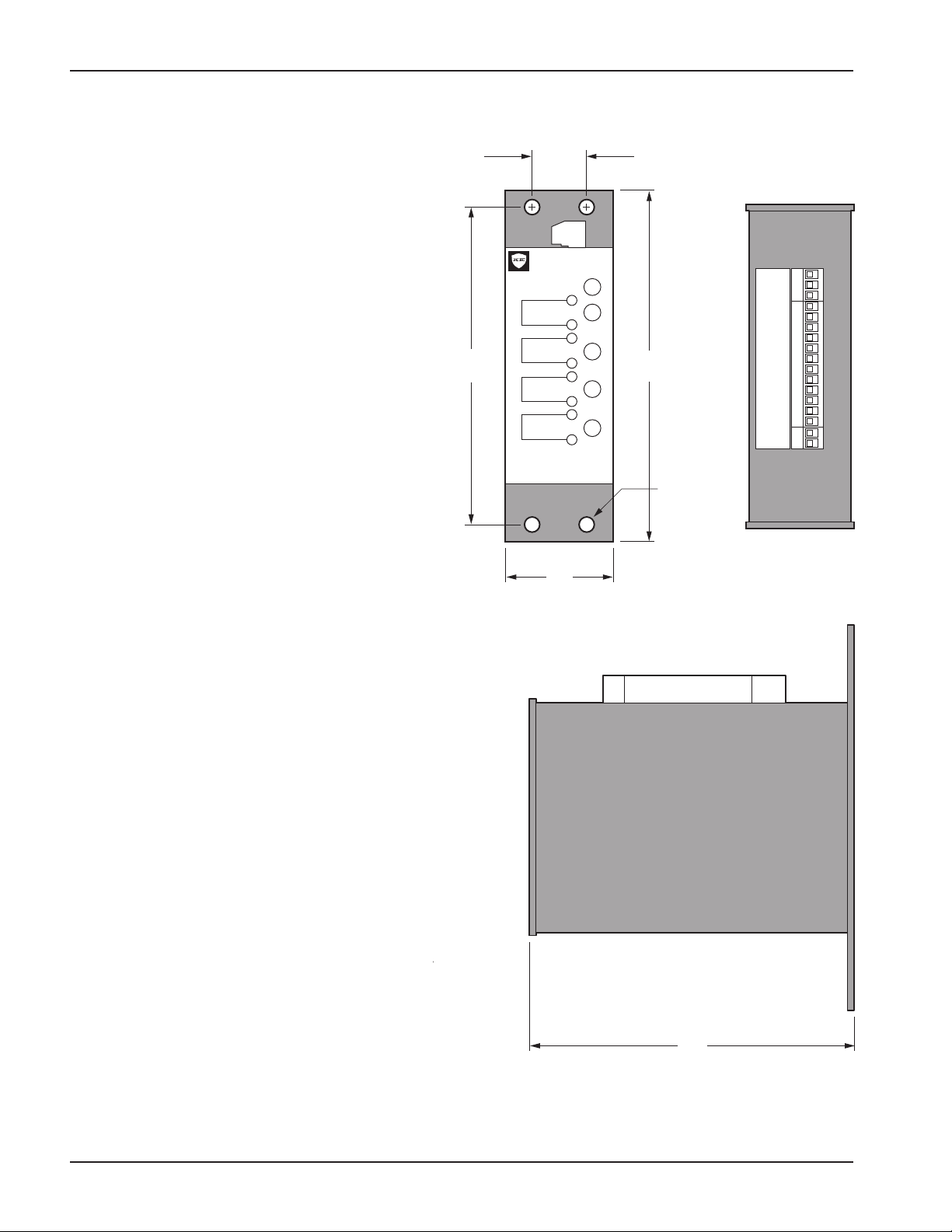
2 in
51 mm
6 in
152 mm
7-1/8 in.
181 mm
6-1/2 in.
165 mm
POWER
Hot
Gnd
Neu
C
N.O.
N.C.
C
N.O.
N.C.
C
N.O.
N.C.
C
N.O.
N.C.
+
-
INPUT
4-20 mA
AC
115 V
S
E
T
1
S
E
T
2
S
E
T
3
S
E
T
4
9/32 in.
7 mm, qty. 4
1-1/16 in.
27 mm
Multi-Point Process Switch EX-1711
Specifications
Power Requirements
nominal 115 Vac/60 Hz (unregulated)
3.45 W/0.03 A - fused @ 1/2 A
Temperature Range (Environmental)
32° F to 158° F / 0° C to 70° C operating
(-40° F to 158° F / - 40° C to 70° C storage)
Input
dc current: 4-20 milliamperes
Current Limiting (Overload)
70 mAdc maximum; automatic trip/reset using
PTC resistor (positive temperature coefficient)
circuit
Input Impedance
132 ohm resistance (3 Vdc drop @ 20 mAdc)
Set-Points
(4) four independent user set-points; continuously
adjustable over full input range. Front panel LED
status indicator gives visual confirmation when set point value has been exceeded.
Sensitivity (Adjustment)
Set-points can be adjusted to better than
0.05% FS/ 0.008 mAdc
Repeatability
Set-point settings are repeatable to better than
0.05% FS
(Long-Term Repeatability: better than 0.1% FS)
Deadband
Single deadband potentiometer controls all four set-
point settings. Deadband adjustable from 1.0% -
12.5% FS. (Factory preset to 1% FS.)
Output
(4) independent SPDT (form-C) relays; maximum
3.0 A @ 115 Vac. Rated for minimum 100,000 cycle/
life at rated load.
Size/Weight
7.125"H × 2"W × 6.125"D
(181mm × 51mm × 155mm)
22 oz/624 g
Page 4
 Loading...