

Kingfisher Controls M3, M4 Data Sheet
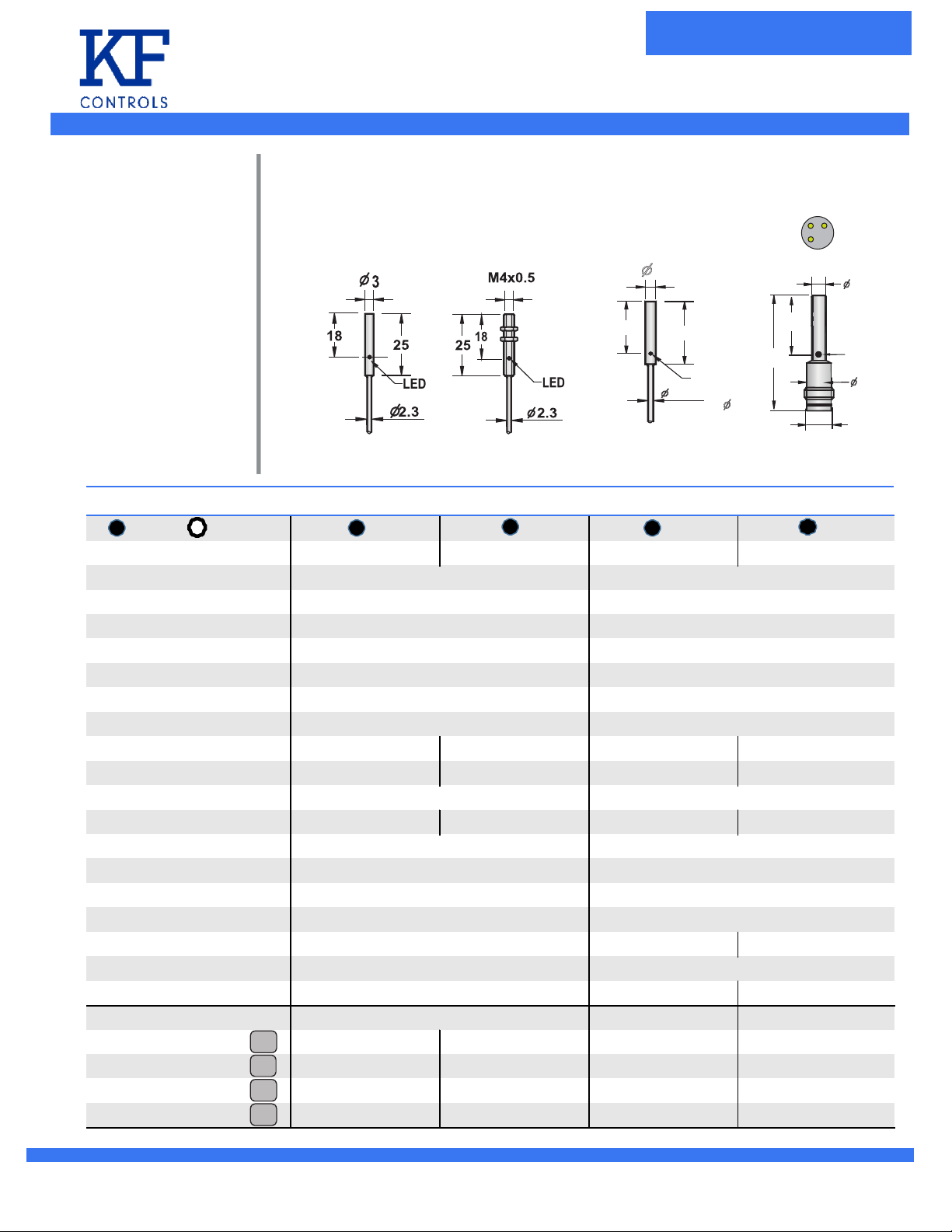
Diameter ø3mm 4mm ø4mm ø4mm - Pico 3-Pin
Inductive-Standard
Inductive-Miniature
ProximityProximity
19
φ
4
25
LED
φ
2.7
2.7 3x0.15
M3, M4
19
40
φ
3-Wire DC Inductive
Flush Non-fl ush
Switching Distance Sn:mm 0.6mm 0.6mm 0.8mm 0.8mm
LED Indicator
Opera ting Voltage
Ripple
No Load Current
Max Loa d Curre nt
Leaka ge Curre nt
Volta ge Drop
Switching Frequency 2 KHz 2 KHz 2 KHz 2 KHz
Res pons e Time 0.2ms/0.2ms 0.2ms/0.2ms 0.2ms/0.2ms 0.2ms/0.2ms
Switching Hysteres is
Repe at Accuracy <2%(Sr) <2%(Sr) <2%(Sr) <2%(Sr)
Enclosure Rating
Opera ting Tempera ture
Temperature Drift
Protection
Conne ction Type 3-wire , 2-meter Cable
Materia l Tube/Face
Cable Mate rial PVC, Dia 2.5mm -
Product Style 2-mete r Cable
NPN N.O. ISFS-030.6-NONC2 IRFS-040.6-NONC2 ISFS-040.8-NOWC2 ISFS-040.8-NOWP3
NPN N.O. - - ISFS-040.8-NNWC2 ISFS-040.8-NNWP3
NPN N.O. ISFS-030.6-PONC2 IRFS-040.6-PONC2 ISFS-040.8-POWC2 ISFS-040.8-POWP3
NPN N.O. - - ISFS-040.8-PNWC2 ISFS-040.8-PNWP3
Wiring Diag .
1
2
3
4
Note: See Termi na l Co nnection page f or w ir in g di agram
3-wire , 2-meter Cable
Yes Yes
10 - 30 vdc 10 - 30 vdc
<10% <10%
<10mA <10mA
100 mA 100 mA
<0.01mA <0.01mA
<1.5v <1.5v
<15%(Sr) <15%(Sr)
IP67 IP67
-25C-+70C -25C-+70C
<10%(Sr) <10%(Sr)
Reverse Pola rity Short Circuit, Reverse Polarity
3-pin Pico DC
SST /PA66 SST /PA66
PVC, Dia 2.5mm
2-mete r Cable 3-pin Pico DC
1
4
3
φ
4
LED
φ
6.5
M8x1
I-SD-1
PARAMETERS FUNCTION
The minimum working current
To achieve the minimum load output current switch function
The pressure drop of the switch
After the load circuit to switch on both ends of the voltage value
(load current is rated current)
Switching frequency
sensor
Every second, switch the maximum times, measure conform to:
EN 60947-5-2/IEC 947-5-2
Through to delay
Moment of power supply is connected to the sensor prepared
and normal output signal interval
Electromagnetic compatibility
Conform to the IEC international standards
Allow the shock and vibration
Mechanical shock test was conducted under the following
conditions: conform to the IEC 60947-5-2, 30 g, using
acceleration duration of 11 ms, X, Y, Z direction of the
six times.
Mechanical vibration test was conducted under the following
conditions: accord with IEC 60947-5-2, the amplitude of 1 mm,
frequency of 10-66 hz, IEC 60947-5-2, the amplitude of 1 mm,
frequency of 10-66 hz,
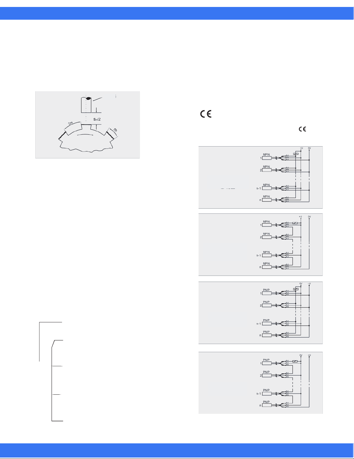
mark
Products in the list of products meet the European standard
EN 60947 - and EN 60947-5-22,so all have the mark .
Sensor series-parallel a chart
NPN Parallel
output
a chart
Shut off the time delay
Sensors to cut off the power supply of the moment to its
ready and shut off the normal signal interva
The response time
When the sensor switch to enter or leave the response time
of the action zone
Working environment temperature
Is to ensure reliable sensor working environment temperature
range
Protection grade
IP protection grade shall be formulated by the DIN 40050/IEC 60529
the following sensor is commonly used protection grade rules:
6 Completely avoid contact with the shell between
internal activity components,to prevent dust
intrusion protection
4 The waterproof splash, protection for water
splashing from any directionTest conditions for
1 bar pressure, 10 l/minutes plus or minus 5%
of the water spray for 5 minutes
IP 6 7
5 Water protection, under specific conditions, any
direction nozzle spray out of the water without
adverse effects Test conditions for 1 bar pressure
12.5 MM diameter nozzle distance is 3 meters
7 Flood protection, in a certain pressure and time
water shall not enter the shell.Test conditions,
to 1 m deep water for 30 minutes
NPN Serial
output
a chart
PNP Parallel
output
a chart
PNP Serial
output
a chart
8 Immersed in a specific pressure and time such
as water, water will not invade the damage to the
equipment. Test conditions for more than 5 meters
deep water for a month
I-SD-7

PARAMETERS FUNCTION
Functional description
The working principle of inductive proximity switch
Inductive proximity switch mainly is to use the metal conductor and
the mutual inductance alternating electromagnetic field theory, can make
the magnetic field will produce eddy current attenuation of metal materials.
This will make the magnetic field energy attenuation and decreasing
amplitude,in the inductive proximity switch such changes will make the
corresponding output level flip (as shown in the right 1)
Induction zone
Oscillation circuit
Inductive proximity switch standard induction
By induction type material for Fe37 steel to define the induction area,
its thickness to 1 mm.(according to EN 60947-5-2) dimension is take
induction flour for the side length of the square or for three times the
diameter circle detection distance (either the head).
The correction coefficient of inductive proximity switch
Relative to the standard test, the detection distance of the provisions
in the specified measurement conditions, tend to reduce the detection
distance,the smaller the correction factor, the action of a particular material
the smaller distance, the attenuation coefficient depending on the shell,
especially the shielding materials will be change. For inductive proximity switch,
the electrical conductivity of the test material is the main parameters affecting
the attenuation coefficient. The following data shows the induction of different
objects, the induction distance attenuation coefficient,
Such as right as shown in table 1.
Inductive proximity switch standard response curve (as shown in figure 2)
Trigger circuit
The output driver
Material:
Target Material
Fe37 steel 1
Aluminum 0.35-0.6
Yellow copper 0.4-0.7
Copper
Stainless steel
Cast iron 0.95-1
Nickel
Reduction Rate
0 . 8 - 1
(figure 1)
0.25-0.5
0.6-0.75
(table 1)
标准目标,轴向接近
Standard target, axial close
Standard target, radial approach Standard target, radial approach
标准目标,径向接近 标准目标,径向接近
1 0.8 0.6 0.4 0.2
1 0 . 8 0.6 0. 4 0 . 2
标 准目标, 轴 向 接近
Closing point
闭合点 断开点
闭合点
Diameter on the surface of the induction(D)
(mm)
1
1 1 1 1 1 1 1
0.6
0 . 6
0.4
0.4
0.2
0.2
0 0.2 0.4 0.8 0.6 1
0 0. 2 0 . 4 0 .8 0.6 1
(figure 2)
Disconnect point
(mm)
I-SD-8
 Loading...