

King Electrical LPW2445C, LPW2045C User Manual
INSTALLATION INSTRUCTIONS
SAVE THESE INSTRUCTIONS
LPW2045C 208 Volt and LPW2445C 240 Volt MODELS
Power must be brought to the heater first - then to wall thermostat
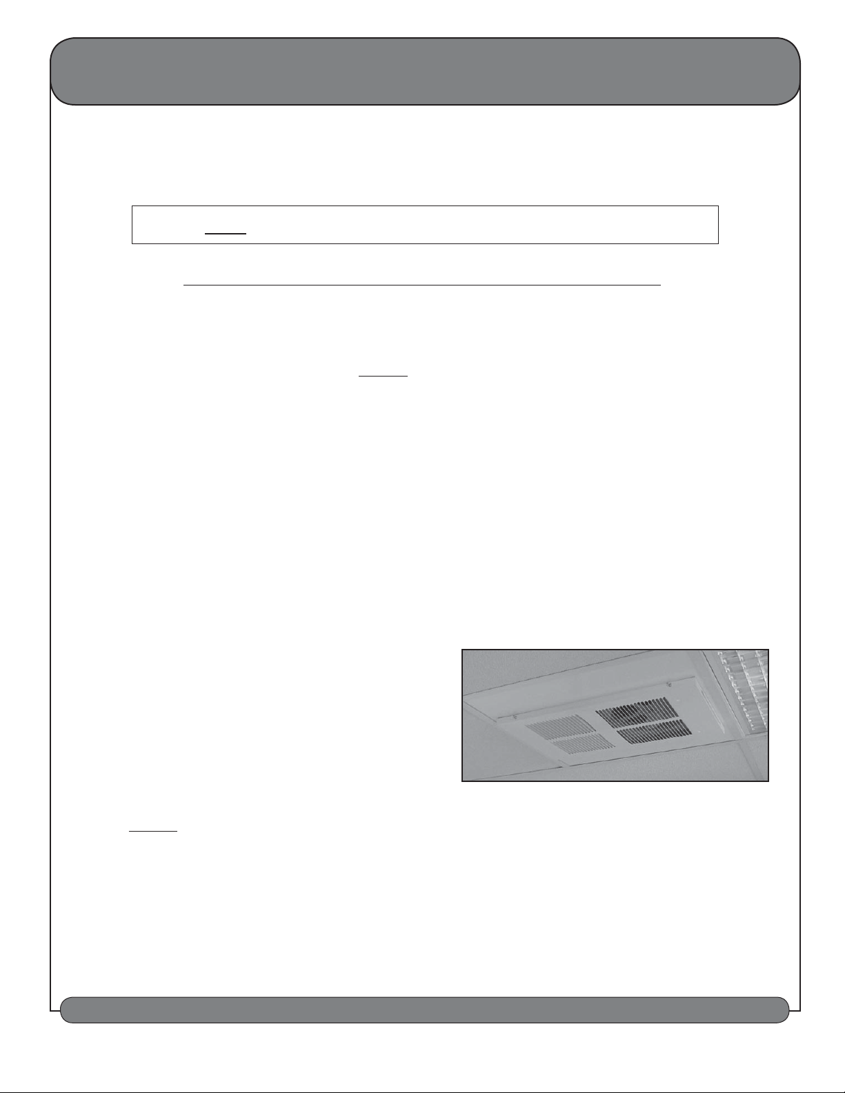
Instructions for ceiling mount unit with remote wall thermostat
It is extremely important to verify that the electrical power supply is the same voltage as the heater you are installing. 208 / 240 / 277 and 120 Volt
heaters are not interchangeable! Powering a 208 / 240 / 277 Volt unit with 120 Volt supply wires will reduce the heater's output by approximately 75%.
Powering a 120 Volt unit with 208 / 240 / 277 Volt supply wires will destroy the heater and voids all warranties.
NOTICE: The power must be brought to the heater first (not to the wall mounted or remote thermostat). This is necessary to provide power for the fan to
cool down the element after the thermostat has opened. Use a single pole line voltage wall thermostat or switch to control this heater.
CAUTION: Open the circuit breaker supplying the heater before attempting installation, maintenance, or repairs. Lock or tag circuit breaker
panel door. Failure to do so could result in serious electrical shock, burns, or possible death.
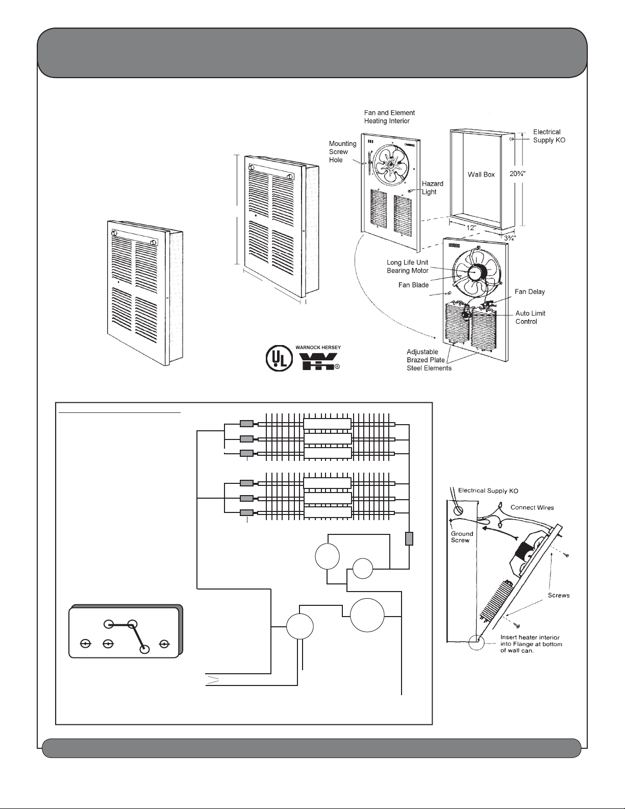
1. Remove heater contents from carton.
2. Remove grille by loosening the four mounting screws along the sides of the front panel.
3. Detach interior assembly from the ceiling case by removing the four screws along each side of the interior panel. Lift and tilt assembly away from the
top of the ceiling case. Free the bottom edge from the metal lip inside the ceiling case. Place the interior assembly in a safe location until the ceiling
case is mounted.
4. Mount heater enclosure can on ceiling joists a minimum of 6" from side wall, using the holes provided in the sides of the case. The face of the case
should be flush with the finished ceiling surface. Installation of the interior and grille to the ceiling case will cover an approximate 1/2" periphery along
the outer area of the opening.
5. Mount heater wall installation case on wall studs a minimum of 6" from side wall or open edge of a door and a minimum of 4" from floor (10" recom mended), using the holes provided in the sides of the case. The face of the case should be flush with the finished wall. Installation of the interior and
grille to the ceiling case covers an approximate 5/8" periphery along the outer area of the opening.
6. After ceiling case is secured, interior assembly leads may be attached to
supply wires and interior secured to ceiling case. NOTE: The LPW heater
is equipped with two steel elements having a capacity of 2250 Watts each,
for a combined capacity of 4500 Watts. The heater is factory-wired at 4500
Watts. To adjust the heater for lower wattages remove the appropriate
colored wire according to the illustration and wattage diagram provided on
the back side of this sheet. Be sure to insulate and secure the unused lead.
7. Reinstall interior assembly on ceiling case using screws provided.
8. Mount grille to interior with screws provided.
9. Installation is now complete and the heater ready for use.
10. Use a single pole line voltage wall thermostat or switch only to control this heater.
Maintenance & Warranty
The high quality and superior design of this unit will enable years of maintenance-free performance. Once yearly the heater should be
checked for lint or dust accumulation but no further maintenance is required. The motor is permanently lubricated and sealed. A five year
warranty is provided on the Pic-A-Watt element and 1 year on all materials, components and workmanship.
OWNERS GUIDE & INSTALLATION INSTRUCTIONS SHOULD BE LEFT WITH HEATER FOR HOME OWNER
KING ELECTRICAL MFG. COMPANY • 9131-10th Ave South • Seattle, WA 98108 • Phone (206) 762-0400 • Fax (206) 763-7738 • www.king-electric.com
INSTALLATION INSTRUCTIONS
SAFETY LIGHT
NOTICE - The light may illuminate periodically during normal
operation for 10 to 45 seconds.
This flashing is not a hazard. If
the light stays on steadily for 1 to
5 minutes an over-temperature
condition probably exists and the
heater should be examined.
SAVE THESE INSTRUCTIONS
21¾"
13"
Safety Light
½"
INSTALLATION INSTRUCTIONS
This heater is shipped from the factory
wired for maximum wattage of 4500
Watts. To reduce the wattage unplug
(disconnect) an insulated push on
terminal and wrap with electrical tape
to prevent the possibility of electrical
contact with other parts.
WIRE COLOR CODING
A - Orange - disconnects the
1000 Watt element
B - Blue - disconnects the
750 Watt element
C - Yellow - disconnects the
500 Watt element
D - Black - Energized Common Leg
Do Not Disconnect
RED
BLUE
YELLOW
Insulated Push on
ORANGE
RED
RED
Insulated Push on
RED # 14 GAUGE
E
B
C
Terminal
A
E
E
Terminal
1000 WATT
750 WATT
500 WATT
1000 WATT
750 WATT
500 WATT
HAZARD
LIGHT
LIMIT
BLACK
D
BLACK
This heater includes a visual alarm to
warn that parts of the heater are getting
excessively hot. If the alarm flashes,
immediately turn the heater off and inspect
for any objects on or adjacent to the heater
that may cause high temperatures.
E - Red - Do Not Disconnect
D
Common
AC
B
1000
750
END VIEW OF ELEMENT
SHOWING QUICK CONNECT TERMINALS
A - 1000 WATT B - 750 WATT C - 500 WATT
D - COMMON LEG OF POWER SUPPLY
2250 - 2750 - 3000 - 3250 - 3750 - 4000 - 4500
WATTAGES AVAILABLE IN ONE UNIT
500
Pic-A-Watt
Metal Sheath Element
ORANGE Wall Thermostat Leads
®
1
FAN
3
DELAY
2
BLACK
LINE 1
MOTOR
RED
#14 GAUGE
LPW2045C
LINE 2
LPW2445C
LPW 2045C-2445C.indd : 9/09
OWNERS GUIDE & INSTALLATION INSTRUCTIONS SHOULD BE LEFT WITH HEATER FOR HOME OWNER
KING ELECTRICAL MFG. COMPANY • 9131-10th Ave South • Seattle, WA 98108 • Phone (206) 762-0400 • Fax (206) 763-7738 • www.king-electric.com
 Loading...