

King-Dome Trac-King In-Motion 9760, Trac-King In-Motion 9762 Installation And Operating Instruction
Trac-King In-Motion Satellite System
#9760/9762
Installation and Operating Instructions
11200 Hampshire Avenue South, Bloomington, MN 55438-2453
Phone: 800-982-9920 Fax: 952-922-8424
www.kingcontrols.com
1355 REV C
Satellite Solutions for Mobile Markets
KKIINNGG
CCOONNTTRROOLLSS
Trac-King
®
Page 1
IMPORTANT!
The satellite TV market is expanding and changing. The information in this manual was
accurate at the time of printing. If your King-Dome does not operate as outlined in this
manual please call King Controls at 1-800-982-9920 or visit our website at
www.kingcontrols.com.
TABLE OF CONTENTS
Section Contents Page
1. INTRODUCTION.....................................................................................2
2. DEFINITION OF TERMS ........................................................................3
3. INSTALLATION..................................................................................4-13
4. OPERATION ....................................................................................14-17
5. TROUBLESHOOTING.....................................................................18-19
6. MAINTENANCE ....................................................................................20
7. LIMITED WARRANTY ..........................................................................21
DIRECTV®is an official trademark of DIRECTV, division of GM Hughes Electronics Corporation.
Dish Network®is an official trademark of Echostar Communications Corporation.
Bell ExpressVu
®
is an official trademark of Bell Canada.
DVB®is a trademark of the DVB Digital Video Broadcast Project (1991-1996)
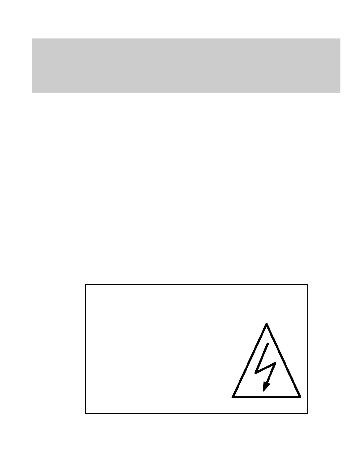
ELECTRICAL HAZARD WARNING!
The coaxial cable that connects the dome
unit to the tuner carries a 30 volt electrical
current. Exercise extreme caution when
handling this cable. Do not cut, break, or
splice this line. Do not insert or connect
any devices such as splitters or any other
device for any reason. This line is not
compatible with any other equipment.
Damage will occur to any device other than
the dome unit if connected to the antenna
port on the tuner.
Page 2
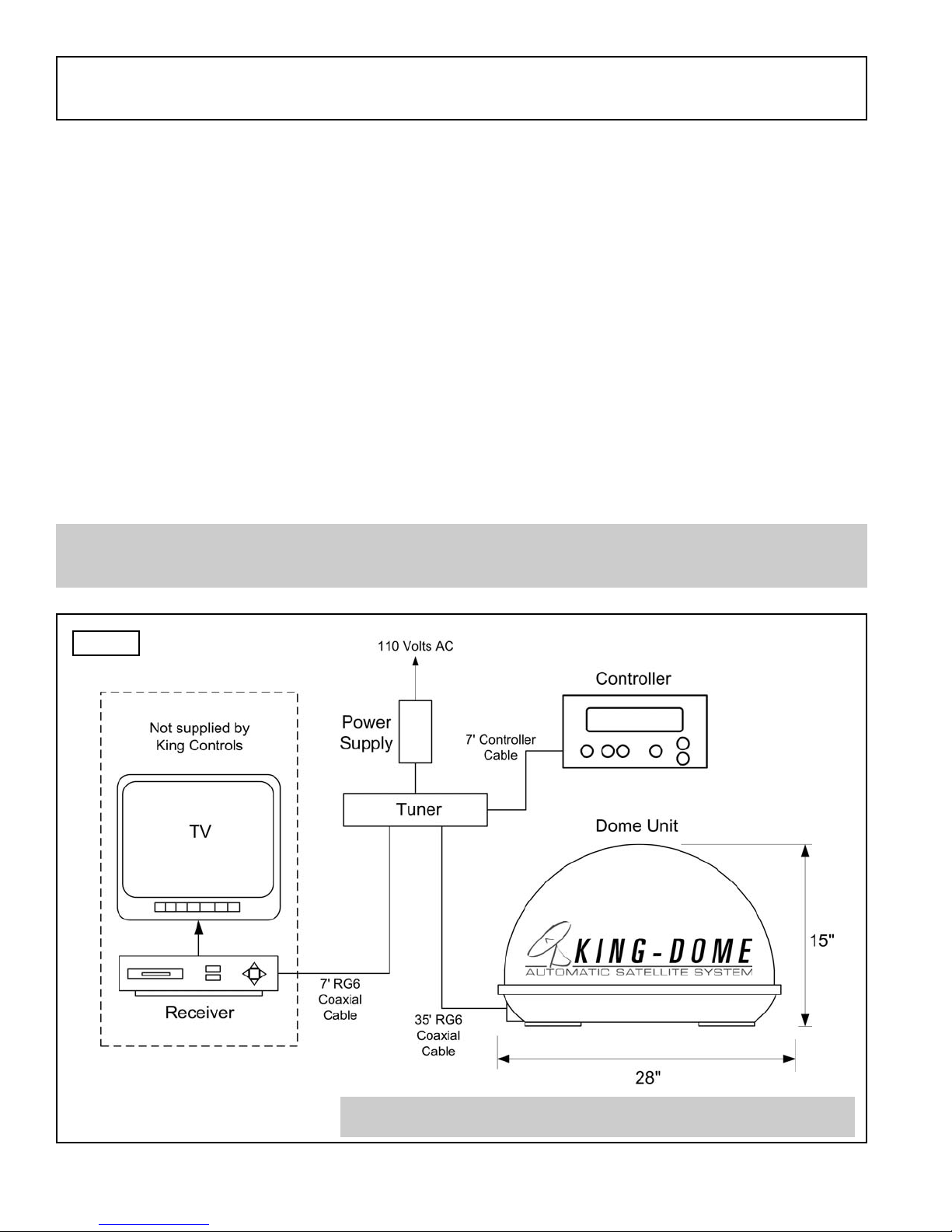
The Trac-King In-Motion Satellite System includes 4 main components. (Fig. 1)
Dome (Antenna) Unit Located on the roof of the vehicle. The dish is covered by a
protective dome that keeps operational components free from
the elements.
Controller Located in the vehicle. Used to activate and monitor the
system, and access programming and diagnostic information.
Tuner Located in the vehicle. Decodes the satellite signal so the
Trac-King locks onto the correct satellite.
Power Supply Located in the vehicle. Supplies proper operating voltage to
the Trac-King.
SECTION 1
INTRODUCTION
Note: A TV, satellite receiver, and program subscription are also required for satellite TV
viewing. (Not supplied by King Controls.)
Fig. 1
Note: For 9762 Dual In-Motion system see Pages 12-13.
KING-DOME
Trac-King
START/STOP DISPLAYSELECT
MODIFY
Page 3
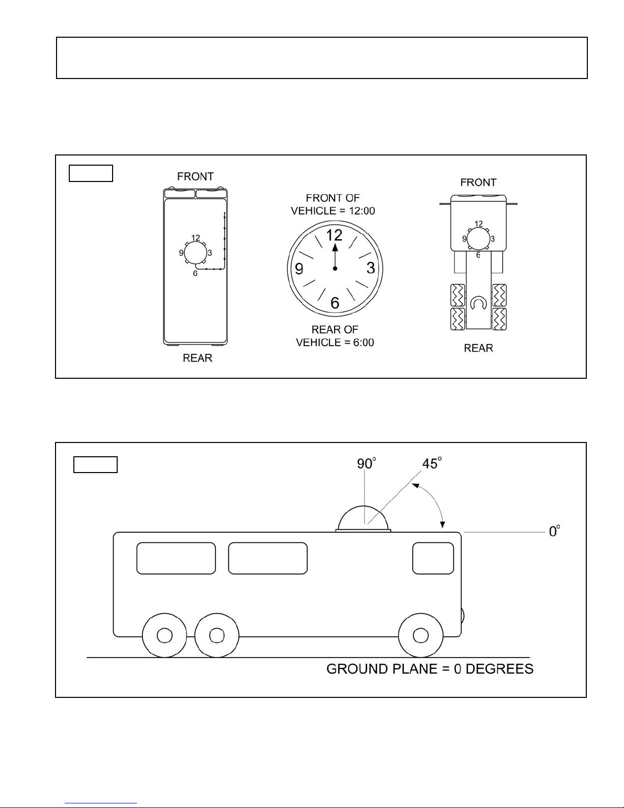
AZIMUTH: Circular rotation around the vehicle.
(like a clock face: front of vehicle is 12:00, rear is 6:00) (Fig. 2)
SIGNAL STRENGTH: Intensity of electronic signal received from the satellite transmission.
SECTION 2
DEFINITION OF TERMS
Fig. 2
Fig. 3
ELEVATION: Angle in degrees measured from the ground plane. (Fig. 3)

Page 4
SECTION 3
INSTALLATION
TOOLS AND MATERIALS REQUIRED:
- drill and drill bit set
- tape measure
- 7/16” open end wrench (coax connections)
- adhesive sealant (compatible with roof material)
- appropriate fasteners to install all components and wiring
- 5/32” allen wrench, channel lock or pliers (to remove shipping bolt)
- wire cutter (to remove shipping tie strap)
KIT CONTENTS:
1. Unpack and identify all components. (Fig. 4)
KING DOME
QUICK REFERENCE CARD
The Trac King has a variety of
options, settings, and information
availabe via its display module.
Please review your owner’s
manual for a more detailed
explanation. the display module is
used to provide the system current
status and set your region, and
select your satellite.
Fig. 4
Page 5
Fig. 5
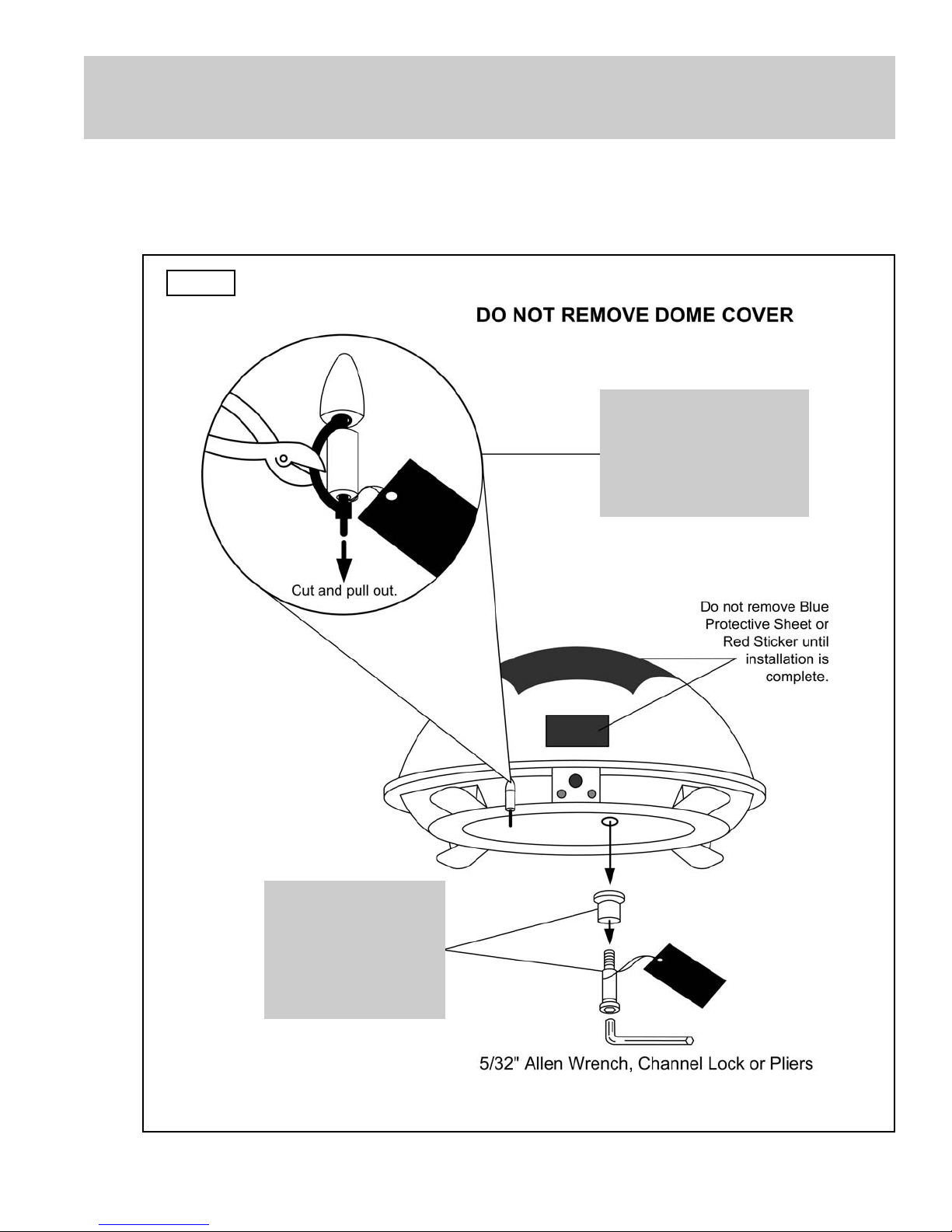
IMPORTANT! The tie strap, bolt and plastic spacers must be removed from the bottom
of the dome unit prior to installation. DO NOT REMOVE THE DOME
COVER TO REMOVE THESE SHIPPING RESTRAINTS.
2. Remove and discard the tie strap, bolt and plastic spacers that pass through the bottom
of the base. (Fig. 5)
IMPORTANT!
Remove and
discard Bolt and
Plastic Spacer prior
to installation.
IMPORTANT!
Remove and discard
Tie Strap and Plastic
Spacer prior to
installation.

Page 6
DOME LOCATION
3. Select an area on the roof for the dome unit and the location where the wiring will enter
the vehicle through the roof to the satellite receiver and internal components, using the
following criteria:
a) The shortest distance between the dome unit and the satellite receiver is most
desirable.
a) The dome unit requires a 28 inch diameter circle.
b) The dome unit should be mounted on the centerline of the vehicle (side to side).
c) There must be no “line of sight” obstructions from this location. Air conditioning
units, other antennas, and storage areas that are too close to the dome unit may
prevent the satellite signal from reaching the dish. (Fig. 6)
HEIGHT OF
OBSTRUCTION
APPROXIMATE
MINIMUM DISTANCE
TO DOME EDGE
10” 8”
11” 10”
12” 12”
13” 14”
14” 16”
15” 18”
16” 20”
Fig.6
IMPORTANT! For installations on trucks with air shields, a bracket must be used for
mounting the dome unit. The dome unit MUST be mounted to the air ride
cab: NEVER to any structure mounted directly to the frame.
See bracket instructions for proper installation. (Fig. 7)
 Loading...