

Automatic Satellite System
for DISH® Programming
Model KD5500
Installation and Operating Instructions
®
11200 Hampshire Avenue South, Bloomington, MN 55438-2453
Phone: (952) 922-6889 Fax: (952) 922-8424
21507 REV A
Digital TV Solutions for Mobile Markets
www.kingcontrols.com


IMPORTANT!
The Relay Automatic Satellite System is designed to work with both standard defi nition and high defi nition
satellite TV broadcasts from DISH satellites 110/119/129, and ONLY with DISH model ViP211z, ViP211k, ViP211
and 411 receivers. It will not work with other DISH receiver models or with equipment for other satellite TV
service providers.
The mobile satellite TV market is expanding and changing. The information in this manual was accurate at the
time of printing. If your Relay antenna does not operate as outlined in this manual, please call King Controls
at (952) 922-6889 or visit our website at www.kingcontrols.com. King Controls is not responsible for changes
outside of its control.
Please read this entire manual before beginning the installation process.
TABLE OF CONTENTS
Section Contents Page
1. INTRODUCTION . . . . . . . . . . . . . . . . . . . . . . . . . . . . . . . . . . . . . . . . . . . . . . . . . . . . . . . .2
2. WIRING DIAGRAM . . . . . . . . . . . . . . . . . . . . . . . . . . . . . . . . . . . . . . . . . . . . . . . . . . . . . .3
3. INSTALLATION . . . . . . . . . . . . . . . . . . . . . . . . . . . . . . . . . . . . . . . . . . . . . . . . . . . . . . . 4-7
4. OPERATION. . . . . . . . . . . . . . . . . . . . . . . . . . . . . . . . . . . . . . . . . . . . . . . . . . . . . . . . . 8-16
5. SECOND RECEIVER OPERATION. . . . . . . . . . . . . . . . . . . . . . . . . . . . . . . . . . . . . . 18-19
6. TROUBLESHOOTING . . . . . . . . . . . . . . . . . . . . . . . . . . . . . . . . . . . . . . . . . . . . . . . . 20-23
7. MAINTENANCE . . . . . . . . . . . . . . . . . . . . . . . . . . . . . . . . . . . . . . . . . . . . . . . . . . . . . . . . 24
8. LIMITED WARRANTY . . . . . . . . . . . . . . . . . . . . . . . . . . . . . . . . . . . . . . . . . . . . . . . . . . .25
DISH is a registered trademark of DISH Network L.L.C.
Relay is a trademark of Electronic Controlled Systems, Inc. DBA King Controls.
King Controls and King-Dome are registered trademarks of Electronic Controlled Systems, Inc. DBA King Controls.
Page 1
Section 1 INTRODUCTION
The Relay model KD5500 Automatic Satellite System is designed for permanent, roof mounted
installation on a recreational vehicle. A single coax cable connection between the Relay antenna
and your DISH model ViP211z, ViP211k, ViP211 or 411 receiver provides power to the automated
positioning system under the dome and transmits your SD and HD satellite video signals to your
receiver.
An optional second receiver may be connected to provide independent channel viewing on a second
TV. Your DISH programming is broadcast from two or three satellites and the Relay antenna
automatically switches between satellites based on the channel selected on your main receiver.
Channels available on the second receiver will depend on the channel (satellite) selected on the
main receiver.
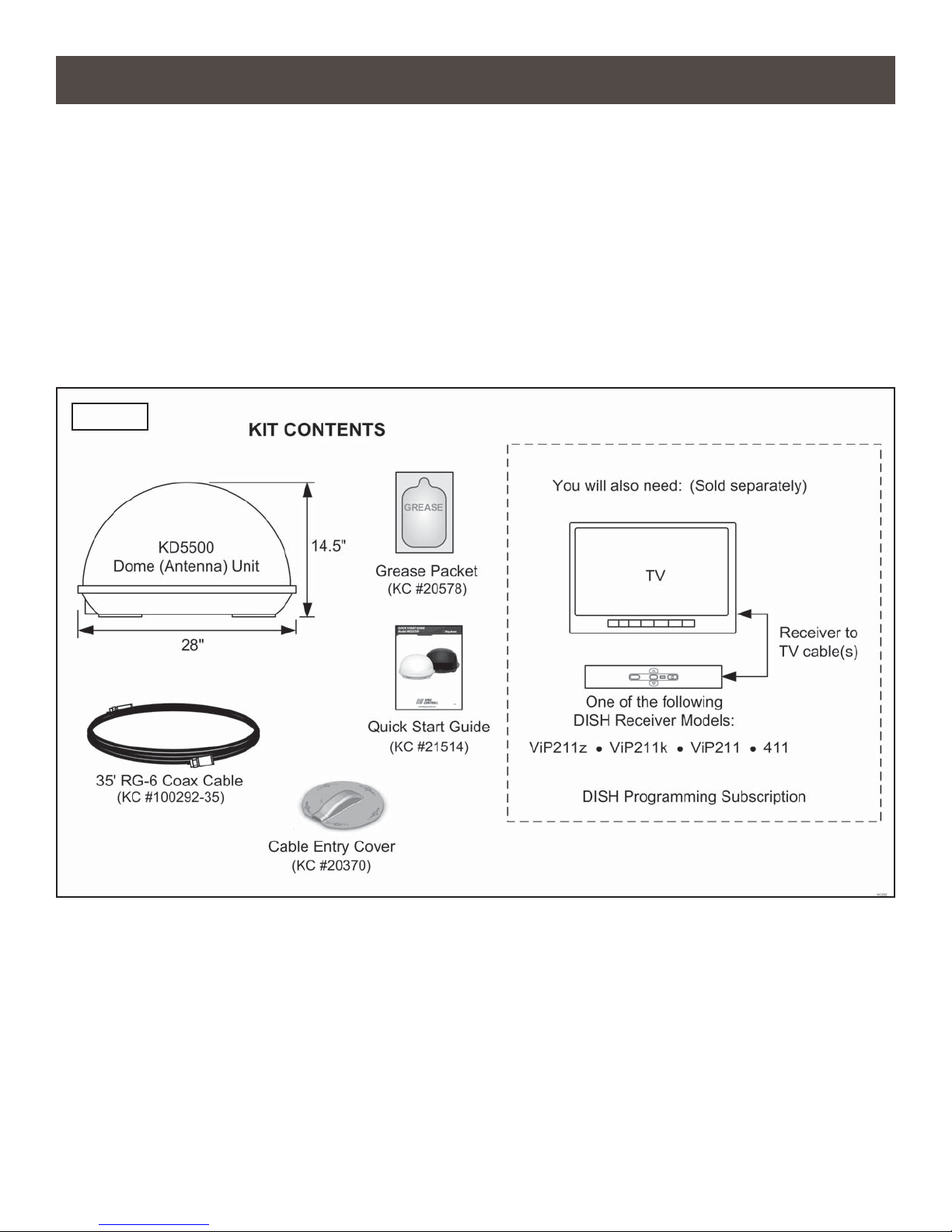
FIG. 1
TOOLS AND MATERIALS REQUIRED
• drill and drill bit set
• tape measure
• 7/16” open end wrench (coax connections)
• adhesive sealant (compatible with roof material)
• appropriate fasteners to install all components and wiring
Page 2
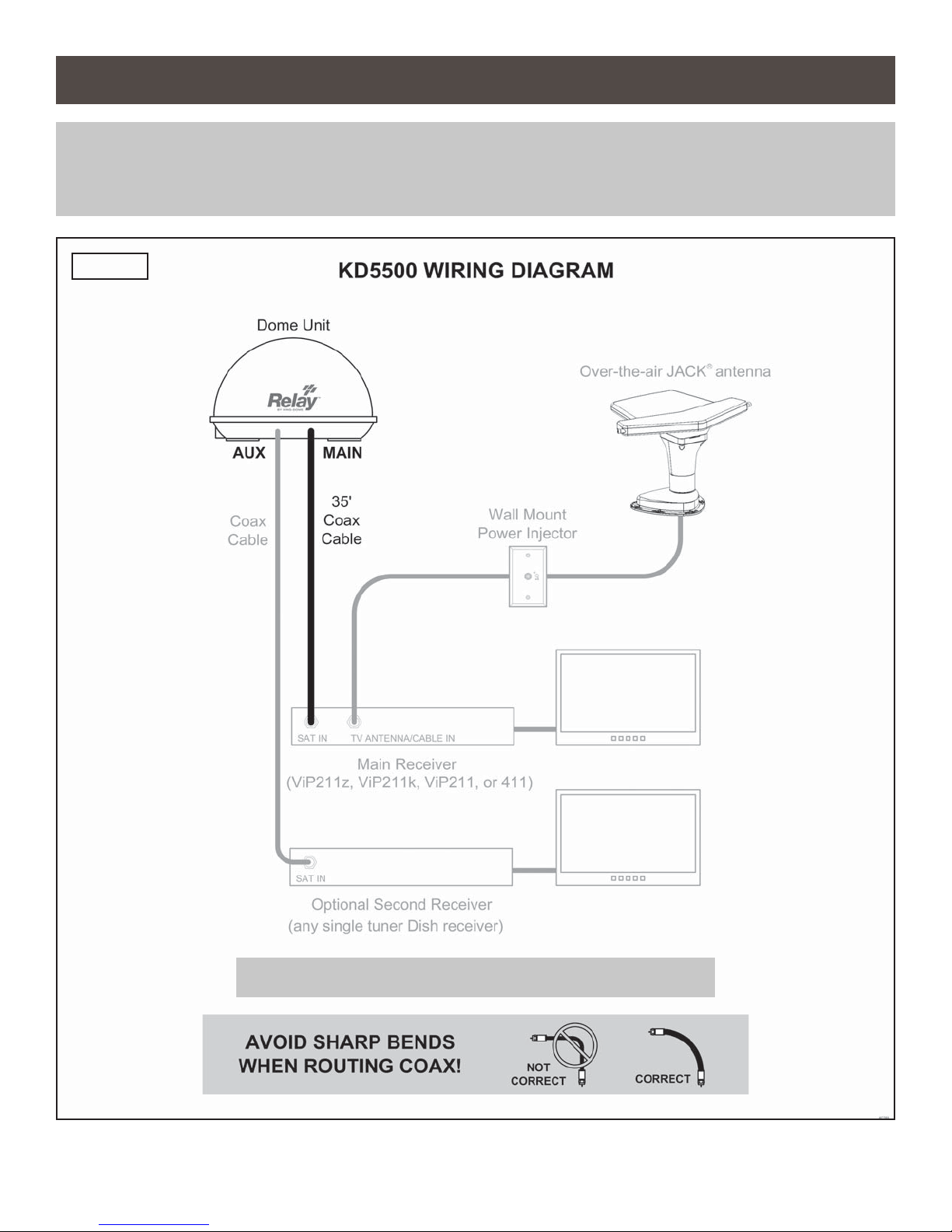
Section 2 WIRING DIAGRAM
NOTE: All components sold separately except for dome unit and main 35 foot coax.
See your respective owner’s manuals for the best connections between your compatible DISH receiver and TV.
FIG. 2
IMPORTANT! DO NOT OVER TIGHTEN COAX CONNECTIONS.
Page 3
Section 3 INSTALLATION
NOTE: Many RVs are pre-wired for satellite with RG-6 coax cable. Contact the manufacturer of your RV or your local
dealer to verify where this cable is located.
If pre-wired, run the existing coax cable from the pre-wire location in the roof to the dome unit. When choosing
the dome unit location, make sure the pre-wiring will reach the dome unit.
Make all connections, properly route and fasten wiring to roof, and completely waterproof entry hole with the
cable entry cover as shown in this section. You may still run a second coax to the rear of the vehicle for an
optional second receiver.
DOME UNIT LOCATION
1. Select an area on the roof for the dome unit and the location where the wiring will enter the
vehicle through the roof to the satellite receiver inside using the following criteria:
a) A shorter distance between the dome unit and the satellite receiver is most desirable.
b) The dome unit requires a 28 inch diameter mounting area.
c) The dome unit should be mounted on the centerline of the vehicle.
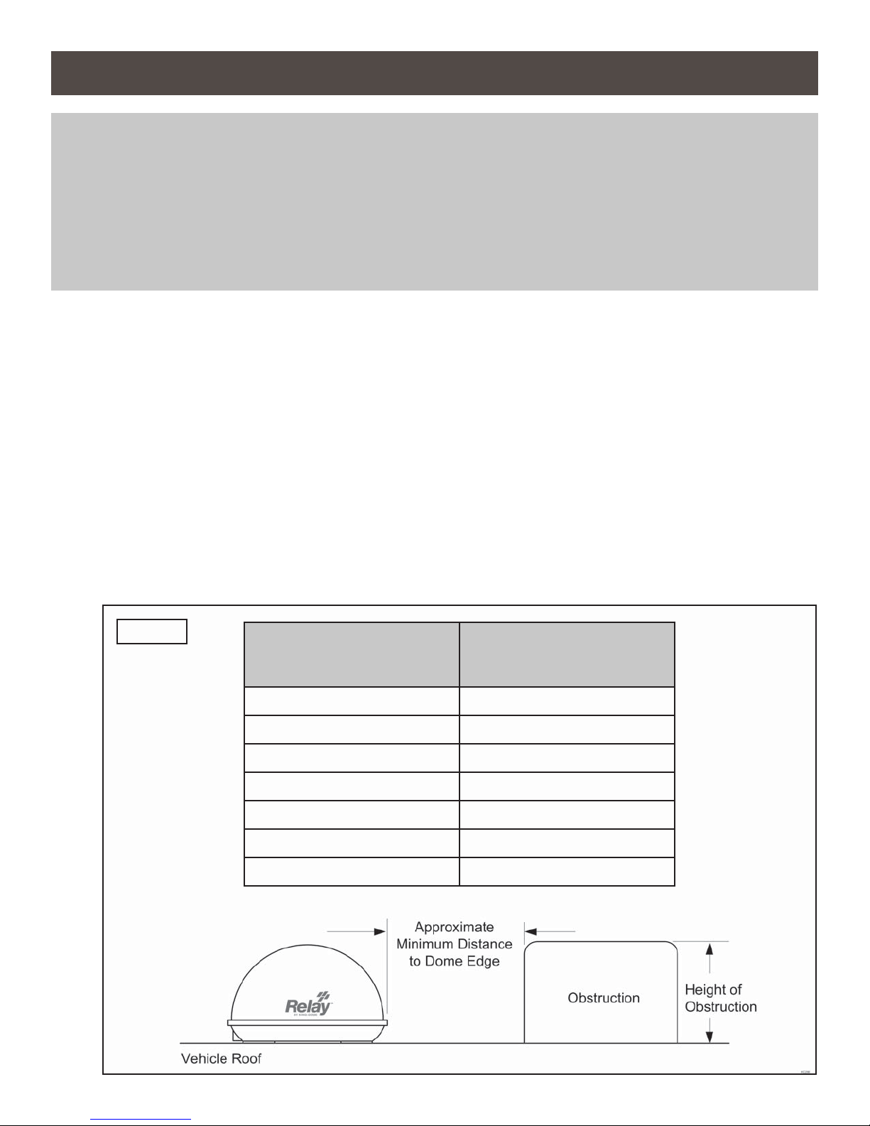
d) There must be no “line of sight” obstructions. Air conditioning units, other antennas, and
storage areas that are too close to the dome unit may prevent the satellite signal from
reaching the antenna (Fig. 3).
FIG. 3
HEIGHT OF
OBSTRUCTION
APPROXIMATE
MINIMUM DISTANCE
TO DOME EDGE
10” 8”
11” 10”
12” 12”
13” 14”
14” 16”
15” 18”
16” 20”
Page 4
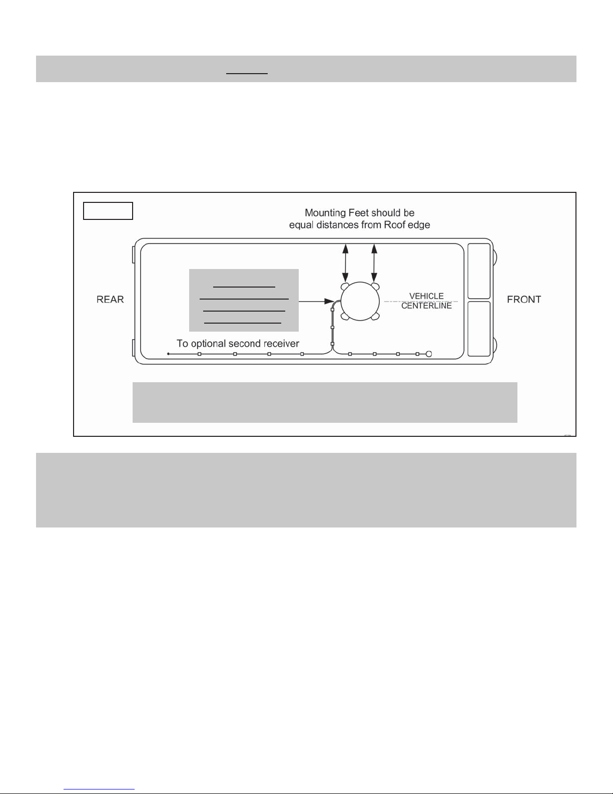
DOME UNIT INSTALLATION
IMPORTANT! Cable connections must ALWAYS be positioned facing the rear of vehicle.
2. Place dome unit on installation location chosen using the criteria discussed in the previous
section. Cable connections must be positioned facing rear of vehicle.
3. The dome unit must be positioned so that both mounting feet on each side of the vehicle are
equal distances from the roof edge. This should be checked by measuring the distance from
each foot to the roof edge. Confi rm that these measurements are equal (Fig. 4).
FIG. 4
IMPORTANT!
Cable connections
must always face
REAR of vehicle.
IMPORTANT! The dome unit should never be mounted so that it is tilted more
than two degrees in any direction.
NOTE: The installer is responsible for determining the most appropriate fasteners to secure the dome unit to the roof.
Depending on the roof material, fasteners such as lag screws, well nuts, sheet metal screws, toggle bolts and T
anchors may be used, and should always be used in combination with a roof compatible sealant.
IMPORTANT! The installer is responsible for weatherproofi ng all holes with sealant.
4. Mount the dome unit. Use the pre-drilled holes in the mounting feet as a guide to install the
fasteners into the roof. Use additional fasteners whenever necessary.
5. Test that the dome unit is secure by pulling upward from each foot location.
Page 5
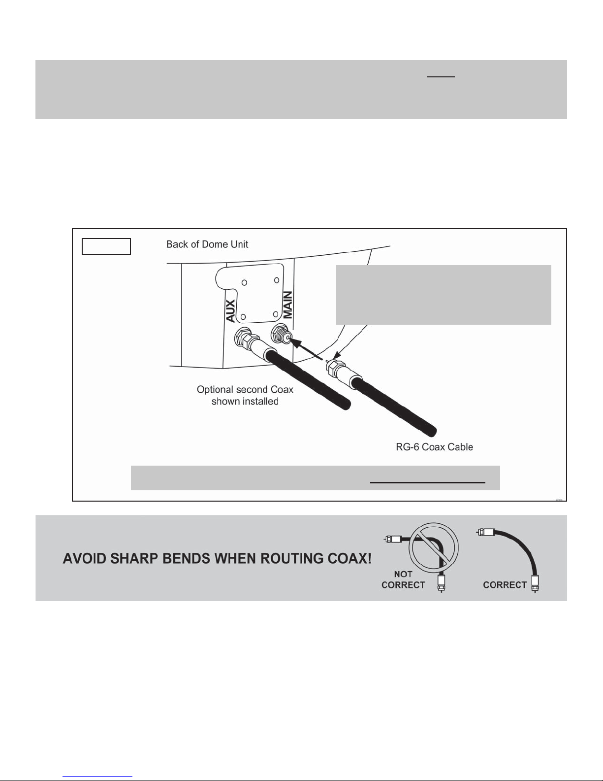
EXTERNAL WIRING
NOTE: There are two coax ports on the back of the dome unit. The one labeled “MAIN” MUST be connected to the
main receiver in vehicle (DISH model ViP211z, ViP211k, ViP211, or 411 only). This is the receiver that will
control automatic satellite switching. The one labeled “AUX” can be used for an additional receiver (may be
any single tuner DISH receiver - see Section 5 of this manual).
6. Fill end of coax cable that will connect to the MAIN port on the dome unit with supplied
dielectric grease. Connect this end of the coax cable to the MAIN port and tighten connection
(Fig. 5). DO NOT OVER TIGHTEN.
If using a second receiver, fi ll end of second coax cable with supplied dielectric grease and
connect it to the AUX port. Tighten connection. DO NOT OVER TIGHTEN.
FIG. 5
IMPORTANT!
FILL ENDS OF BOTH EXTERNAL
COAX CABLES WITH GREASE.
Failure to do so will void product warranty.
IMPORTANT! Coax connections should be snug. DO NOT OVER TIGHTEN!
7. Run the main coax from the back of the dome unit to the roof edge, then along the edge to
the location where it will be fed into the vehicle. If installing an optional second receiver, run
second coax to location where it will enter the vehicle. Secure wiring to roof every 12-18
inches (Fig. 6).
Page 6
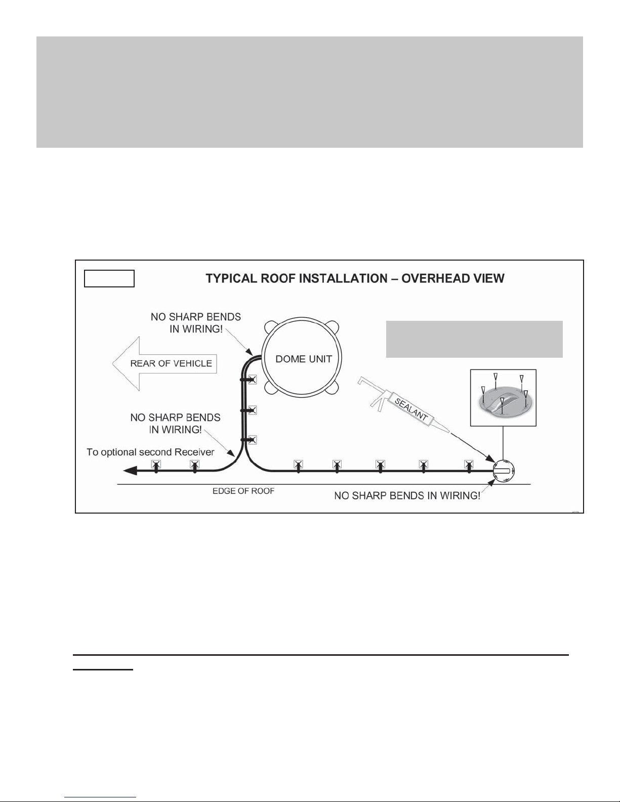
IMPORTANT! Use adhesive sealant compatible with roof material.
Installer is responsible for determining proper roof compatible adhesive sealant and
fasteners for cable entry cover.
Roof holes for cables must be sealed so they are completely waterproof. Mounting holes,
perimeter of cable entry cover and cable opening of cable entry cover must be sealed so they
are completely waterproof.
8. Drill 3/4” hole through the roof and into the cabinet where receiver is stored. Feed coax down
through hole. Seal opening with roof compatible sealant so that it is completely waterproof
(inside and outside of the 3/4” hole). Repeat for second coax if present.
9. Fasten cable entry cover to roof with appropriate adhesive sealant and roof fasteners. Seal
mounting holes, perimeter of cover and cable opening so they are completely waterproof.
FIG. 6
IMPORTANT!
Sealant must be roof compatible.
10. Remove blue protective sheet and red “position to rear” sticker from the dome unit.
INTERNAL WIRING (FIG. 2, PAGE 3)
11. Connect the coax from the MAIN port on the dome unit to SATELLITE IN on your main receiver
(must be DISH model ViP211z, ViP211k ViP211 or 411).
DO NOT CONNECT THE COAX FROM THE AUX PORT TO THE SECOND RECEIVER AT
THIS TIME.
12. Go to OPERATION on page 8.
Page 7
Section 4 OPERATION
IMPORTANT: IF YOUR RECEIVER IS NEW AND NOT YET ACTIVATED, YOU MUST PERFORM THE FIRST TIME
SETUP ON PAGE 12 BEFORE USING THE INSTRUCTIONS ON THIS PAGE.
THIS ANTENNA IS DESIGNED TO WORK AUTOMATICALLY WITH DISH MODEL ViP211z, ViP211k,
ViP211 AND 411 RECEIVERS AND WILL NOT WORK WITH OTHER DISH RECEIVER MODELS OR
WITH EQUIPMENT FOR OTHER SATELLITE TV SERVICE PROVIDERS.
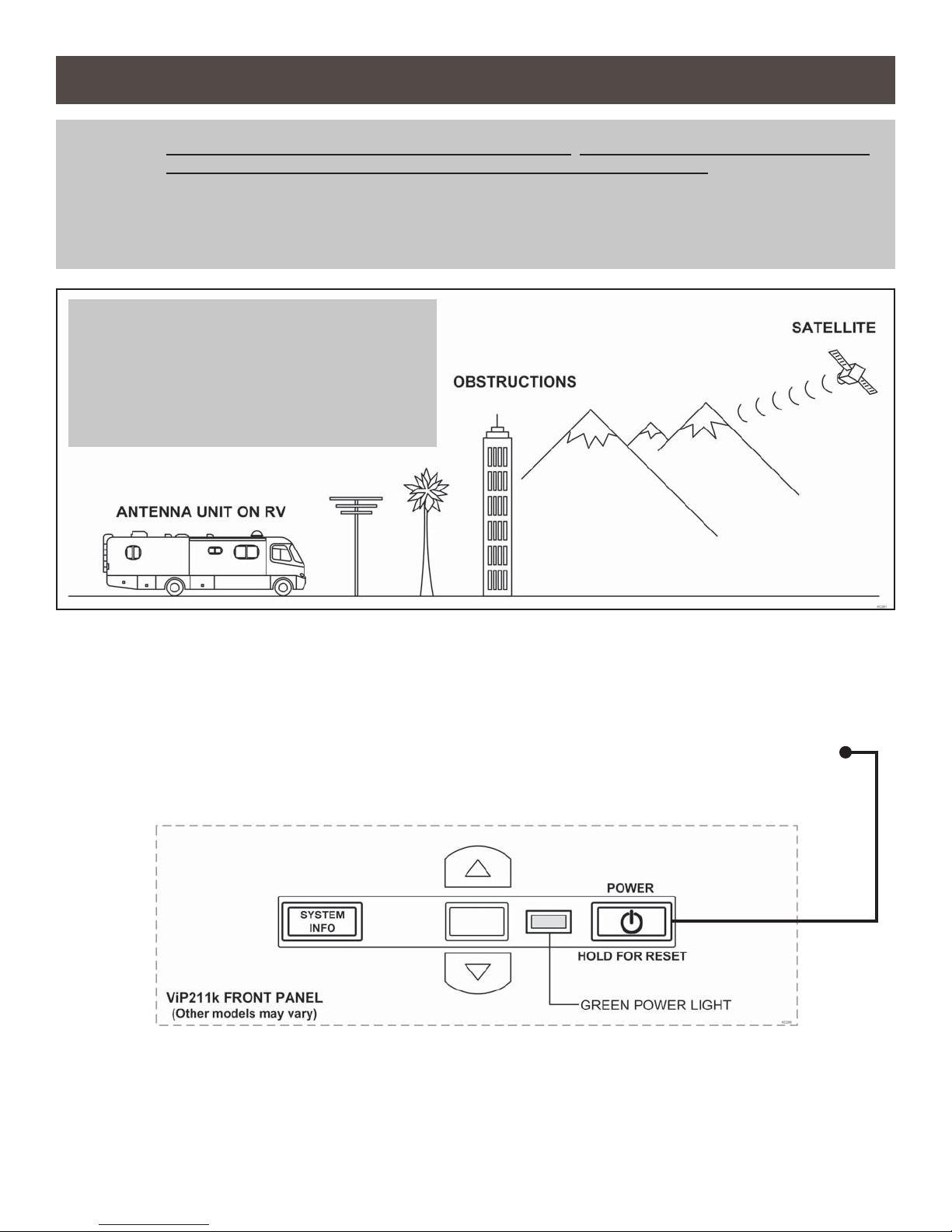
IMPORTANT!
The antenna unit requires a “direct line of
sight” to the satellites for signal reception.
Any tall objects such as poles, trees,
buildings, mountains, etc. can all block the
signal from reaching the dish.
1. Plug your receiver and TV into a 110 volt AC power source.
The green light on your receiver should illuminate or begin cycling on and off. Wait for the
green light to turn solid (this may take up to two minutes).
If the green light does not illuminate after two minutes, power on your receiver using the
front panel power button.
2. Turn on your TV.
Use your TV’s input selection menu to select the input that matches the connection to your
DISH receiver, i. e. if using an HDMI cable connection you should select the HDMI TV input.
Page 8

The Portable Antenna Setup screen will be displayed on your TV.
NOTE: If the Portable Antenna Setup screen does
not display, press MENU, 6, 1, 1 on your
DISH remote.
Highlight “Check Switch.”
Press SELECT on your remote.
The Portable Antenna Setup screen
should now display.
3. Use the arrow buttons on your
DISH remote to highlight the letter
group that includes the fi rst letter
of the state you are currently in.
Press SELECT on your remote.
4. Highlight the state you are currently
in from the state menu.
Press SELECT on your remote.
Page 9
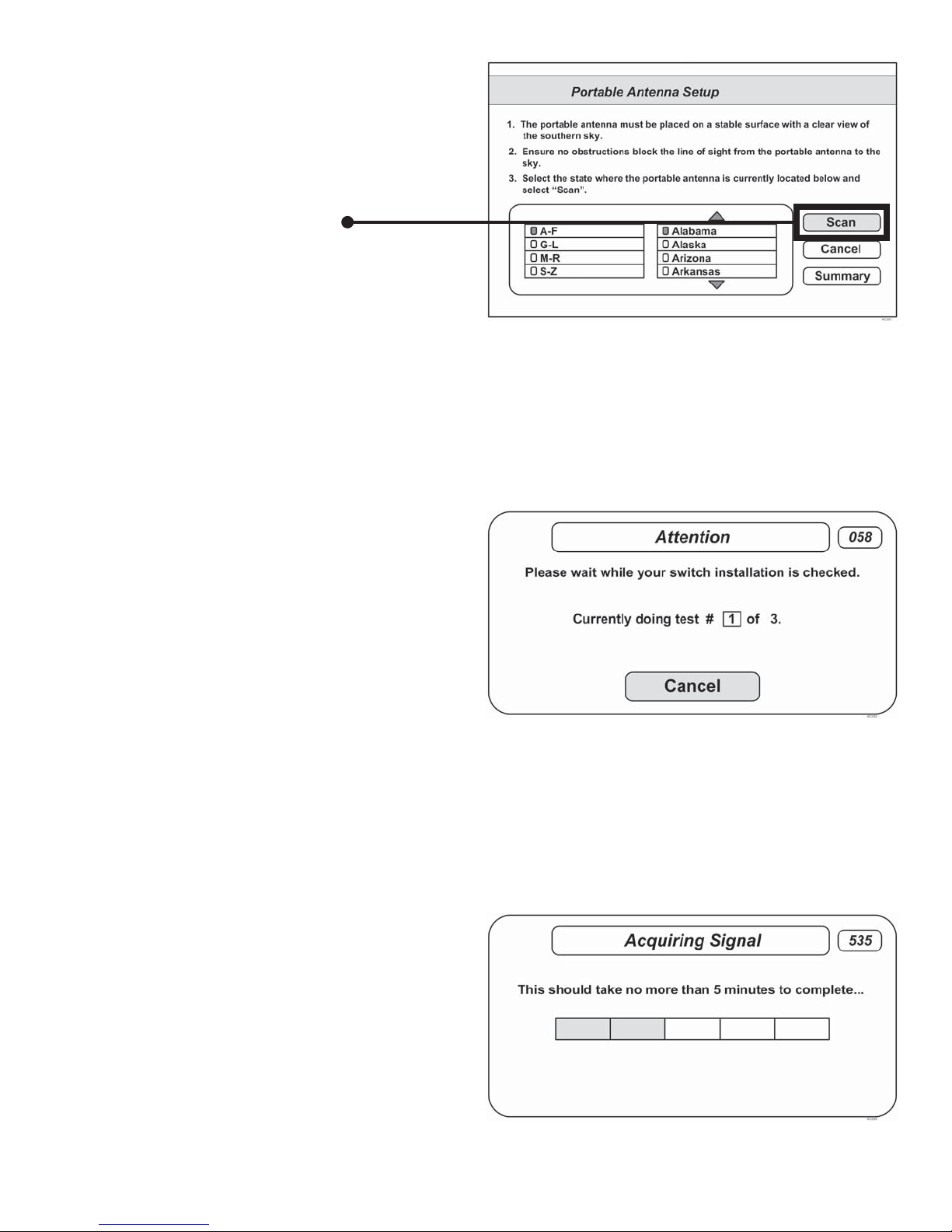
5. Verify “Scan” is highlighted.
Press SELECT on your remote.
The scan will begin and may take
several minutes to complete.
This screen will display during the scan:
6. When the scan is complete, the
Acquiring Signal message will display.
Acquiring the signal may take up to 5
minutes to complete.
Page 10

7. After your receiver has acquired the
signal, the electronic program guide
will download.
This may take up to 5 minutes to
complete (potentially longer if an
external hard drive is connected for
DVR use).
If you are using a second receiver, see SECOND RECEIVER OPERATION on page 18.
OPERATING NOTES
If your system is inactive for an extended period of time, you may need to call DISH Customer Service at
1-800-333-DISH (3474) to re-authorize your receiver. You can view your programming when your receiver has been
re-authorized and the guide has fi nished downloading.
If you move your vehicle, you will need to repeat the scan process to re-acquire the satellites and restore
programming.
When in the northeastern United States, television programming from the 129 satellite may not be available.
Page 11

INITIAL SETUP WITH NEW (UN-ACTIVATED) RECEIVER
IMPORTANT: If you have a NEW, not yet activated DISH receiver model ViP211z, ViP211k, ViP211 or 411, use
the instructions on this page for fi rst time setup. After this one time setup procedure, you can
use OPERATION on page 8.
THIS ANTENNA IS DESIGNED TO WORK AUTOMATICALLY WITH DISH MODEL ViP211z, ViP211k,
ViP211 AND 411 RECEIVERS AND WILL NOT WORK WITH OTHER DISH RECEIVER MODELS OR
WITH EQUIPMENT FOR OTHER SATELLITE TV SERVICE PROVIDERS.
IMPORTANT!
The antenna unit requires a “direct line of
sight” to the satellites for signal reception.
Any tall objects such as poles, trees,
buildings, mountains, etc. can all block the
signal from reaching the dish.
1. Point your receiver’s remote at the
front of the receiver and press SAT.
Press RECORD.
When a number appears in the box,
verify “Continue” is highlighted.
Press SELECT on your remote.
Page 12

The Portable Antenna Setup screen
will display.
2. Use the arrow buttons on your
remote to highlight the letter group
that includes the fi rst letter of the
state you are currently in.
Press SELECT on your remote.
3. Highlight the state you are currently
in from the state menu.
Press SELECT on your remote.
4. Verify “Scan” is highlighted.
Press SELECT on your remote.
Page 13

The scan will begin and may take up to
several minutes to complete.
This screen will display during the scan.
The receiver will download current
software.
The receiver will update with the
current software.
5. The receiver will reset and the
Portable Antenna Setup Screen will appear.
Choose your location again and
initiate a second scan.
Page 14

The antenna will scan a second time.
When the scan is complete, the
Acquiring Signal message will display.
Acquiring the signal may take up to 5
minutes to complete.
After your receiver has acquired the signal,
the electronic program guide will download.
This may take up to 5 minutes to complete
(potentially longer if an external hard drive
is connected).
6. The Set Video Resolution screen will
appear. Select the highest resolution
your TV will display.
Verify “Test” is highlighted.
Press SELECT on your remote.
Page 15

7. Verify “Save” is highlighted.
Press SELECT on your remote.
8. While this screen is displayed you may
be prompted with a “Continue” message.
If prompted, verify “Continue” is
highlighted and press SELECT
on your remote.
9. Call DISH to activate your new receiver.
1-800-333-DISH (3474)
This completes the initial setup for new receivers. You may now use
OPERATION on page 8 for subsequent use.
If you are using a second receiver, see SECOND RECEIVER OPERATION on page 18.
Page 16

This page intentionally left blank.
Page 17

Section 5 SECOND RECEIVER OPERATION
INITIAL SETUP FOR SECOND RECEIVER
1. With the second receiver disconnected from
the dome unit’s AUX port coax, use your
DISH remote control and press MENU, 6, 1, 1
to display the Point Dish screen.
2. Use the arrow buttons on the remote
to highlight “Check Switch.”
Press SELECT on your remote.
3. Verify “SuperDISH” and “Alternate”
are not selected.
Verify “Test” is highlighted.
Press SELECT on your remote.
4. When test is complete, highlight “Save.”
Press SELECT on your remote.
5. After successfully saving the results, connect the AUX port coax to SAT IN on the second
receiver.
See the next page for downloading programming to the second receiver.
Page 18

DOWNLOADING PROGRAMMING TO THE SECOND RECEIVER
1. With the second receiver now connected, and the antenna locked on (see OPERATION
section), re-set the second receiver by pressing the POWER button on the front panel for 10
seconds. The TV picture will go away and should reappear within two minutes.
The receiver will then download the program guide to show only the channels available on the
current satellite as determined by the channel selected on the main receiver. Downloading the
new program guide can take up to fi ve minutes to complete.
The channels available on the second receiver are determined by the channel/satellite selected on
the main receiver. For example, if you select a channel on the main receiver that is broadcast from
the 119 satellite, then the second receiver will be able to view any channel broadcast from the 119
satellite.
If you switch channels on the main receiver to one that is broadcast from a different satellite, (i.e. your
channel was broadcast from satellite 119 but your new channel is broadcast from the 110 or 129),
the antenna will automatically switch to the new satellite and programming will be lost on the second
receiver until you either:
• Select a channel on the main receiver that is broadcast from the previous satellite (satellite
119 in this example).
(or)
• Reset the second receiver to download the program guide for the newly selected satellite
(satellite 110 or 129 in this example).
TIP: Most DISH HD channels are broadcast from the 129 satellite location. Selecting an HD channel on the main
receiver before re-setting the second receiver will provide independent viewing of most available HD channels on
either receiver.
Page 19

Section 6 TROUBLESHOOTING
Symptom/Message Possible Cause Troubleshooting
Complete Signal Loss - 015 Obstructions to the antenna’s
view of the southern sky, such
as tree branches, severe rain,
etc.
Coax cable not connected
properly between your receiver
and the dome unit.
You have selected a local
channel but are outside of its
spot beam area.
No Satellites Found - 151 Obstructions to the antenna’s
view of the southern sky, such
as tree branches, severe rain,
etc.
Coax cable not connected
properly between your receiver
and the dome unit.
1) Make sure nothing is blocking the antenna’s view
of the southern sky, such as tree branches, severe
rain, or other obstructions.
2) Check that the coax cable between your receiver
and the dome unit is connected properly.
3) Unplug the power cord of your receiver for 10
seconds and plug it back in. It may take up to 5
minutes for your receiver to power back on.
4) Verify you have selected a nationally broadcast
channel (CNN, ESPN, etc.).
1) Make sure nothing is blocking the antenna’s view
of the southern sky, such as tree branches, severe
rain, or other obstructions.
2) Check that the coax cable between your receiver
and the dome unit is connected properly.
3) Unplug the power cord of your receiver for 10
seconds and plug it back in. It may take up to 5
minutes for your receiver to power back on.
Partial Signal Loss - 002 Obstructions to the antenna’s
view of the southern sky, such
as tree branches, severe rain,
etc.
My remote is not working. Your remote is not currently
paired with your receiver.
1) Make sure nothing is blocking the antenna’s view
of the southern sky, such as tree branches, severe
rain, or other obstructions.
2) Check that the coax cable between your receiver
and the dome unit is connected properly.
3) Unplug the power cord of your receiver for 10
seconds and plug it back in. It may take up to 5
minutes for your receiver to power back on.
1) Check to make sure the batteries are properly
inserted in your remote.
2) Set up your remote control:
• Press the “SYSTEM INFO” button on the front
panel of your receiver. The “System Info” screen
displays.
• Press and release the SAT button on your remote
control.
• Press and release the RECORD button. You may
see the remote address change on the screen.
• Press and release the SELECT button on your
remote to continue.
Page 20

Symptom/Message Possible Cause Troubleshooting
Channel Signal Loss - 004 Antenna has not tracked to the
appropriate orbital slot upon
channel change.
No Program Guide - 023 Your receiver has not yet
acquired signal required to allow
access to the electronic program
guide.
1) Unplug the power cord of your receiver for 10
seconds and plug it back in. It may take up to 5
minutes for your receiver to power back on.
2) On the Portable Antenna Setup Screen:
• Verify the correct state is selected.
• Highlight “Scan” then press SELECT.
• Once your system has found its satellites, it may
take a few minutes to download the electronic
program guide and acquire signal before live TV
appears.
All Satellites Not Found 150
Sporting Event Blackout 744
Programming Not
Authorized - 005/013/014
Obstructions to the antenna’s
view of the southern sky, such
as tree branches, severe rain,
etc.
Your physical location may
be outside the footprint of the
desired orbital slot.
Blackout patterns are applied
based on the physical address
on your account. Events outside
the area surrounding your
physical address may not be
available.
You may not be subscribed to
the channels you are trying to
view.
Your receiver has been
unplugged or not connected to
signal for a signifi cant period of
time.
1) Make sure nothing is blocking the antenna’s view
of the southern sky, such as tree branches, severe
rain, or other obstructions.
2) Unplug the power cord of your receiver for 10
seconds and plug it back in. It may take up to 5
minutes for your receiver to power back on.
N/A
1) Confi rm that you subscribe to this channel by using
dish.com/mychannels.
2) Unplug the power cord of your receiver for 10
seconds and plug it back in. It may take up to 5
minutes for your receiver to power back on.
3) Call 800-333-DISH (3474) and select TECH. When
prompted by the audio menu, enter the error
number using your phone keypad and an activation
command will be sent to your receiver.
Page 21

Symptom/Message Possible Cause Troubleshooting
Over-the-Air Antenna
Channels Missing - Error
739
Outside of Viewing Area
- 120
Local Channels Interrupted
- 536
The quality of reception and
number of over-the-air (OTA)
channels available depends on,
among other things, the type
and positioning of your OTA
antenna.
Obstructions such as trees,
buildings, mountains, and
weather conditions may interfere
with OTA signal reception.
Local channels may not be
available if your receiver is not
physically located at or near the
address listed on your DISH
account.
Local channels may not be
available if your receiver is not
physically located at or near the
address listed on your DISH
account.
1) Check that the wiring between your DISH receiver
and your over-the-air antenna is confi gured
properly.
2) Unplug the power cord of your receiver for 10
seconds and plug it back in. It may take up to 5
minutes for your receiver to power back on.
3) Re-scan over-the-air antenna channels to your
receiver:
• Using the DISH remote, press MENU then 6-8 to
access the local channels screen.
• Select “Scan Locals.”
N/A
N/A
Missing Channels The electronic program
guide may not be set to “My
Channels.”
You may not have the orbital
slots required to view the
missing television programming.
Local Channels Missing Local channels may not be
available if your receiver is not
physically located at or near the
address listed on your DISH
account.
1) Press the GUIDE button on your remote twice to
display the “Favorites List Options” menu. Select
“My Channels” using the arrow buttons on your
remote.
2) Confi rm that you subscribe to the missing channel
by using dish.com/mychannels.
3) Perform a check switch test:
• Using your DISH remote, press MENU then
6-1-1. Highlight the “Check Switch” Button then
press SELECT.
• Highlight “Scan” then press SELECT.
• Once your system has found its satellites, it may
take a few minutes to download the electronic
program guide and acquire signal before live TV
appears.
4) Unplug the power cord of your receiver for 10
seconds and plug it back in. It may take up to 5
minutes for your receiver to power back on.
N/A
Page 22

Symptom/Message Possible Cause Troubleshooting
Guide Information Not
Available
Guide Time is Incorrect The guide time may be incorrect
Video Pixels / Audio Pops Obstructions to the antenna’s
Your receiver was not powered
off at night to receive the nightly
electronic program guide
updates.
Your receiver has not yet
acquired signal needed to gain
access to the electronic program
guide.
if your receiver is not physically
located at the address listed on
your DISH account.
view of the southern sky, such
as tree branches, severe rain,
etc.
Your receiver’s signal is low.
1) Unplug the power cord of your receiver for 10
seconds and plug it back in. It may take up to 5
minutes for your receiver to power back on.
2) On the Portable Antenna Setup Screen:
• Verify the correct state is selected.
• Highlight “Scan” then press SELECT.
• Once your system has found its satellites, it may
take a few minutes to download the electronic
program guide and acquire signal before live TV
appears.
N/A
1) Make sure nothing is blocking the antenna’s view
of the southern sky, such as tree branches, severe
rain, or other obstructions.
2) Unplug the power cord of your receiver for 10
seconds and plug it back in. It may take up to 5
minutes for your receiver to power back on.
3) Check that the coax cable between your receiver
and the dome unit is connected properly.
SATELLITE TV RECEPTION
Satellite TV signals are broadcast from satellites in a geostationary orbit over the earth. This enables
the satellites to stay aligned over one place on the surface of the earth and to transmit your television
programming to the antenna (inside dome unit) when pointed at the appropriate satellite.
Your television programming is delivered from up to 3 satellites located at the 110°, 119°, and 129°
west longitudes. The Relay antenna will automatically fi nd and then switch between satellites as you
change channels on the main receiver to
offer you the ideal viewing experience.
Due to the low look angle for the 129
satellite in the northeastern region of
the United States, you may experience
diffi culty viewing programming from the
129 satellite while in this region.
(Programming from the 110 and
119 satellites should still be available.)
This map is an approximation
only. The available coverage
area may differ from what is
indicated on the map.
RAIN AND SNOW FADE
Though rare, heavy rain, snow, or dense cloud cover can reduce the satellite signal, which may
interrupt your programming. Your programming should return as conditions improve.
Page 23

Section 7 MAINTENANCE
Relay Satellite Systems are designed to be maintenance and trouble free.
For optimum performance, keep the dome clean from dirt, bugs, and other debris. Periodic washing
of the dome with mild soap and water is recommended.
IMPORTANT! Do not power wash the Relay.
If you plan on storing your vehicle for long periods of time, it is recommended that the system be put
through a search procedure on a quarterly basis to keep all moving parts in good working order.
If you have any comments or questions, please contact the King Controls Service Department at
(952) 922-6889, or via email at info@kingcontrols.com.
Rain Fade
Rain or dew on the dome can cause signal interference and make the digital picture freeze, pixel
or go out altogether. This loss of signal is commonly referred to as “rain fade” and is caused by the
combination of water in the atmosphere and water on the dome surface.
To minimize this issue and eliminate the effects of water on the dome, apply King Controls
®
Dome Magic
rain fade solution to the dome. This will prevent water from adhering to the dome
surface and blocking the signal. For additional details on Dome Magic® rain fade solution please
contact an authorized dealer or call King Controls at (952) 922-6889.
Single Application Packet #1830-SP Spray Can #1830
NOTE: Dome Magic® will discolor black domes or domes painted a dark color.
Page 24

Section 8 LIMITED WARRANTY
Every new Relay Satellite System is thoroughly inspected and tested before leaving the factory, and is covered by the following two
year parts and one year labor limited warranty from the date of original purchase:
• Two year parts warranty: The customer is not responsible for the cost of replacement parts if the original part is determined to
be defective under the terms of the warranty. The customer is responsible for the cost of replacement parts after two years.
• One year labor warranty: The customer is not responsible for labor costs to repair unit if unit falls under the terms of the
warranty. Any warranty labor outside of that performed at the factory is not covered unless the product has been installed by an
authorized dealer/installer or OEM manufacturer. The customer is responsible for all labor costs after one year.
Should any trouble develop during the warranty period, contact King Controls. You must contact King Controls before the warranty
period expires. The customer must supply proof of purchase (such as a dated sales receipt) when requesting warranty service. If
customer cannot supply proof of purchase, warranty period shall start 30 days after date of manufacture.
Only King Controls and certifi ed dealers are authorized to perform warranty evaluations and repairs. Depending upon the problem,
King Controls may authorize the dealer to perform the necessary repairs, or may have the unit returned to King Controls for repairs.
A certifi ed dealer must not perform any repair without fi rst contacting King Controls for a Service Order Number. King Controls will
advise the dealer on how to proceed with any repairs.
If it is determined that the unit needs to be returned to King Controls, customer must return COMPLETE product, freight prepaid, to:
King Controls, 11200 Hampshire Avenue South, Bloomington, MN 55438-2453.
If inspection shows the trouble is caused by defective workmanship or material, King Controls will repair (or at its option, replace)
without charge.
When returning product, King Controls will supply an RMA number (Return Merchandise Authorization). This number must be clearly
written on the box. Failure to clearly write RMA number on box may result in delays in processing claim. Along with product, customer
should include in the box: his/her name, address, daytime phone number, proof of purchase and description of the problem.
This warranty does not cover installation and external wiring, or remanufactured units. This warranty is not transferable from the
original owner.
Due to the expanding and changing TV market, King Controls cannot be held responsible for changes made to satellite services.
Software updates to address such issues are not covered under warranty.
This warranty also does not apply where:
• The product has been abused, misused, improperly installed or improperly maintained.
• Repairs have been made or attempted by others that are not certifi ed by King Controls to do such repairs.
• Repairs are required because of normal wear and tear.
• Alterations have been made to the product.
• The dome cover has been removed without authorization.
• Supplied grease not used in the external coax connections as specifi ed in the instructions.
• Damage has been caused by power washing.
• Circumstances beyond the control of King Controls cause the product to no longer operate correctly.
• Customer is not the original owner.
In no event shall King Controls be liable for any indirect, incidental, or consequential damages from the sale or use of the
product. This disclaimer applies both during and after the term of the warranty.
King Controls disclaims liability for any implied warranties, including implied warranties of “merchantability” and “fi tness for
a specifi c purpose,” after the one year term of this warranty.
This warranty gives you specifi c legal rights, and you may also have other rights, which vary from state to state. Some states do not
allow the exclusion or limitation of incidental or consequential damages, so the above limitation or exclusion may not apply to you.
Some states do not allow limitations on how long an implied warranty lasts, so the above limitation may not apply to you.
Page 25

NOTES:
Page 26

NOTES:
Page 27

NOTES:
Page 28


11200 Hampshire Avenue South, Bloomington, MN 55438-2453
Phone: (952) 922-6889 Fax: (952) 922-8424
www.kingcontrols.com
 Loading...