

King Controls 9754 User Manual

In-Motion Satellite System
with built-in DVB for positive satellite identification
9754 9754-LP
Installation and Operating Instructions
11200 Hampshire Avenue South, Bloomington, MN 55438-2453
Phone: (800) 982-9920 Fax: (952) 922-8424
www.kingcontrols.com
1338 REV A
Satellite Solutions for Mobile Markets
®


Page 1
IMPORTANT!
The satellite TV market is expanding and changing. The information in this manual was
accurate at the time of printing. If your King-Dome does not operate as outlined in this
manual please call King Controls at (800) 982-9920 or visit our website at
www.kingcontrols.com.
TABLE OF CONTENTS
Section Contents Page
1. INTRODUCTION.....................................................................................2
2. DEFINITION OF TERMS........................................................................3
3. INSTALLATION..................................................................................4-10
4. SATELLITE CONFIGURATION.......................................................12-13
5. STATIONARY OPERATION..................................................................14
6. IN-MOTION OPERATION.....................................................................15
7. DISH NETWORK RECEIVER CONFIGURATION................................16
8. DIRECTV RECEIVER CONFIGURATION............................................17
9. TROUBLESHOOTING..........................................................................18
10. MAINTENANCE....................................................................................19
11. LIMITED WARRANTY ..........................................................................20
DIRECTV®is a registered trademark of DIRECTV, Inc.
Dish NetworkTMis an official trademark of Echostar Communications Corporation.
Bell ExpressVu is an official trademark of Bell Canada.
DVB
®
is a trademark of the DVB Digital Video Broadcast Project (1991-1996)
Page 2
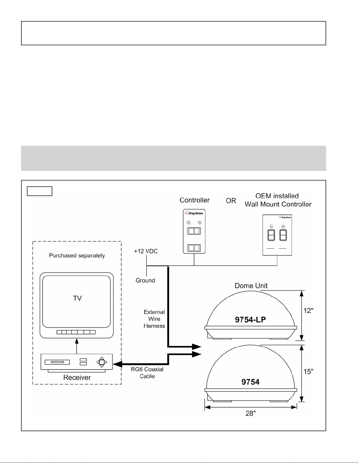
The King-Dome In-Motion Satellite System includes 2 main components (Fig. 1).
Dome (Antenna) Unit Located on the roof of the vehicle. The dish is covered by a
protective dome that keeps operational components free from
the elements.
Controller Located in the vehicle. Activates the search mode and
provides limited diagnostic functions using the status light.
SECTION 1
INTRODUCTION
Note: A TV, satellite receiver, and program subscription are also required for satellite TV
viewing. (Purchased separately.)
Fig. 1
POWER
STATUS
ON / SEARCH
OFF
TRACK
SATELLITE
PAIR
ON/SEARCH
OFF
Parked search
Press ON 3 sec.
Driving search
Press TRACK
3 sec.
TRACK
STATUS
Page 3
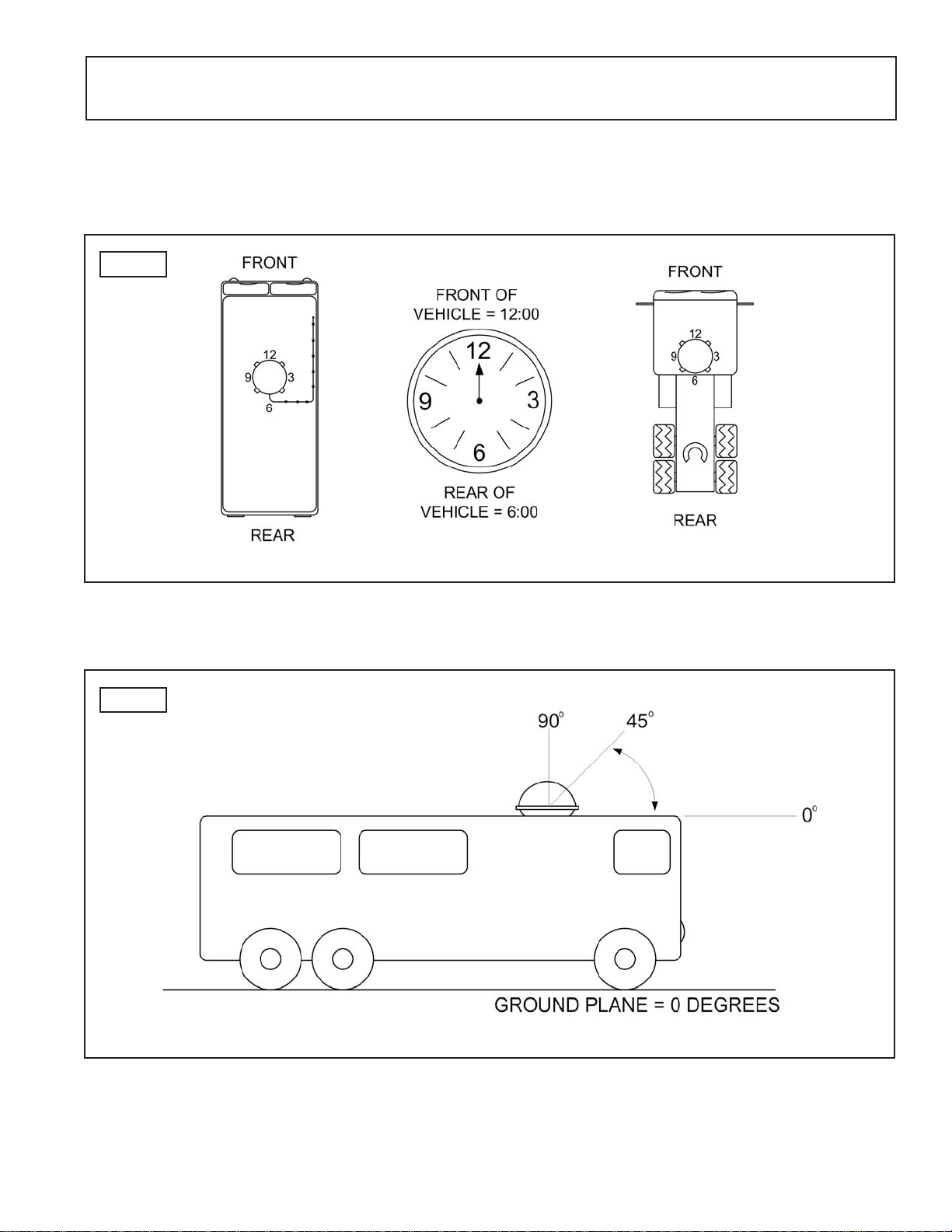
AZIMUTH: Circular rotation around the vehicle.
(like a clock face: front of vehicle is 12:00, rear is 6:00) (Fig. 2)
ELEVATION: Angle in degrees measured from the ground plane (Fig. 3).
SIGNAL STRENGTH: Intensity of electronic signal received from the satellite transmission.
SECTION 2
DEFINITION OF TERMS
Fig. 2
Fig. 3
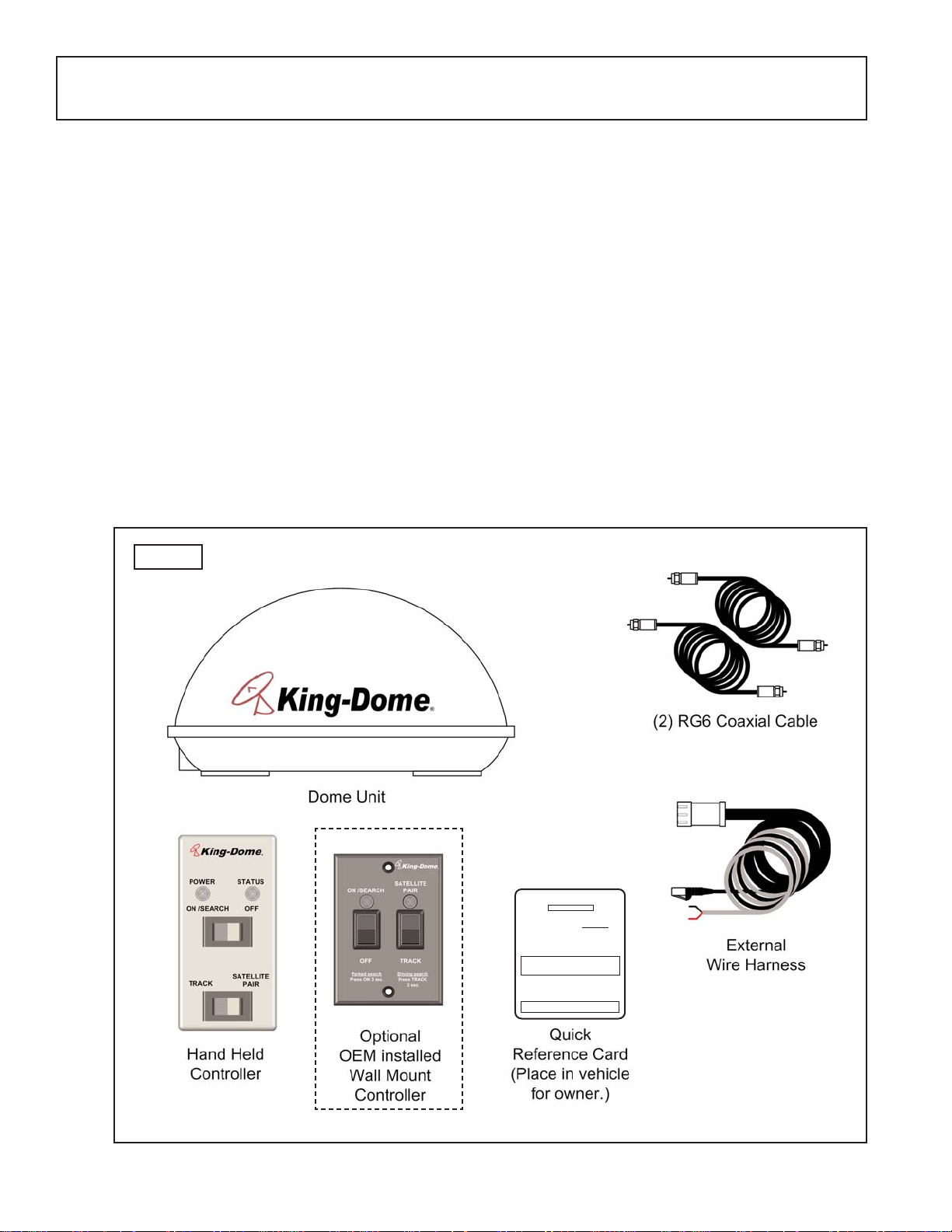
KIT CONTENTS:
1. Unpack and identify all components (Fig. 4).
Page 4
SECTION 3
INSTALLATION
Fig. 4
TOOLS AND MATERIALS REQUIRED:
- drill and drill bit set
- tape measure
- 7/16” open end wrench (coax connections)
- adhesive sealant (compatible with roof material)
- appropriate fasteners to install all components and wiring
- 5/32” allen wrench, channel lock or pliers (to remove shipping bolts)
- wire cutter (to remove shipping tie strap)
- #1844 King Controls Installation and Diagnostic Keypad
KIT CONTENTS
King-DDome
In-Motion System w/DVB
STATIONARY OPERATION
1. Turn TV and satellite receiver ON.
2. Press and hold ON/SEARCH button for 3 FULL SECONDS
.
Expect Status Light
RED -flashing . . . . . . .Searching
GREEN - flashing . . . .potential satellite found
GREEN - steady . . . . .Search Complete
Note: If the status light flashes orange after completing the
search process, there is something likely blocking the
satellite signal from reaching the antenna (tees,
buildings, etc).
2. If the search is complete and your programming does not
appear, press the reset button on your DIRECTV receiver. If
using Dish Network, hold the receiver power button in for 10
seconds to reset the receiver.
2. Select your desired channel and enjoy.
Note: To use the automatic satellite switching feature,
DO NOT turn the King-Dome OFF!
Page 5
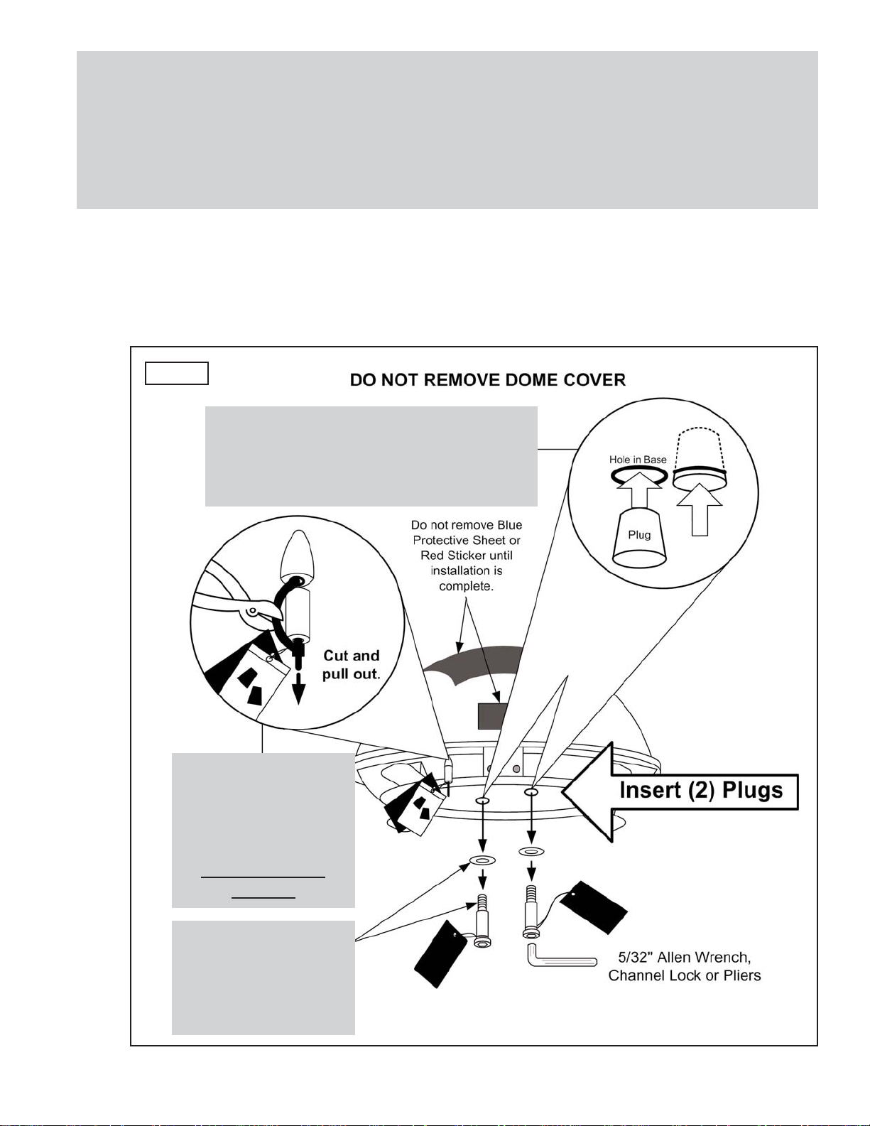
IMPORTANT! The tie strap and spacer, and the shipping bolts and washers must be
removed from the bottom of the dome unit prior to installation. DO NOT
REMOVE THE DOME COVER TO REMOVE THESE SHIPPING
RESTRAINTS.
YOU MUST PLUG THE SHIPPING BOLT HOLES WITH THE SUPPLIED
PLUGS (ATTACHED TO TIE STRAP SHIPPING RESTRAINT).
2. Remove and discard the tie strap and spacer (KEEP RUBBER PLUGS), and the (2) bolts
and (2) washers that pass through the bottom of the base (Fig. 5).
3. Insert provided plugs into holes that were occupied by the shipping bolts. Inserted plugs
should be flush with base (Fig. 5).
Fig. 5
IMPORTANT!
Remove and discard
Tie Strap and Plastic
Spacer prior to
installation.
KEEP
RUBBER
PLUGS.
IMPORTANT!
Remove and discard
Shipping Bolts and
Washers prior to
installation.
IMPORTANT!
After removing shipping bolts, firmly
insert plugs into holes. Plugs should
be flush with base.
Page 6
DOME LOCATION
4. Select an area on the roof for the dome unit and the location where the wiring will enter
the vehicle through the roof to the satellite receiver, controller, and 12 volt power source
inside, using the following criteria:
a) The shortest distance between the dome unit and the satellite receiver is most
desirable.
b) The dome unit requires a 28 inch diameter mounting area.
c) The dome unit should be mounted on the centerline of the vehicle.
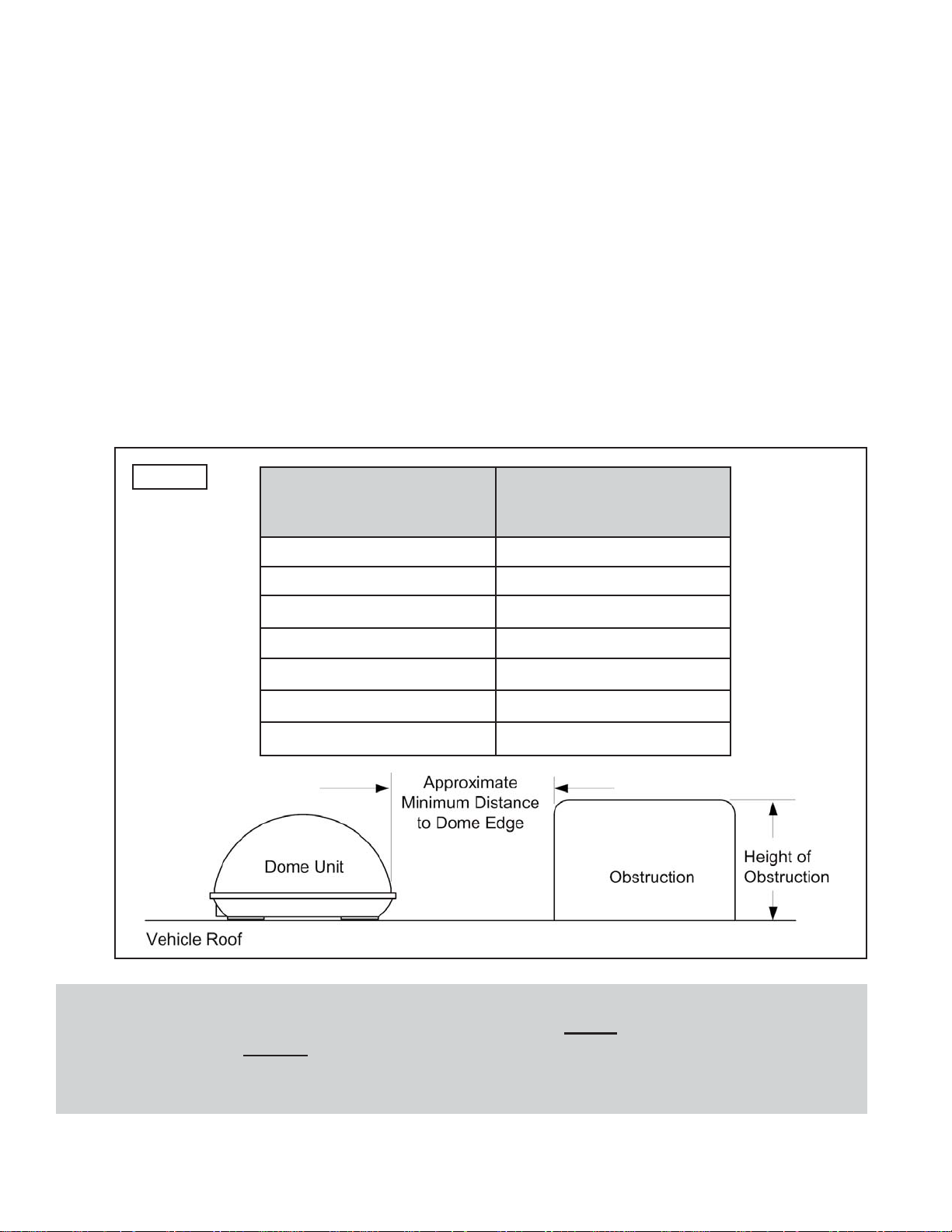
d) There must be no “line of sight” obstructions. Air conditioning units, other antennas,
and storage areas that are too close to the dome unit may prevent the satellite
signal from reaching the dish (Fig. 6).
HEIGHT OF
OBSTRUCTION
APPROXIMATE
MINIMUM DISTANCE
TO DOME EDGE
10” 8”
11” 10”
12” 12”
13” 14”
14” 16”
15” 18”
16” 20”
Fig.6
IMPORTANT! For installations on trucks with air shields, a bracket must be used for
mounting the dome unit. The dome unit MUST be mounted to the air ride
cab: NEVER
to any structure mounted directly to the frame.
See bracket instructions for proper installation (Fig. 7).
 Loading...