

KingCCTV HK-S4004 User Manual
DVR
4-channel
Digital
Video
Recorder
Manual
Table
of Contents
l.INSTALLATION
1 .1 ACCESSORY
1 .2 FRONT
PANEL
1.3 BACK
PANEL
1.4 HARD
DISK INSTALLATION
.
1.5 CAMERA
CONNECTION
1.6 MONITOR
RS485AND
RJ45
CONNECTION
1.7 REMOTE CONTROLLER
1.8
ALARM AND SENSOR CONNECTION
2.VIEW CONTROL
4
2.1
VIEW OPERATION
4
2.2 PLAYBACK
OPERATION
5
2.3 P.T.Z OPERATION
'
6
3.SYSTEM
SETUP
Z
3.1ACCESS
MENU
7
3.2 CAMERA
SELECT
z
3.3
RECORD SELECT
.
8
3.4 RECORD
MODE
e
3.5
RECORD
FRAMERATE
10
3.6
VIDEO
QUALITY
3.7 RECORD
SCHEDULE
3.8
PASSWORD,
TIMEAND
P.T.Z
SETUP
13
3.9
HARD DRIVE SETUP n
3.10
SENSOR
SETUP
1e
4.TECHNICAL
SPECIFICATION
23
S.RECORD
TIME
24
11
12

l.lnstallation
1.1
Accessory
3fl^?::l:f
"
the
accessorynshogs
'A?rbdg'A?rtpdg'
User
Manual:
4-channel
Digital
Video
Recorder
t
UU
TOr
PU
USe
I
AC
220V
Power
Cord
1
1
1
1
2 3 4
5
18
16910
14131512
Hard
disk
drive
drawer
2
f"V
1.2 Front
Panel
1.
REC
2
STOP
3, PAUSE/AUTO
4. REW/PLUS
5. FF/MINUS
6. PLAY/
SPEED
7.
MENU/IRIS
8.
CURSOR
UP/ ZOOM
9. CURSOR
DOWN/
FOCUS
1
O. SELECT
IP.T.Z
11.
CHANNEL
1/UP
12.
CHANNEL
2/LIGHT
13.
CHANNEL
3/DOWN
14.
CHANNEL
4/LEFT
15.
QUAD/STOP
16.
POWER
INDICATOR
17.DOOR
OF
FIAFD
DSKDRA'y\ER
18.
REMOTE
RECEIVER
1.3
Back Panel
1. AC
9OV-240V
POWER
JACK
2. AC9OV-24OVPO\A/ER
ON/OFF
SWTCH
3. AUDIO
INPUT
4.
AUDIO
OUTPUT
5.
VIDEO
OUTPUT
2
6. VIDEO
OUTPUTI
7.
CHANNEL
1 VIDEO
INPUT
8.
CHANNEL
2 VIDEO
INPUT
9. CHANNEL
3 VIDEO
INPUT
10.
CHANNEL
4 VIDEO
INPUT
1 1 .
SENSoR
INPUTAND
ALARM
oUTPUT
12.IDE
OF
HARD
DISK
13.
ELECTRIC
FAN
14. RJ
45
JACK
15.
RS
485
JACK
FJ45
ALAFM
Manual
1.4 Hard
Disk Drive
Installation
lnstallation
of master
hard
disk
drive:
1
. Open the door
of hard disk drive
drawer on
the
front
panel.
2. Pull out the
hard disk drive drawer and
open the top cover of it.
3.
Firmly connect
the ribbon cable
(lDE
cable) and
power
cable to the
hard disk
drive
interface
and
carefully slide the
hard
disk
into
place.
4. Slide
the cover back
into
place
and
put
the hard disk drive drawer
back into the
DVR.
Note: Check
the
hard
disk
drive's
jumper
setting. Setthe
hard
disk
drive
in the
drawer to MASTER, set
the other hard disk drive to
SLAVE.
Consult
your
hard disk drive user
manualfor instructions.
lnstallation of
slave
hard
disk
drive:
Use special
hard disk
drive drawer and
install. Installation is same
with upper
2 and 3 steps.
DVR can use 2 hard disk drive and
recom
mend to
use 7200RPM,
ATA-100 hard disk drive.
Note: When use the
new
hard
disk drive or
change another, the
hard disk
drive should be
formatted first afterturn it on.
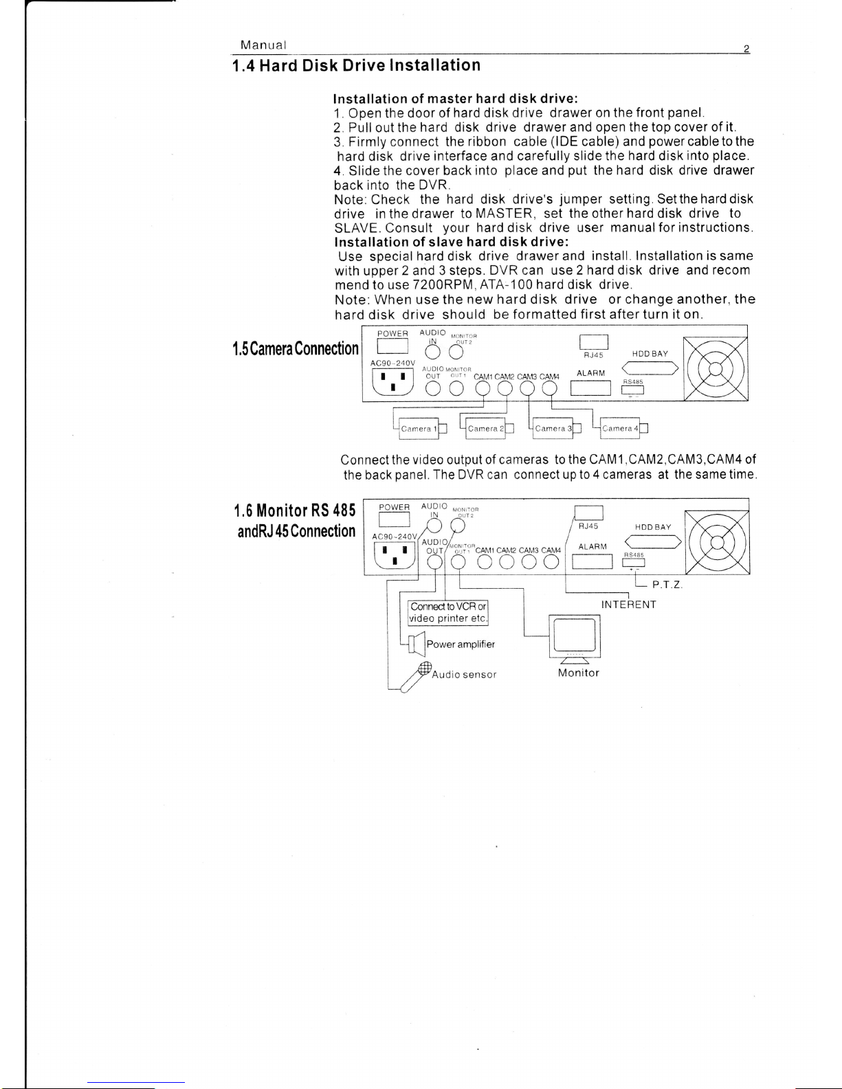
1.5 Camera
Connection
Connect
the
video
output
of cameras to the CAMl
,CAM2,CAM3,CAM4
of
the
back
panel.
The DVR can connect
up to 4 cameras
at
the same time
1.6 Monitor
RS 485
andRJ 45
Connection
AUpto,ro",ro*
lN
^LT2
| I
LI
\, \,
FJ45
AUDIO MoN ToF
I I r I
oui
-;1';;
cAMl cAl\,t2 cAI!'t3
cAM4
ALARI\'4
Lr,
OC COOO
HDD BAY
C]
8S485
lN oLrr 2 I
| | i+
I ) t l /RJ45
/o."-
ll'"cruru
cp,tttz cel,rs ceu+ |
AL
. ,-\
)
utruull
lfl
INTERENT

4-channel
Digital
Video
Recorder
1.7
Remote
Controller
MENU
UP
cH 4
DOWN
SELECT
STOP
PAUSE
P,T.Z
LEFT
AUTO
MINUS
PLUS
IRIS
FOC
U
CH1
REC
QUAD
cH2
cH3
PLAY
FF
REW
UP
STOP
RIGHT
DOWN
ZOOM
SPEED
DVR.
Manual
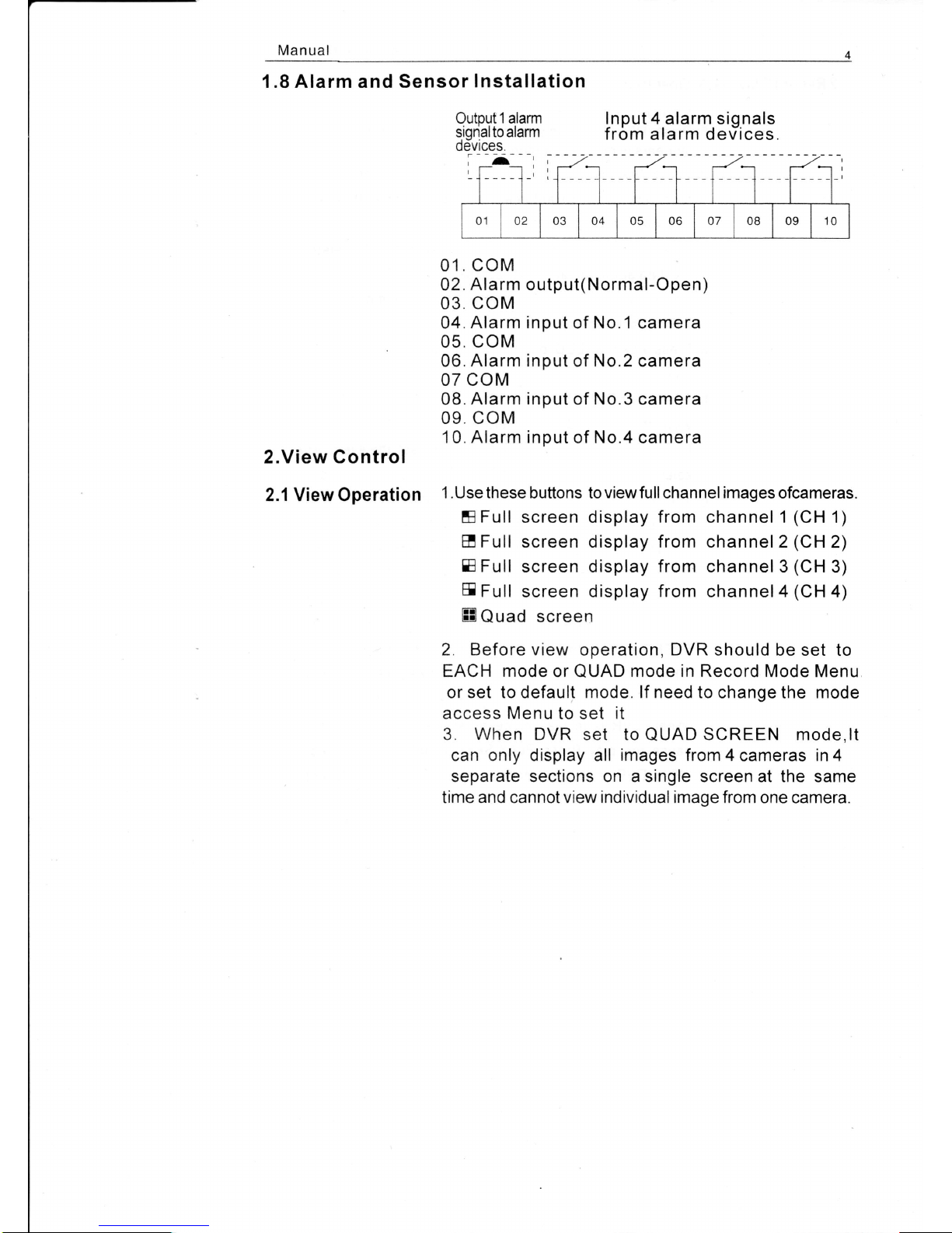
1.8 Alarm and Sensor
Installation
2.View Control
2.1 ViewOperation
Inout 4 alarm siqnals
from
alarm derTices.
01.
coM
02.
Alarm
output(Normal-Open)
03. coM
04.
Alarm input
of
No.1
camera
05. coM
06. Alarm input of No.2 camera
07 coM
08.
Alarm input
of
No.3
camera
09. coM
10. Alarm input
of No.4 camera
1 .Use these
buttons to
viewfull
channel
images
ofcameras.
EFull
screen display from channel 1
(CH
1)
E Full screen
display
from channel 2
(CH
2)
E
Full
screen display
from
channel 3
(CH
3)
E
Full
screen display
from
channel4
(CH
4)
ffi
Quad screen
2. Before view
operation,
DVR
should be set to
EACH mode or
QUAD
mode in Record Mode Menu
or set to default mode. lf need to change
the
mode
access Menu to set it
3.
When
DVR set to
QUAD
SCREEN mode,lt
can only display all
images
from 4 cameras in 4
separate sections on a single screen at the
same
time and cannotview
individual
image from one camera.
Outout 1 alarm
signalto alarm
0evrces.
I
01
o2 03 04 05 06 o7 08 09 10
5
4-channel
Digital
Video
Recorder
2.2 Record/Play
back Operation
1. Record
Operation
d.Press
REC
button
to start recording,
the smallwhite
square
appears in middle
of image
to indicate
the recording
state.
b.
When first
hard
disk
drive is full,
the DVR
cannot
stop
recording
if itset
to
automatic
overwrite
mode. lt is
recorded
in
slave hard
disk drive.
c.
lf
the slave hard
disk drive is
not
used,
the DVR
deletes
the data automatically
that
recorded
before.
The
'*'
will
appears
in image
if DVR is
in
overwrite recording
mode.
2. Playback
Operation
a.
Press PLAY/SPEED
button to
playback
the recorded
event
recently.
b.Afterpress
PLAY/SPEED
button,
press
MENU/lRlS
button
to
view
the recorded
event before Press
CURSOR
UP/ZOOM
or
CURSOR DOWN/FOCUS
button to
select the
event. After
selecting the event
,
press
PLAY/SPEED
button to view
the evenr.
c.
The specific
event can
be selected by
selecting
date
and
time.
After
pressPLAY/SPEED
button,
press
MENU/IR|S
button
toview
the
all event. Press FF/MINUS
button
to move
the cursor
to
the
date and time,
press
CURSORUP/ZOOM
or
CURSORDOWN/FOCUS
button to move the
cursor and
press
SELECT/PTZ
button
to select
the master orslave hard
disk drive
and time.Then
oress PLAY/
SPEED button
to view the event
of
the date and
time.
o.
When DVR is in
play
mode,
press
REW/PLUS
or FF/MINUS
button
to
fast
backward
play
or
fast
forwafd
play.
When DVR is in
play
mode,
press
PAUSE/AUTO
button
to
e.
p0uS€
the
play.
Press PLAY/SPEED
button
to
play
again.
When DVR is in
play
mode,
press
STOP button
to
stop the
play
and back to
QUAD
mode.

Manual
2.3
PTZ
Control
When
DVR
is in
view
mode or
record
mode,
press
SELECT/PTZ
button
to
control
PTZ.
The
buttons
on
the
front
panel
are
all
inPTZ control
function'
1.
Press the
SELECTIPTZ
button
to
control
No.1
PTZ
and
DVR
will display
PTZ CAMl
in the
lower
part
of
image.
cH1
CHz
cH3
Ch4
PTZ CAM1
2005/01/01
01:01:00
The
DVR
default
BAU
DRATE:
The DVR
default
CAMl:
01
CAM3:
03
protocol
of
PTZ:
PELCO-D
2400
addresses
ol
PTZ channels:
CAM2:
02
CAM4:
04
The
addresses
of
PTZ
channels
can
be set
to
any
of
SPEEDDOME
and
DVR
channels
2.
PT1control
operation
PTZ operation
can
control
PfZ of
relevant
channel
display
in the
image:
A.
PTZ UP
B.PTZ
RIGHT
C.
PTZ
DOWN
D.PTZ
LEFT
E. STOP
F. IRIS
CONTROL
G.
ROTATABLE
SPEED
OF
SPEEDDOME
H. ZOOM
CONTROL
I.
FOCUS
CONTROL
J.
AUTO
ROTATION
K.
PLUS
L.
MINUS
4-channel
Digital
Video
Recorder
3.System
setup
3.1Access
menu
3. When
PTZ
is in
auto
mode,
press
any
button
will
pause
the
PTZ.
Press
UP,
DOWN,
RIGHT,
LEFT
and
STOP
button
will
stop
the
auto
mode
and
change
into
manual
mode.
1 . Press
MENU/lRlS
button
to access
the
system
menu.
2. Press
CURSOR
UP/ZOOM
and
CURSOR
DOWN/
FOCUS
buttons
to
select
the item.
3. Press
SELECT/PTZ
button
to
select
and
enter.
4. Press
MENU/lRlS
button
again
to
exit
the
menu.
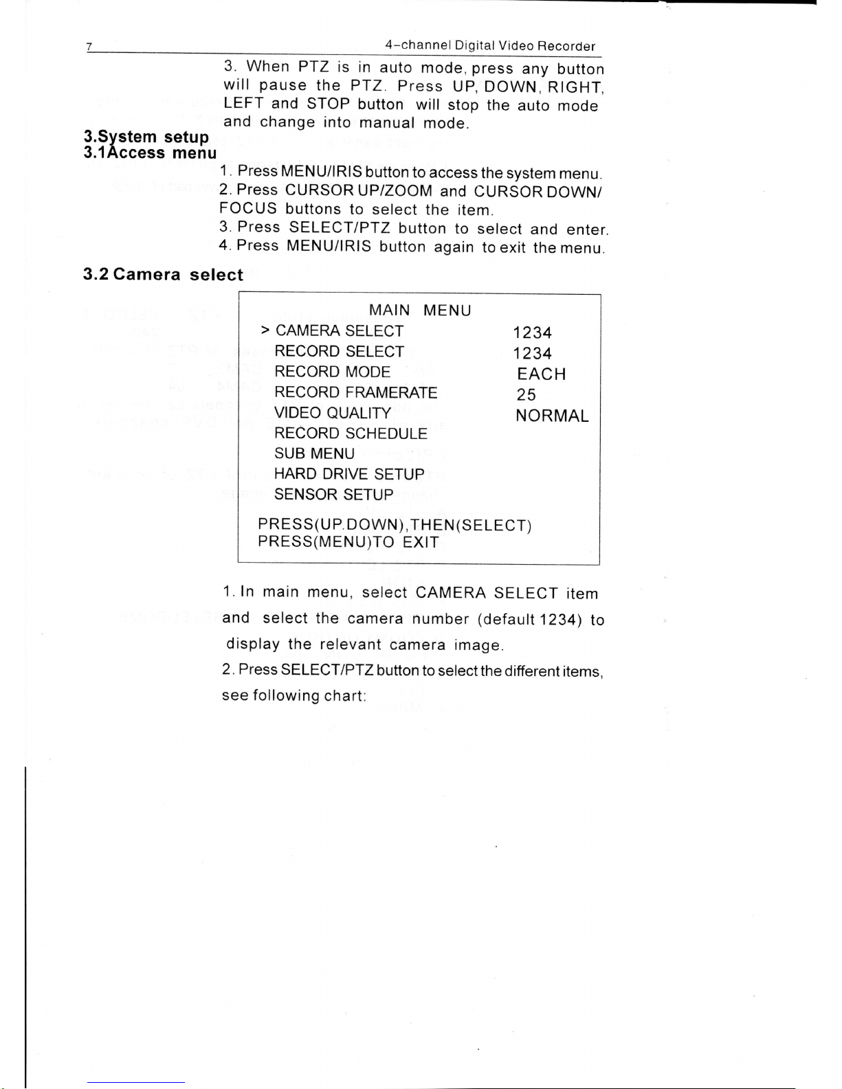
MAIN
MENU
>
CAMERA
SELECT
1234
RECORD
SELECT
1234
RECORD
MODE
EACH
RECORD
FMMERATE
25
vrDEo
QUALtry
NORMAL
RECORD
SCHEDULE
SUB MENU
HARD
DRIVE
SETUP
SENSOR
SETUP
PRESS(U
P.
DOWN),TH
EN
(SELECT)
PRESS(MENU)TO
EXIT
1.In
main
menu,
select
CAMERA
SELECT
item
and
select
the
camera
number
(default
1234)
to
display
the relevant
camera
image.
2. Press
SELECT/PTZ
button to
selectthe
different
items.
see following
chart:
3.2 Camera
select
 Loading...