

Page 1
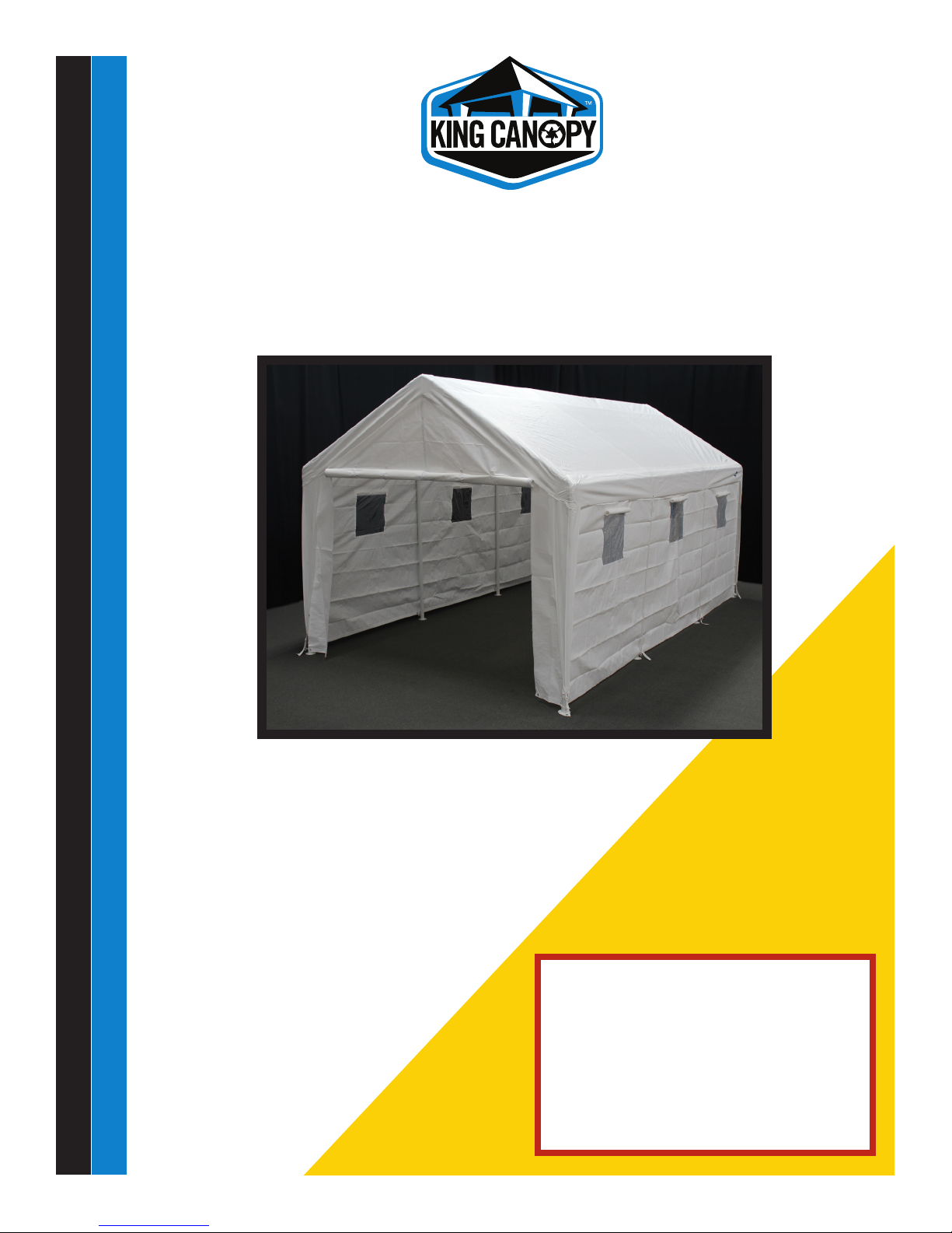
Hercules™ Enclosed Snow Load
RE U S ERE D UC E R EC YC L E
10ft X 20ft
10ft 8in Wide x 20ft Deep x 6ft 8in Side / 9ft 6in Center Height
King Canopy Item #: HC1020PCSL
With 8 Legs, King Truss™ Roof Cable System, Cover, and 4 PieceSide-Wall kit.
Distributed by:
PIC America, LTD.
1730 Five Points Lane • Fuquay-Varina, NC 27526
1-800-800-6296 • www.kingcanopy.com
WARNING:
Keep all ame and heat sources
away from this tent fabric. Meets
the ammability requirements of
CPAI-84 . It is not re proof. The fabric
will burn if left in continuous contact
with any ame source.
Page 2
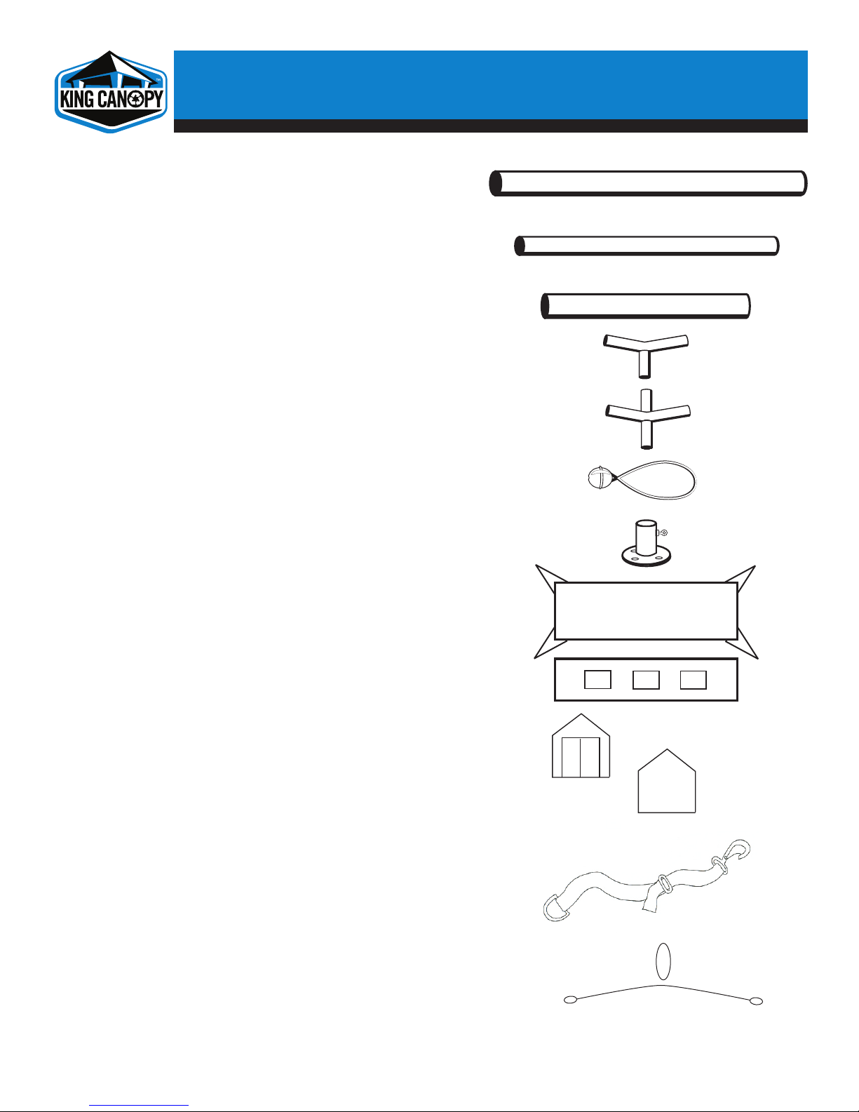
PARTS LIST
RE U S ER E DU C E R E CYC L E
6X6-2PC 8 pc 77.5in pipes, 2in diameter
6x6-15PC 9 pc 77.5in pipes, 1-1/2in diameter
5X8-2PC 8 pc 67.5in pipes, 2in diameter
3W215PC 6 pc 3-way connectors
4W215PC 6 pc 4-way connectors
BALLW 75 pc Elastic ball straps
FOOT2PC 8 pc Foot pads
PTCL1020FR6 1 pc Fitted cover w/ leg skirts
T81020SWW-WFR6 2 pc Sidewalls with windows
T81020EWZFR6 1 pc End wall with center zipper
T81020EWFR6 1 pc Solid end wall
PTCL1020VS 1 pc Valance tie downs (4 pack)
SL1020-ADJ 4 pc Adjustable King Truss™ Roof Cable System
Page 3
FRAME ASSEMBLY
RE U S ER E DU C E R E CYC L E
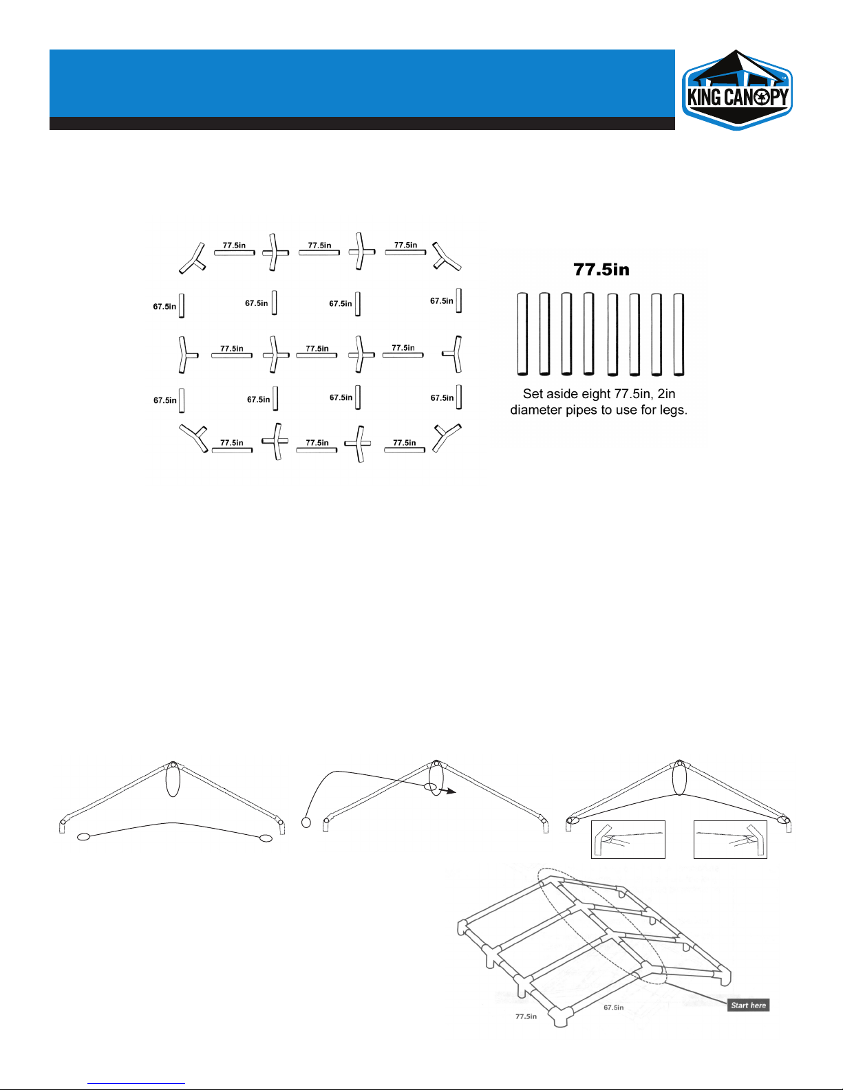
Step 1
Separate all pieces according to size and shape and arrange per the illustration shown below.
Please note:
• The 67.5in, 2 in diameter pipes are used to form the roof rafters
• The 77.5in, 1-1/2 in diameter pipes are used to form the roof perimeter
• The 77.5in, 2 in diameter pipes are used to form the legs of the unit
Step 2
As you are assembling the pipes of this unit, you will also need to begin installation of the King
Truss™ Roof Cable System. Attach the rafter pipes to each 3-way and 4-way connector beginning
at the center peak 3-ways and center peak 4-ways of each truss section. Next attach 2 rafter
pipes to each 3-way and 4-way connector, then attach the 3-way and 4-way connectors to each
end of the rafters. You should now have 4 assembled roof rafter sections laying on the ground.
Begin attaching the Roof Cables by slipping the large loop over each center ridge 3-way and 4-way connector
(Fig. A). Now pass the cable with the small outer loops through the center larger loop (Fig. B) and slip over
each end of the 3way and 4way connectors to for a completed roof truss (Fig. C). Repeat step for the other
3 roof truss sections.
Fig. A
Fig. B
Fig. C
Step 3
Connect the remaining perimeter and rafter pipes
together starting with the center of the frame,
keeping the cable truss system centered on each
section, join each truss section using the
1 1/2 in. perimeter pipes.
DO NOT CONNECT LEG POLES AT THIS POINT!
Page 4

COVER ASSEMBLY
RE U S ER E DU C E R E CYC L E
Step 1
Unfold the cover with the grommets toward the cover’s bottom and place over the frame. The ared edges
should be located at each of the 4 corners of the frame.
Step 2
Begin attaching the cover with the elastic ball straps by inserting the elastic cord of the ball strap underneath
the cover and through the grommet. Then pull cord taut until ball stops. Wrap the cord around the pole and
under the ball. This will hide the ball under the cover and provide a more nished look to your unit.
• Start by attaching 2 elastic ball straps at each of the four corners
• Continue attaching straps from left to right in a zigzag pattern down both sides of the canopy
• Attach straps at the front and back of the unit, again using a zigzag pattern until all straps are secured
Note:
The ball straps are long enough to accommodate various cover lengths. If your straps need a tighter t, they
can be shortened by making an additional knot in the cord strap.
Slide the ball upward to reveal the tied knot.
Tie a new knot above the old one. The size of the knot will determine how short the strap becomes. Slip the
ball down over the new knot and secure.
DO NOT CONNECT LEG POLES AT THIS POINT!
Page 5

WALLS AND LEGS ASSEMBLY
RE U S ER E DU C E R E CYC L E
Step 1
Unfold each of the walls.
• The front wall features 3 zippers, one on each side and one in the center.
• The rear wall is solid woth no zippers.
• The side walls of the unit feature 3 windows each
Step 2
Find the hook & loop fastening strips on one length of the rst sidewall to be assembled. These strips are to
be placed on the top pipe of your canopy structure by wrapping the fastening strips over the perimeter poles.
Repeat with second side wall, rear wall and front wall.
Note:
You may attach the side and rear walls with the window shades facing either the inside or outside of the unit.
They are designed to be assembled either way.
NOW, CONNECT THE LEG POLES TO THE ROOF ASSEMBLY WITH THE COVER ALREADY POSITIONED ON
TOP OF THE UNIT.
Step A: First insert the pipes for the middle poles into the 3- and 4-way
connectors, and then connect the end leg pipes in the same way.
(See illustration)
Step B: Push the eight foot pads onto the bottom of each leg.
NOTE: the foot pads are NOT for anchoring the canopy!
Step C: Connect the hook & loop fastening strips down
the length of each leg.
Step 3
After connecting the top of the side walls and installing the leg pipes into the connectors on the perimeter of
the unit, use elastic ball straps to connect the end of each sidewall to the 4 corners of the unit.
IMPORTANT! Once the legs and cover are assembled, your canopy will act like a kite in the wind. It is
imperative that the canopy anchors be installed NOW!
Page 6

ANCHORING YOUR UNIT
RE U S ER E DU C E R E CYC L E
This canopy is designed for use as a temporary structure. After assembly, the canopy MUST BE securely
anchored to the ground to prevent damage from winds. Your canopy will act like a kite in the wind if not
properly and securely anchored to the ground. Severe winds will cause the frame to twist and unanchored
legs will fall, thereby collapsing the canopy. If severe winds are expected, you must remove the cover from
the frame to prevent damage.
Step 1
Measure out at least 36in from each leg. Screw each anchor into the ground leaving 2in between the ground
and the eye of each anchor. We strongly recommend that your unit be anchored 36in from each leg
although this may not be possible in all cases. DO install anchors as close to 36in away from legs as possible.
Step 2
Tie anchor cable or rope around the connector at the top of each leg of the canopy.
Step 3
Securely tie the other end of the cable or rope through the eye of the anchor and pull tight.
Step 4
Now, continue to screw each anchor into the ground until the eye of the anchor is ush with the ground. This
will secure the anchor rope even tighter.
NOTE: You should check and tighten the rope frequently to ensure maximum stability of your canopy and to
protect against wind damage.
ANCHOR KIT NOT INCLUDED
Page 7

INSTALLING THE LEG SKIRTS
RE U S ER E DU C E R E CYC L E
Step 1
After the legs have been connected to the roof using the 3- and 4-way connectors and your canopy has been
securely anchored, attach the leg skirts using elastic ball straps and the grommets at the top of the unit.
(Make sure that the end walls are underneath the ared leg covers to minimize rain and other elements from
entering inside the canopy unit.)
Step 2
Next secure the ared leg covers over the 4 corners (and outside the walls) by fastening the fabric loops
located at the bottom of each leg skirt over the anged clip on the foot pads.
FINISH ASSEMBLY OF YOUR CANOPY
To complete the assembly and securing of your unit, nish installing elastic ball straps completely around the
unit at the top and bottom wherever there is a grommet. Ball straps at the bottom of each side panel should
be attached to the anged clip on the foot pads.
Lastly, attach the 4 valance tie downs from the top grommet to the bottom grommets, securing to the foot
pads using the clips on end of the straps.
Page 8

IMPORTANT NOTICE: PLEASE READ CAREFULLY
RE U S ER E DU C E R E CYC L E
We are condent that you will be completely satised with your King Canopy unit. Please take a moment
to read the very important information below, and call us with any questions you may have.
King Canopy/PIC America, LTD. has no control over wind, snow, ice, rain or any other weather condition and
we are in no way responsible for any damage caused by the canopy or to the canopy. We suggest you contact
your insurance carrier just as you would for any other outside structure.
OTHER PRECAUTIONS WHICH MUST BE FOLLOWED:
Keep all ame and heat sources away from this tent fabric. The tent fabric will burn if left in continuous
contact with any ame source.
DO NOT cook underneath or near canopy.
DO NOT store or use ammable liquids underneath or near canopy.
DO NOT ignite or store reworks underneath or near canopy.
DO NOT use bleach to clean cover.
DO NOT dry clean cover.
DO NOT wash cover in washing machine or dry in dryer. Hand wash with mild soap and water only.
DO NOT allow rain water, snow or ice to accumulate on top of cover.
DO NOT hang or suspend anything from the frame, grommets, truss system or ball straps of the unit.
REMOVE canopy cover before a storm, or disassemble entire canopy unit if possible.
REMOVE rain water, snow and ice from canopy cover.
This is a temporary structure and is not recommended for use as a permanent structure.
Page 9

PRODUCT INFORMATION
RE U S ER E DU C E R E CYC L E
Defective Parts
We try our best to eliminate any defective parts that are shipped with our products. If, however, you should nd
a defective part, we will replace – free of charge – any part which is defective. You will need to provide proof
of purchase showing date of purchase and provide us with detailed description of the defective component.
Your replacement will be shipped by ground shipping, freight prepaid. Next day or express shipping will
require freight collect and paid for by you, the consumer. Damages from improper anchoring, strong winds,
snow, ice or rain are not considered defects.
Improper Anchoring, Strong Winds, Rain Snow, or Ice
King Canopy/PIC America, LTD. does not guarantee these canopies under strong weather conditions. These
canopies are designed to protect against damages caused by sun, rain, tree sap, birds, etc. They are not designed
to hold roof loads that accompany snow, ice or heavy rains. If your canopy is not anchored securely, it can be
lifted by the wind and will y away. If your canopy takes ight, we are not responsible for any replacement. If
you know strong weather is predicted, remove the cover or take down the canopy unit completely. The cover
is designed to be quickly and easily removed.
Warranty
All components of this canopy feature a 1-year limited warranty and are warranted to be free from defects in
material and workmanship for a period of 1-year. You must complete and return the enclosed warranty card
promptly after purchase. Please retain your proof of purchase receipt; you will be asked to provide this receipt
in order to obtain warranty service.
Non-Warranty Replacement Parts
If after expiration of the warranty period, you require replacement parts please contact us at 1-800-800-6296.
We stock replacement parts and make them available to you at discounted prices. Our customer service
department will be pleased to assist you in any way possible.
Certain regions of the country are extremely hard on covers of any kind. Normal wear and tear is not covered
under the warranty, and should be expected.
In order to receive a discounted or free replacement part, you may be asked to return the part, freight prepaid,
to our warehouse for inspection before we will send a replacement. You must, in all cases, provide a copy of
your receipt showing the date of purchase, model number and price.
For missing parts, replacement parts or any questions:
Please Call 8:00am – 5:00pm EST, Monday –Friday
1-800-800-6296 or 1-919-552-2977
Or you can fax us at: 1-919-552-5069
Replacement parts and customer service is also available through our website.
Please visit us at www.kingcanopy.com
 Loading...