

Page 1
SAVE THESE INSTRUCTIONS
GENERAL INFORMATION
WinDow Watcher
WR & WRP Series
System Matched for King heaters
DANGER
ELECTRIC SHOCK OR FIRE HAZARD
READ ALL WIRE SIZING, VOLTAGE REQUIREMENTS AND SAFETY
DATA TO AVOID PROPERTY DAMAGE AND PERSONAL INJURY
!!
™
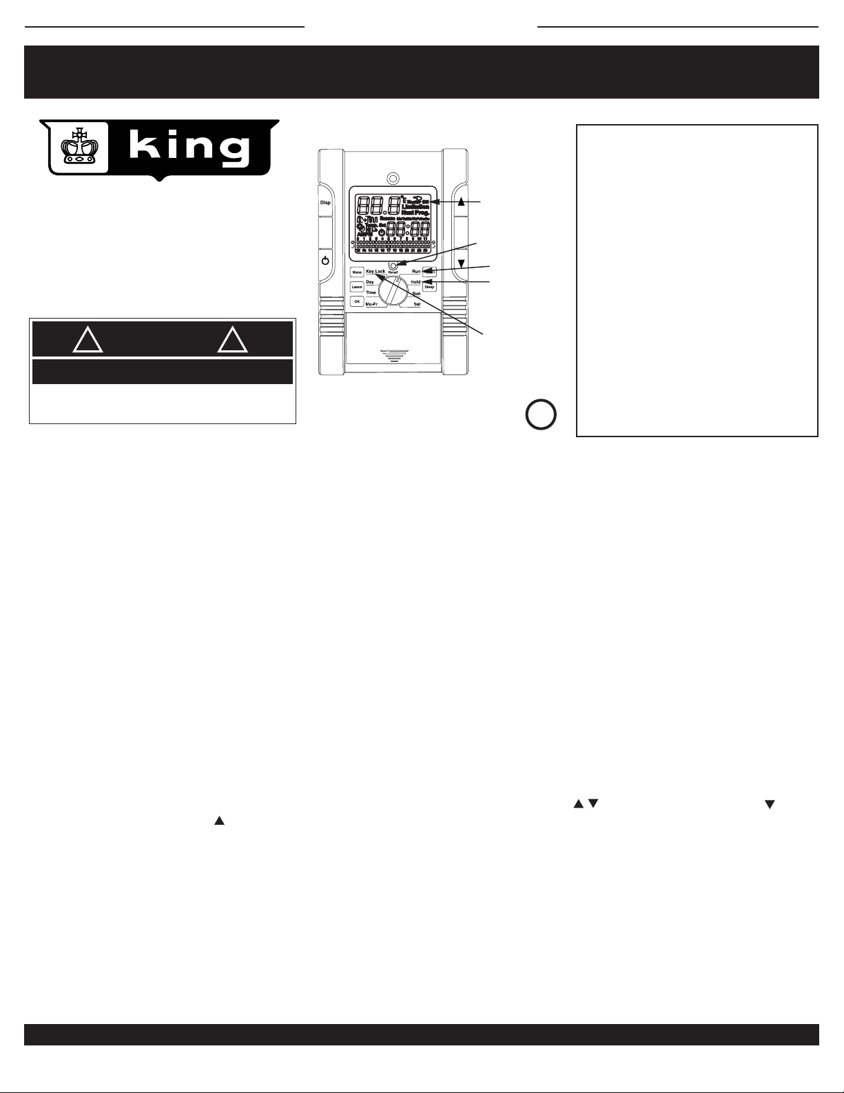
WRP SHOWN
HEATER ON INDICATOR
RESET: BACK TO PRESETS
TAMPERPROOF
KEY LOCK
PATENT APPLIED FOR
RUN: DAY AND TIME
*HOLD BUTTON:
RUN PROGRAM /
HOLD TEMPERATURE
*WRP model only
U
®
CUS
LISTED
SPECIFICATIONS:
Temperature range: 40° to 75°F
Temperature Default: Your set point
Display Format: Liquid Crystal Display (LCD)
Display size: Large Format
Sample Rate: Every 60 seconds
Delay on or off: 3 minutes
Heat indicator: LCD “heater on”
Relay Rating: 16 Amps inductive/resistive
Accuracy: ± .9°F
Maximum Amps: 16 inductive continuous
Maximum Watts: 3840 @ 240V or 1 hp
3328 @ 208V or ¾ hp
Total inductive motor load combined can not
exceed 16 Amps
Minimum Watts: 0
Power Supply: 208 to 240 Volts AC
L
200 to 250 Volts AC
GENERAL INFORMATION:
This thermostat is designed to reinforce positive energy habits while limiting landlord energy expenses. For use on 208 / 240 Volt AC and a total of 16 Amps
load inductive continuous.
Almost all residential application electric heaters installed as original equipment by an electrician will be 208 or 240 Volt. It is very rare that a home, apartment
or condominium would be wired with all 120 Volt heaters. Check the voltage to make sure you have the right thermostat for your heater voltage. A 2-pole or
double-wide circuit breaker at the panel indicates a 240 Volt circuit; A 1-pole or single-wide breaker indicates a 120 Volt circuit. There are some exceptions to
this rule; Check with a voltmeter to determine accurate phase to phase voltage.
Be safe and smart! Electricity can cause severe injury or death if not treated with respect and caution.
This thermostat will provide years of comfort control for your family in use with small fan-driven electric heaters, baseboards, radiant ceiling or wall panel
heaters, cove heaters, or any line voltage resistance heating systems that do not have an electric motor over 1/3 hp.
OPERATION:
The Window Watcher™ is a precision electronic thermostat and uses a very sensitive thermistor near the bottom to sense room air temperature, sending
the information on to the microprocessor. As the temperature drops, the information sent will indicate if heat is needed. To reduce any undesirable fast on/off
cycles, the processor has a built-in delay, up to 3 minutes. This saves energy and provides the best temperature control of an area.
The
Window Watcher
40°F temperature is a fixed setting and not adjustable. The maximum operating temperature is stopped at 75°F, helping to change human behaviors that
increase energy costs. The day and time of day can be adjusted by selecting the TIME position and using the arrow keys. For an override, the UP
arrow increases temperature and the DOWN arrow reduces temperature without any need to readjust the programming.
The thermostat may take a few hours to stabilize the room temperature; Do not be alarmed when the thermostat does not show the correct temperature
immediately after installation.
™
thermostat has an extra contact terminal block for remote set back to 40°F. Intended for window or door open contacts. The
INSTALLATION:
This line voltage device should be installed and serviced by a qualified electrician. The thermostat has been designed to mount to a standard 2" x 4" electrical
outlet box. Leveling of the thermostat is not required. #6-32 Phillips head mounting screws are provided.
Mount the thermostat in an open area about 5 feet above the floor, avoiding outside walls as they are too cold and will inhibit the thermostat’s performance. A
good rule of thumb is to place the thermostat above the wall switch for that room. This works well for most bedrooms, making it very convenient to turn the heat
lower upon leaving. Avoid mounting the thermostat where there may be plumbing pipes in the wall, or placing a lamp or TV too close to the thermostat. Heat
KING ELECTRICAL MFG. CO. · 9131 10TH AVENUE SOUTH · SEATTLE, WA 98108 · PH: 206.762.0400 · FAX: 206.763.7738 · www.king-electric.com
WRP information.ai : 12/09
Page 2

SAVE THESE INSTRUCTIONS
INSTALLATION AND MAINTENANCE
DISPLAY LEGEND - WR & WRP
WINDOW CONTACTS
(back side)
HEATER ON INDICATOR
DAY OF WEEK
TIME OF DAY
SET TEMPERATURE
UP OR DOWN
REPLACES MODELS: CALV / T4800 / T4700 /
T4600 / 1A65 / 1A66 / D22 / S22 / M601 / M602 /
T498 / T4398 / MD26 / WR661 / 1D22 / C901 /
C902 / S2022 / TW242 / TD902 / T410 / TD942 /
M7 / M402 / M512 / K601 / HE-1
WinDow Watcher
™
WR230 & WRP230 Series
DANGER
ELECTRIC SHOCK OR FIRE HAZARD
READ ALL WIRE SIZING, VOLTAGE REQUIREMENTS AND SAFETY
DATA TO AVOID PROPERTY DAMAGE AND PERSONAL INJURY
!!
DISPLAY CHANGE
TEMPERATURE
WAKE, LEAVE,
RETURN, SLEEP
WARNING
!!
READ CAREFULLY - These instructions were written to help prevent difficulties that might arise during thermostat
installation. Studying the instructions first may save considerable time and money later. Observing the following
procedures will keep installation time to a minimum. Save these instructions for future use.
U
L
®
CUS
LISTED
PATENT APPLIED FOR
Thank you for buying this King Window Watcher™ thermostat. It should provide years of service and comfort to your home. Inspect the package.
Enclosed should be the thermostat with its cover and two screws.
1. Check the total load of the heaters being connecting to the thermostat. The maximum wattage at 240 Volt is 3840 Watts, 208 Volt is 3328 Watts,
and 16 Amps. It is important to stay below this total wattage when connecting the thermostat. Lower wattage prolongs the the life of the contacts
in the relay.
2. To wire the thermostat determine which pair of wires are coming from the breaker panel and which pair lead to the heater. See Wiring Instructions.
3. Remove cover of thermostat by placing thumb on LCD display and fingers on top edge of cover. Pull towards you. This will expose the top
mounting screw.
4. There may be a pair of white wires connected in your junction box. If so, leave them alone and, at this time, work with the black wires.
5. Take a black lead and attach it to the black lead on the thermostat.
6. Take the other black heater lead and attach it to the red lead on the thermostat. This will provide power to the heater when the thermostat calls
for heat. Add blue wire to both white wires to provide power to electronics.
7. Push the wires carefully into the junction box making sure no wires are pinched or will obstruct the screws mounting the thermostat. Now attach
the thermostat to the wall using the #6-32 Phillips head screws provided. Replace cover. Do not over tighten screws.
8. Replace cover after setting time and programming.
9. Turn on power. Test by increasing set point to higher than current room temperature by tapping the Up button. There will be up to a 3 minute
delay in turning on. You will hear a small click and “Heater On” will appear in the LCD; the heater should be on now. Turn the thermostat down
by tapping on the Down arrow.
10. You have now verified the thermostat is in perfect working order and ready for years of trouble-free operation.
11. Mounting tips: Make sure nothing is nearby (a.g. plumbing pipes in the wall, a lamp close by, direct sunlight, a T.V. set, and/or cold
drafts from a door opening) that could affect the average room temperature sensing of the thermostat. Typically the best, most convenient
location is on inside walls above the light switch for that room.
12. Cleaning: Canned compressed air works great to clear any dust accumulation, while a damp cloth will additionally clean the plastic case surface
of finger prints. Strong spray cleaners may damage the plastic case or remove writing or arrows screen-printed on case. Blow out any dust that
may accumulate on top or bottom air vents. Good air circulation is key to long life and accurate operation.
13. Humid locations: Mildly humid location like bathrooms may reduce life due to corrosion on the contact and lint from towels getting into
thermostat air vents. To extend life blow out vent regularly and mount thermostat away from shower locations.
KING ELECTRICAL MFG. CO. · 9131 10TH AVENUE SOUTH · SEATTLE, WA 98108 · PH: 206.762.0400 · FAX: 206.763.7738 · www.king-electric.com
WRP installation.ai : 12/09
Page 3

WRP230
WINDOW WATCHER
SAVE THESE INSTRUCTIONS
Comfort and Economy Setting
Independent Daily Time Schedule Setting
Clock
Manual (Temporary Override)
Window Watcher
mode
Hold
Motion Detecting
WRP230
1
Comfort and Economy Setting
To adjust setup (comfort) and setback (economy)
temperatures.
1
Turn rotary switch to START.
2
Press twice to enter room temperature
“HI” (comfort) setpoint. Press or to adjust.
Press to exit.
3
Press twice to enter room temperature
“LO” (economy) setpoint. Press or to adjust. Press to exit.
4
Wait 5 seconds after adjusting the temperature. The thermostat shall
memorize setting and return to the main screen.
This thermostat has only two air temperature settings: 7 independent days
and 30 minute increments. Users can adjust Comfort and Economy
time to their schedule many times per day.
2
Clock
1
Turn indicator on rotary switch to “START”.
2
Press to enter clock programming.
3
Press or to select the day of the week.
4
Press again to adjust hour of day.
5
Repeat pressing and to finishing setting the time.
6
LCD display shall automatically memorize the setting and return to the main
screen 5 seconds after time is set.
WINDOW WATCHER
™
PROGRAMMING INSTRUCTIONS
4
Hold
Reset
Reset
STARTMO 1
SU 7TU 2
SA 6WE 3
FR 5TH 4
STARTMO 1
SU 7TU 2
SA 6WE 3
FR 5TH 4
Press “HOLD” for constant temperature.
5
Manual (Temporary Override)
1
Turn indicator on rotary switch to “START”.
2
Press or to indicate current or
temperature settings.
3
Press or to adjust temperature setting.
4
The LCD display will flash for approximately 8 seconds after temperature setting
is complete then return to the main LCD display screen. The thermostat will now
begin to execute the Manual function.
5
Turn the rotary switch away from “START” then turn it back to “START” to
terminate the Manual function.
When in Comfort while setting the Manual function the thermostat will
maintain executing Manual until the program runs to Economy .
The same is true in Economy .
The and icons will disappear from the LCD at the section of time the
Manual function is operating.
5
Window Watcher
Any remote contacts can be used to activate the 40° set back. Multiple contacts
can be placed in series so that if any break in the small 22 gauge control wire
is sensed the thermostat will display “OFF” on the LCD window. As soon as the
window contacts are closed the thermostat will resume operating like normal (the
previous setting before the contacts were opened).
™ mode
ENERGY STAR
PATENT APPLIED FOR
STARTMO 1
Reset
SU 7TU 2
SA 6WE 3
FR 5TH 4
3
Independent Daily Time Schedule Setting
If the dial is left in anything but the START position it will default to “ERR”
(Error). Turn to START to clear Error and restart programming.
Factory default settings are 70°F/21°C and 61°F/16°C .
1
Turn indicator on rotary switch to the desired week day to
begin programming time.
2
Press or to alter the setting between
and on the LCD display.
3
Press or to select each individual time schedule. Each time schedule
will be indicated by flashing symbols.
4
After setting all 7 days of the week turn rotary switch to “START”. The
thermostat will now start to operate its program.
Reset
In 40° set back mode
(window open)
STARTMO 1
SU 7TU 2
SA 6WE 3
FR 5TH 4
5
Motion Detecting
Optional motion detecting can set back to 40°F (or to a higher 60°F) if required.
WRP programming.ai : 12/09
Page 4

WIRING INSTRUCTIONS
WinDow Watcher
SAVE THESE INSTRUCTIONS
™
1 1/8"
WINDOW
CONTACTS
COMMON WIRING
BLACK
WHITE
U
L
®
CUS
LISTED
PATENT APPLIED FOR
WR & WRP Series
System Matched for King heaters
DANGER
ELECTRIC SHOCK OR FIRE HAZARD
READ ALL WIRE SIZING, VOLTAGE REQUIREMENTS AND SAFETY
DATA TO AVOID PROPERTY DAMAGE AND PERSONAL INJURY
1. To wire the thermostat determine which pair of wires are coming from the
breaker panel and which pair lead to the heater.
2. Take a black lead from the circuit breaker panel and attach it to the black
lead on the thermostat.
3. Take the black lead that goes to the heater and attach it to the red lead on
the thermostat. This will provide power to the heater when the thermostat
calls for heat. Attach the blue wire to the white wires.
4. Remove cover of thermostat by placing thumb on LCD display and
forefinger on top of cover, pulling cover back to expose mounting screws
and programming buttons. Slide battery cover off to expose lower
mounting screw.
5. Push the wires carefully into the junction box making sure no wires are
pinched or obstruct the screws mounting the thermostat. Now attach the
thermostat to the wall with the #6-32 Phillips head screws provided.
6. Hold thermostat in wallbox and place screws in top and bottom mounting
hole. Attach to wallbox. Install batteries and replace cover.
7. Turn on power. Test by increasing set point to higher than room
temperature by tapping the Up button. There will be up to a 3 minute
delay turning on. You will hear a small click and “Heater On” will appear on
the LCD; the heater should now be on. Turn the thermostat down by
tapping on the Down arrow.
8. Differential Adjustment: Hold both temperature and buttons for 10
seconds. The screen will go blank then show one digit. This is the number
of degrees that the thermostat will over or undershoot the desired
temperature. Adjust the setting between 1° and 4° by tapping the or
arrow. Adjust to suit your comfort level.
* To change the display from Fahrenheit to Celsius requires opening the thermostat and moving a small
jumper on circuit board. For assistance please contact the factory at (800) 603-5464 ext. 111
!!
40° set back on
open contacts
Optional:
60° set back on open
POWER IN
BLACK
RED
1 5/8"
LINE 1
BLACK
WINDOW
CONTACTS
DOOR
CONTACTS
MOTION
SENSOR
BLACK
BLACK
HEATER - UP TO 3840 WATTS
DIMENSIONS:
3 3/8" 1 1/8"
2X4
JUNCTION
BOX
BLUE
BLACK
TO HEATER LOAD
RED
WHITE
COMMON
WHITE
BLUE
THERMOSTAT
CIRCUIT
BREAKER
LINE 2
WHITE
JUNCTION BOX COVER
The small 22 gauge wire connection on the back of the thermostat is for the
remote 40° activation. This is a volt-free set of control wires that can be used
with any switch, such as: window and door contacts, motion sensors, key
cards, hotel panels, anything that can make or break contact.
40° set back is activated on contact open.
KING ELECTRICAL MFG. CO. · 9131 10TH AVENUE SOUTH · SEATTLE, WA 98108 · PH: 206.762.0400 · FAX: 206.763.7738 · www.king-electric.com
5 1/4"
WRP wiring.ai : 12/09
 Loading...