

Page 1
Adjustable Electronic Thermostat TRACON® Model SST–3 (P/N 24492)
Instruction Manual
SAFETY INFORMATION AND WARNINGS
Pilot Duty
The SST–3 Adjustable Electronic Thermostat with GFEP cannot be used for Pilot
Duty applications.
Resistive Load Usage Only
This product is not for use with Inductive loads. Inductive loads may create
nuisance tripping of the Ground Fault Equipment Protection circuit.
Abnormal Odor or Smoke
In the event of smoke or a burning or abnormal odor, immediately interrupt power
to the unit by turning off the circuit breaker protecting the unit.
Electrical Shock / Fire Hazard
Any installation involving electric heater wiring must be grounded to earth to
protect against shock and fire hazard. Suitable ground fault detection and
interrupting systems must be in use at all times to reduce shock and fire hazard
and to protect equipment.
Electric wiring to heating elements must be installed in accordance with National
Electrical Code (NEC) requirements, as well as all other local and applicable
electrical codes and any third party standards. Follow the installation instructions
contained in this manual and also those provided by the heater manufacturer.
Size the circuit breaker in accordance with the size of the expected load. The
maximum current load for the SST–3 is 30 Amp resistive. This product is
intended for use in light commercial applications.
Make certain that the heater shield is properly grounded. Failure to do so may
result in damage to the equipment or fire.
Following installation and prior to beginning system operation, perform the PostInstallation Test described in this manual.
24494 Rev. - 04/12 (800) 234-4239 http: www.networketi.com En vironmental Technology, Inc. 1 of 28
Page 2
Adjustable Electronic Thermostat TRACON® Model SST–3 (P/N 24492)
Instruction Manual
PRODUCT TESTING RECORD
Use this page to record the results of the Mega-Ohm test procedure in this
manual. This record will be a useful resource throughout the life of the product.
MEGA-OHM TEST (Page 9)
(Follow heat tape manufacturer’s recommendations or, if not available,
use a 500 VDC mega-ohm meter on the heat tape.)
TEST
DATE
AMBIENT
TEMPERATURE
Check heat tape manufacturer’s documentation.)
(Target: 20 MΩ or greater;
READING
24494 Rev. - 04/12 (800) 234-4239 http: www.networketi.com En vironmental Technology, Inc. 2 of 28
Page 3

Adjustable Electronic Thermostat TRACON® Model SST–3 (P/N 24492)
Instruction Manual
TABLE OF CONTENTS
SECTION PAGE
Safety Information and Warnings ------------------------------------------------------- 1
Product Testing Record ------------------------------------------------------------------- 2
Unpacking the Unit ------------------------------------------------------------------------- 4
Inventory -------------------------------------------------------------------------------------- 5
Product Description ------------------------------------------------------------------------ 6
Installing the Control ----------------------------------------------------------------------- 7
Preparation and System Set-Up -------------------------------------------------------- 9
System Schematic Diagrams ----------------------------------------------------------- 10
Post-Installation Testing ----------------------------------------------------------------- 13
Operation ------------------------------------------------------------------------------------ 15
Ground Fault Operation ------------------------------------------------------------------ 20
Error Codes --------------------------------------------------------------------------------- 21
Maintenance -------------------------------------------------------------------------------- 22
Using the Jumper -------------------------------------------------------------------------- 23
Troubleshooting ---------------------------------------------------------------------------- 24
Specifications ------------------------------------------------------------------------------- 26
Ordering Information ---------------------------------------------------------------------- 28
24494 Rev. - 04/12 (800) 234-4239 http: www.networketi.com En vironmental Technology, Inc. 3 of 28
Page 4

Adjustable Electronic Thermostat TRACON® Model SST–3 (P/N 24492)
Instruction Manual
UNPACKING THE UNIT
Immediately upon receipt, inspect the container and packing material for any
noticeable damage. Unpack the unit, taking care not to damage the packing
materials. Save the shipping container and related materials until normal
operation has been established. If the unit must be returned, take care to ensure
that it is repackaged as it was received.
As soon as the unit arrives at your facility, inspect it for mechanical damage. If
any of the following problems is found, contact Environmental Technology, Inc.,
Customer Service immediately:
contents incomplete or incorrect;
internal or external mechanical damage; or
defective operation.
ETI Customer Service is available between 8:00 a.m. and 5:00 p.m. Eastern
Time at (574) 233-1202 or (800) 234-4239. In the event of shipping damage,
keep the packing materials for inspection by the carrier.
RETURNS AND REPLACEMENT PART PURCHASES
Equipment cannot be returned for credit once it has been installed. ETI will
repair or replace faulty equipment under warranty. Prior to removal of equipment
for warranty return, please contact ETI Technical Support at (800) 234-4239 for
troubleshooting assistance.
Before returning a unit to Environmental Technology, Inc., obtain a Return
Merchandise Authorization from our Customer Service Department, available
between 8:00 a.m. and 5:00 p.m. Eastern Time at (574) 233-1202 or (800) 234-
4239. If possible, use the original container and packing materials when packing
the unit for shipment. It is important to mark the Return Merchandise
Authorization clearly on the outside of the shipping container so that it may be
correctly processed upon receipt at Environmental Technology.
For more information about replacement parts or for a replacement Data Sheet
or Manual, please visit http://www.networketi.com/.
24494 Rev. - 04/12 (800) 234-4239 http: www.networketi.com En vironmental Technology, Inc. 4 of 28
Page 5
Adjustable Electronic Thermostat TRACON® Model SST–3 (P/N 24492)
Instruction Manual
INVENTORY
Using the information below, verify that the shipping package contains all of the
parts listed. Notify Environmental Technology, Inc., Customer Service
immediately if there are any discrepancies. Environmental Technology, Inc.
Customer Service is available between the hours of 8:00 a.m. and 5:00 p.m.
Eastern Time at (574) 233-1202 or (800) 234-4239.
Item Number Item Description
1
2 Accessory Kit
3 Installation Sheet
4 Instruction Manual (this document)
TRACON Model SST–3 Adjustable Electronic Thermostat
with GFEP
5 Temperature Probe Assembly
24494 Rev. - 04/12 (800) 234-4239 http: www.networketi.com En vironmental Technology, Inc. 5 of 28
Page 6

Adjustable Electronic Thermostat TRACON® Model SST–3 (P/N 24492)
Instruction Manual
PRODUCT DESCRIPTION
The TRACON Model SST–3 Adjustable Electronic Thermostat with Ground Fault
Equipment Protection (GFEP) circuitry automatically controls heaters for freeze
protection, grease line trace, and light process control. The SST–3 can be
powered from an automatically selected operating voltage from 200 VAC up to
277 VAC and is rated for 30 amps maximum resistive load. An integral 30mA of
GFEP provides additional safety and compliance with national and local electrical
codes. The unit is housed in an environmentally-sheltered, weather-resistant
enclosure for enhanced durability.
Features and Benefits
Adjustable set point facilitates multiple process control applications
NEC Class 2 temperature sensor can be located up to 2,000 feet from the
control for enhanced installation options
3-character display for easy setting and read-out
Integral 30 mA of GFEP with manual and automatic test features
Fire Protection Mode maintains heater operation for use in critical fire
protection systems
Durable weather-resistant enclosure permits indoor or outdoor installation
UL Listed to UL 873 Temperature-Indicating and -Regulating Equipment
UL Listed to UL 1053 Ground-Fault Sensing and Relaying Equipment
The TRACON Model SST–3 Adjustable Electronic Thermostat with GFEP is
permanently connected equipment and does not have an internal disconnect
device. A readily accessible disconnect device, short circuit, and current
protection shall be provided and are not supplied by Environmental Technology,
Inc. When power is applied, the system will start.
24494 Rev. - 04/12 (800) 234-4239 http: www.networketi.com En vironmental Technology, Inc. 6 of 28
Page 7
Adjustable Electronic Thermostat TRACON® Model SST–3 (P/N 24492)
Instruction Manual
INSTALLING THE CONTROL
Install this unit in compliance with National Electrical Code (NEC) standards, as
well as all other local and applicable electrical codes for your area. Prior to
beginning installation, make sure that the facility has properly sized electric
service and breaker. For additional information regarding electrical ratings and
facility power requirements, refer to the Specifications section of this manual.
This unit is intended for wall mount installation only. The wall used for the
installation should be capable of supporting four times the weight of the unit, or
about 20 pounds. Although the weather-resistant enclosure can be installed
outside, make sure to install the unit directly to a solid, stable surface. Install the
box itself; internal connections for the alarm relay and the temperature probe will
be made in the next section.
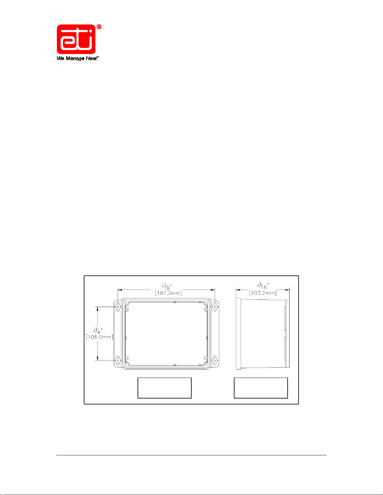
The dimensions shown in the Top View of Figure 1 are for the mounting hole
footprint location, not the overall outside dimensions of the unit, and run from
centerline to centerline of the four slotted mounting holes. The dimension shown
in the Right Side View of Figure 1 is from the bottom of the enclosure to the top
of the clear plastic lid and shows the distance the unit will protrude from the
mounting surface. For overall outside dimensions, refer to the Enclosure section
on page 26 of this manual.
Figure 1. SST–3 MOUNTING HOLE FOOTPRINT.
Top
View
Right Side
View
24494 Rev. - 04/12 (800) 234-4239 http: www.networketi.com En vironmental Technology, Inc. 7 of 28
Page 8

Adjustable Electronic Thermostat TRACON® Model SST–3 (P/N 24492)
Instruction Manual
To install the control box, perform the steps below.
1. Use the box as a template to determine the mounting hole footprint
pattern. Hold the unit up against the wall onto which it will be mounted,
with the mounting blocks against the wall, then mark the wall at the
locations of the slotted mounting holes to determine the location of the
mounting holes on the wall.
2. As desired, to hold the box in place during the installation process, you
may loosely install one or both of the top mounting bolts as the remaining
holes are marked. To ensure accurate and level installation, however, do
not fully tighten any of the mounting hardware until the locations for all the
mounting holes have been determined and marked.
3. Once the four mounting holes have been located and marked, install the
box to the wall using properly sized 5/16-inch mounting hardware. Be
sure to use mounting hardware appropriate for the job, heavy-duty and
long enough to fasten the unit securely to the mounting surface. Make
sure to use all four mounting holes. Because conduit will also be installed
to protect the cables running from the control box, install the box, but
leave the mounting hardware loose enough to work the conduit into place.
The conduit will be installed later in this process, at which time all
mounting hardware will be securely tightened.
24494 Rev. - 04/12 (800) 234-4239 http: www.networketi.com En vironmental Technology, Inc. 8 of 28
Page 9

Adjustable Electronic Thermostat TRACON® Model SST–3 (P/N 24492)
Instruction Manual
PREPARATION AND SYSTEM SET-UP
With system circuit breaker off, install the power cable, heater cable, temperature
probe, alarm relay, and conduit. Refer to Figures 2, 3, and 4, as well as Table 1.
Remove the clear plastic unit cover and face plate to access the inside of the
unit. Replace the clear plastic cover and face plate following installation.
INSTALLING THE POWER CABLE
Install the power cable as shown in Figure 2 and described in Table 1.
INSTALLING THE HEATER CABLES
Install the heater cables in accordance with National Electrical Code (NEC) and
manufacturers’ requirements, as well as other applicable codes. Properly seal
and waterproof all cable runs. Position the heater cable so it does not interfere
with the temperature probe. Never touch the ends of the yellow leads or let the
yellow leads contact each other or any component inside the control box once
power is applied. Upon conclusion of heater cable installation, perform a MegaOhm or “megger” test on the heater cables as directed by the heater cable
manufacturer. Record results on page 2 and retain for future reference.
INSTALLING THE TEMPERATURE PROBE
Install the sensor end of the temperature probe as desired for the intended
function. Route the temperature probe through conduit or through the weathertight connection port on the control. Connect both temperature probe leads to
the Temp Probe terminals on the PC board. Refer to Figure 3.
INSTALLING THE ALARM RELAY
Install the alarm relay as shown in Figures 2 and 3 and described in Table 1.
Refer especially to the paragraph on Page 11 under Figure 3. After reading the
paragraph under Figure 3, connect the alarm relay leads as desired.
INSTALLING THE CONDUIT
Only UL listed, Type 4X, raintight conduit hubs and cable glands are to be used.
The hub is to be connected to the conduit of a rigid conduit system before the
hub is connected to the enclosure. Select, measure, cut, and install the conduit
in accordance with all National Electrical Code (NEC) requirements, all local and
applicable building and electrical codes, as well as the manufacturer’s
instructions. Ensure a sealed, watertight installation.
24494 Rev. - 04/12 (800) 234-4239 http: www.networketi.com En vironmental Technology, Inc. 9 of 28
Page 10

Adjustable Electronic Thermostat TRACON® Model SST–3 (P/N 24492)
Instruction Manual
SYSTEM SCHEMATIC DIAGRAMS
Figure 2 presents a schematic diagram of the SST–3.
Input Power
Line/Black
Neutral/White
Ground/Green
200–277 VAC
50/60 Hz
30 Amp Max.
Alarm Relay
To Heater Cable
Heater Load 1/Yellow
Heater Load 2/Yellow
Heater Ground
(Shield)/Green
Temp. Probe
Alarm Relay
Leads*
Temp.
Probe
Leads
* See Page 11.
Figure 2. REPRESENTATIVE SST–3 SYSTEM SCHEMATIC.
POWER Cable (provided by customer) Size for 30 Amp maximum load
HEATER Cable (provided by customer) Size to system load
ALARM RELAY Wiring (provided by customer)* No larger than #18 AWG jacketed, 3-conductor*
TEMPERATURE PROBE Wiring #18 AWG jacketed, 2-conductor
* See Page 11.
INPUT Power
(provided by customer)
OUTPUT To Heater
(provided by customer)
OUTPUT To Alarm Relay*
(provided by customer)
* See Page 11.
Line 1 Black
Line 2 / Neutral White
Ground Green
Heater Load 1 Yellow
Heater Load 2 Yellow
Heater Ground (Shield) Green
Hook-Up Wire 1 COM
Hook-Up Wire 2 Either NC OR NO*
Wire Lead Connect To:
Table 1. CABLE RATINGS AND CONNECTIONS.
24494 Rev. - 04/12 (800) 234-4239 http: www.networketi.com En vironmental Technology, Inc. 10 of 28
Page 11

Adjustable Electronic Thermostat TRACON® Model SST–3 (P/N 24492)
Instruction Manual
Refer to Figure 3 for useful information regarding the wiring connections on the
front panel PC board.
Connect Alarm Relay
leads to these terminals.
Refer to the important
information below to
configure proper lead
connection based on
Connect Temperature
Probe leads to these
terminals. It does not
matter which lead goes
to which terminal.
Secure leads in place.
desired display mode.
Figure 3. SST–3 FRONT PANEL PC BOARD TERMINALS.
An Alarm or power off condition can be communicated in either of two ways and
it is important to make the proper alarm relay connections to achieve the desired
result. The middle terminal labeled COM (Common) will always be used.
Connect one alarm relay lead to the COM terminal. Now, if, in your system, an
external alarm light or indicator will come on to communicate an alarm or power
off condition, connect the other alarm relay lead to the NC or Normally Closed
terminal. But, if, in your system, an external alarm light or indicator will go off
to
signal an alarm or power off condition, connect the other alarm relay lead to the
NO or Normally Open terminal. Remember that when power is applied to the
unit, the Common and Normally Open contacts close to form a complete circuit.
If using a three-lead wire, it is not necessary to use all three leads when
connecting the alarm relay. Use the COM or Common terminal and either
of the
other two terminals, as desired, based on the information in this paragraph.
24494 Rev. - 04/12 (800) 234-4239 http: www.networketi.com En vironmental Technology, Inc. 11 of 28
Page 12

Adjustable Electronic Thermostat TRACON® Model SST–3 (P/N 24492)
Instruction Manual
A representative diagram of an SST–3 installation along the length of a pipe is
shown below in Figure 4. Notice how the heat tape and temperature probe do
not cross.
Figure 4. REPRESENTATIVE SST–3 PIPE INSTALLATION.
If the pipe in Figure 4 were insulated, the insulation would wrap around the pipe,
as well as the temperature probe and heat tape.
24494 Rev. - 04/12 (800) 234-4239 http: www.networketi.com En vironmental Technology, Inc. 12 of 28
Page 13

Adjustable Electronic Thermostat TRACON® Model SST–3 (P/N 24492)
Instruction Manual
POST-INSTALLATION TESTING
Installation errors cause the majority of system problems. Therefore, thoroughly
test the system before placing it into service. Simple electrical tests and visual
inspection can identify any wiring errors, as well as improper waterproofing.
Visually inspect for proper wiring and waterproofing, and make sure that all box
joints are sealed and that all wiring is properly terminated.
In performing the post-installation test procedure as described below, the heat
tape will activate, even if only for a brief time, so that system performance can be
accurately simulated. For that reason, and depending specifically on the ambient
temperature or general conditions in which the system is being installed, it is
recommended to continuously and carefully monitor the system and its
components during the entire testing process. High temperatures can damage
certain materials. Never leave the site during testing. Never leave the system
unattended during testing. If fire or smoke or an abnormal odor is observed
during testing, shut off power to the system and suspend the test.
It is the responsibility of the on-site installer to assess the overall safety concerns
at the site. To most accurately simulate and measure system performance,
leave the heat tape connected to the control during testing. Do not touch bare or
exposed metal or wiring. Even if the heaters are disconnected for testing,
voltage is still applied to the yellow leads. Therefore, never touch the ends of the
yellow leads or let the yellow leads contact each other or any component inside
the control box.
24494 Rev. - 04/12 (800) 234-4239 http: www.networketi.com En vironmental Technology, Inc. 13 of 28
Page 14

Adjustable Electronic Thermostat TRACON® Model SST–3 (P/N 24492)
Instruction Manual
CONTROL TESTING
1. Note the ambient temperature at the point of the SST–3 temperature
probe.
2. With unit power on, using the Down control button on the face of the unit,
enter a set point lower than the current ambient temperature. The green
SUPPLY LED light should be lit solid, but no other LED indicator lights
should be lit.
3. Now, press the GFEP Test/Reset button on the unit face plate. The red
GFEP LED light should flash, indicating a self-test of the GFEP circuitry,
during which time you should also hear some clicking sounds from the
relays inside the unit. The red GFEP LED indicator light should go out
once the GFEP self-test is complete.
4. Using the Up control button on the face of the unit, increase the set point
to be higher than the current ambient temperature at the point of the
temperature probe. The HEAT LED indicator light should now come on.
5. At the conclusion of this test, set the adjustable temperature setting to the
desired operational level by using the Down or Up control buttons on the
front of the unit. If the set point is above the ambient temperature, the
HEAT LED will come on until that temperature is reached, after which,
only the green SUPPLY LED should be on. The test is now complete.
24494 Rev. - 04/12 (800) 234-4239 http: www.networketi.com En vironmental Technology, Inc. 14 of 28
Page 15

Adjustable Electronic Thermostat TRACON® Model SST–3 (P/N 24492)
Instruction Manual
OPERATION
This section presents operating instructions for the unit and begins with a picture
of the front panel. Refer to Figure 5. Note the system information located on the
left side of the panel, as well as the operator controls and indicators on the right
side of the panel. The controls and indicators are explained in this section.
Operator Controls
and Indicators
Note the information
presented here.
Figure 5. THE SST–3 FRONT PANEL.
Note that because the unit has no ON/OFF power switch, power runs to the unit
as soon as facility power is connected to it. For as long as power is running to
the unit, the green SUPPLY LED will always be lit. The unit initiates a heating
cycle when the temperature probe detects a temperature of less than the set
point and remains on until a temperature 2 degrees Fahrenheit or 1 degree
Centigrade above the set point is detected.
24494 Rev. - 04/12 (800) 234-4239 http: www.networketi.com En vironmental Technology, Inc. 15 of 28
Page 16

Adjustable Electronic Thermostat TRACON® Model SST–3 (P/N 24492)
Instruction Manual
Operator controls and indicators are explained below. Refer to Figure 6.
Figure 6. SST–3 OPERATOR CONTROLS AND INDICATORS.
DISPLAY Current temperature, temperature set point, and error codes are
displayed here. Press both the Up and Down control buttons at
once for 1 second to configure. Refer to pages 18 and 19.
DOWN Press to decrease temperature set point. Hold for faster change.
UP Press to increase temperature set point. Hold for faster change.
SUPPLY The green SUPPLY LED lights up and stays lit as long as power is
running to the unit, whether it is currently in a heating cycle or not.
HEAT The yellow HEAT LED indicates a heating cycle is currently in progress.
GFEP TEST Press to reset a Ground Fault indication or to initiate a manual test of the
Ground Fault circuitry. Hold to display ground fault level.
GFEP The red GFEP LED indicates a Ground Fault condition. This LED
will flash during a GFEP test.
24494 Rev. - 04/12 (800) 234-4239 http: www.networketi.com En vironmental Technology, Inc. 16 of 28
Page 17

Adjustable Electronic Thermostat TRACON® Model SST–3 (P/N 24492)
Instruction Manual
NORMAL OPERATIONS
Under normal operations, as long as facility power is running to the unit, the
green SUPPLY LED will be lit solid and the system will provide heat, indicated by
the yellow HEAT LED, based on the thermostat set point. Any error condition
that might occur will be indicated in the display window. Error codes are
explained on page 21. The unit is designed to turn the heaters on as soon as the
temperature reading at the point of the temperature probe drops below the set
point and will keep the heaters on until the temperature reaches 2 degrees F or 1
degree C higher than the set point, at which time the heaters will shut off. Should
it be desired to change the set point, do so using the Up and Down control
buttons on the front panel of the unit as described on page 16.
THE DISPLAY WINDOW
The unit has a 3-character display window which provides useful information
regarding the function and condition of the system. During the 2-second system
initialization process, in the first half-second, the yellow Heat LED will come on
and the window will display the first character. In the second half-second of
initialization, the red GFEP LED will come on and the window will display the
second character. In the third half-second of initialization, both LEDs will come
on and the window will display the third character. Finally, in the fourth halfsecond, both LEDs shut off and the firmware version number will be displayed.
A Fahrenheit reading will be displayed as one or two digits, followed by an F. A
Centigrade reading will be displayed as one or two digits, followed by a C.
Should the temperature be above 100, as the display has but three characters, a
reading of three digits without a letter following indicates a Fahrenheit reading.
If the GFEP Test / Reset button is pressed for at least 1 second, the display will
show the current ground fault level in mA instead of the temperature.
If the temperature probe is bad, the window will display an approximation of
question marks, followed by an F or a C.
During normal operations, the display window will show the current temperature,
as well as flash with any current alarm condition, if there is one. If there are no
current alarm conditions, the display will show just the current temperature.
24494 Rev. - 04/12 (800) 234-4239 http: www.networketi.com En vironmental Technology, Inc. 17 of 28
Page 18

Adjustable Electronic Thermostat TRACON® Model SST–3 (P/N 24492)
Instruction Manual
CHANGING THE THERMOSTAT SET POINT
To set or change the thermostat set point, perform the steps below. Remember
when setting the new value that the display shows the set point degrees in the
same unit of measure (°F or °C) used to display the current temperature.
Depending on the new set point and the current temperature at the location of
the temperature probe, the Heat LED might come on until the new set point level
is reached. In addition, the LL or Low Temperature Limit error code might also
be indicated until the heaters have warmed up to within 4 degrees of the setpoint.
This is especially true during initial system start-up or if the power has been off
for some time.
1. With power running to the unit, press either the Down or the Up switch.
Now, instead of the current temperature, the window will show the current
set point and the display will flash.
2. While the display is flashing, press the Down switch to decrease the set
point or the Up switch, as desired, to increase the set point. Holding the
Down or Up switch will make the setting change faster.
3. Once the display indicates the new desired set point, release the switch.
After 3 seconds, the new value will be set, the display will stop flashing,
and the window will show the current temperature.
CHANGING THE TEMPERATURE DISPLAY MODE
The SST–3 can display temperature either as degrees Fahrenheit or as degrees
Centigrade. To toggle from either mode to the other, perform the steps below.
1. Hold down both the Up and Down switches for about one second until the
display changes. Display will show units (CEn or FAH) for Centigrade or
Fahrenheit.
2. Press the Down switch to change the display mode.
3. Press the Up switch to advance the display. Display will show FPr or nor.
(See below for Fire Protection Mode.)
4. Press the Up switch to finish.
24494 Rev. - 04/12 (800) 234-4239 http: www.networketi.com En vironmental Technology, Inc. 18 of 28
Page 19

Adjustable Electronic Thermostat TRACON® Model SST–3 (P/N 24492)
Instruction Manual
FIRE PROTECTION MODE
While in the Fire Protection Mode, in the event of a ground fault, the SST–3 will
keep the heaters going even with the ground fault. To put the system into, or to
take the system out of, the Fire Protection Mode, perform the steps below. As
you might see from the description below, the process for changing the
temperature display mode above and the process for putting the unit into or out
of the Fire Protection Mode are very similar and can both be done at the same
time. However, as either one of these actions can be taken independently,
allowing changing only one setting without changing the other, the process has
been divided into two separate procedures and presented here separately.
1. Hold down both the Up and Down switches for about one second until the
display changes. Display will show units (CEn or FAH).
2. Press the Up switch to advance. Display will show FPr for Fire Protection
Mode or nor for Normal mode.
3. Press the Down switch to change modes, as desired.
4. Press the Up switch to finish.
24494 Rev. - 04/12 (800) 234-4239 http: www.networketi.com En vironmental Technology, Inc. 19 of 28
Page 20

Adjustable Electronic Thermostat TRACON® Model SST–3 (P/N 24492)
Instruction Manual
GROUND FAULT OPERATION
USING THE GFEP TEST/RESET BUTTON
GFEP (Ground Fault Equipment Protection) circuitry is present inside this unit.
The system software checks for ground fault conditions continuously at set
intervals. If the GFEP LED is lit, press the GFEP Test/Reset button to try and
clear the situation and reset the ground fault circuitry. The GFEP will perform a
test of the ground fault circuitry, during which time, the GFEP LED will blink.
Pressing the button will not clear a “hard” fault. When the GFEP LED is lit,
unless the system has been set in Fire Protection Mode, the heaters are turned
off and will remain off until the condition is cleared. When the GFEP LED is not
lit, the operator may press the GFEP Test/Reset button, as desired, to manually
initiate a test of the GFEP circuitry. During the test, the GFEP LED will flash
rapidly for a few seconds while the unit first tests the internal circuitry and then
turns on the heaters to check for a ground fault, and will then shut off.
In the event of a ground fault condition that is not cleared by pressing the GFEP
Test/Reset Button, perform the steps below.
1. If the GFEP LED on the control box is still lit after pressing the GFEP
Test/Reset Button, remove power from the unit using the service
disconnect or the circuit breaker.
2. Perform a “megger” test of the heater cables and compare the results to
those obtained during Post-Installation Testing and recorded on page 2 of
this manual.
3. Locate and fix the problem, typically found along the run of the heat tape.
Contact the heat tape manufacturer for help troubleshooting the heat tape.
4. Restore system power. Because the presence of a ground fault condition
is stored in memory, even after repairing the ground fault condition, the
GFEP LED might still be lit following restoration of system power. In this
case, press the GFEP Test/Reset button again and the LED should go out
and normal operations can resume.
24494 Rev. - 04/12 (800) 234-4239 http: www.networketi.com En vironmental Technology, Inc. 20 of 28
Page 21

Adjustable Electronic Thermostat TRACON® Model SST–3 (P/N 24492)
Instruction Manual
ERROR CODES
Four error codes or conditions can be indicated in the display window of the
SST–3. They are explained below.
LL Low temperature limit error
This error code indicates that the temperature has been 4 degrees F (or 2
degrees C) below the set point for 30 seconds or longer. This error
condition will go away once the situation is addressed. The most likely
cause of this condition is that the heaters are broken or disconnected or,
possibly, not powerful enough if it is very cold outside. This error code
can also be indicated when the unit is first started up if the ambient
temperature is below the set point.
GFA Ground Fault alarm error
This indicates a ground fault condition external to the SST–3 unit. In this
case, check the wiring and cables leading to and from the unit. After the
problem has been located and corrected, press the GFEP Test/Reset
button to see if the situation has been resolved.
GFC Ground Fault Circuit error
This code indicates a failure of the ground fault circuitry internal to the
SST–3 unit. Press the GFEP Test/Reset button to try to clear the
situation. If pressing the GFEP Test/Reset button does not resolve the
situation, contact Environmental Technology Technical Support for
possible service options.
Prb Temperature Probe error
This error code indicates that the temperature probe is either bad or not
properly connected. Remove power from the unit and make sure the
temperature probe is properly connected to the two leads on the right side
of the PC board as shown in Figure 3 on page 11. If the temperature
probe is properly connected, then either the probe or the unit might require
service. To troubleshoot this situation, using a digital voltmeter (DVM),
check the resistance of the probe when disconnected from the circuit. The
reading should be about 100K at room temperature. If the reading is very
low (3K or less) or very high (9M or higher), the temperature probe is bad.
If the probe is OK, try substituting a 20K to 200K resistor and if the alarm
persists, the problem is likely internal to the unit.
24494 Rev. - 04/12 (800) 234-4239 http: www.networketi.com En vironmental Technology, Inc. 21 of 28
Page 22

Adjustable Electronic Thermostat TRACON® Model SST–3 (P/N 24492)
Instruction Manual
MAINTENANCE
To ensure the best function and results, it is recommended to always keep the
area around the temperature probe clean from debris and general obstructions to
maximize its sensitivity and effectiveness.
24494 Rev. - 04/12 (800) 234-4239 http: www.networketi.com En vironmental Technology, Inc. 22 of 28
Page 23

Adjustable Electronic Thermostat TRACON® Model SST–3 (P/N 24492)
Instruction Manual
USING THE JUMPER
A jumper on the PC board prevents unauthorized changing of the thermostat set
point. To initially set the thermostat set point, perform the steps below.
1. With power running to the unit, begin by changing the set point value to
the desired level. Refer to page 18 in this manual.
2. Shut off unit power.
3. Remove the unit faceplate. Retain attaching hardware.
4. Locate the jumper on the PC board. Refer to Figure 7. Position the
jumper, as desired, between Pins 1 and 2 or between Pins 2 and 3.
5. Reassemble the unit face plate onto the front of the box.
6. Restore unit power.
Position jumper between
Pins 1 and 2 or between
Pins 2 and 3, as desired.
Jumper is shown here in
the unlocked position.
Figure 7. THE JUMPER ON THE FRONT PANEL PC BOARD.
Use this procedure to set the set point for the first time. To change the set point
after the initial setting, it will be necessary to first remove power, reposition the
jumper, change the set point, then return the jumper to the locked position.
24494 Rev. - 04/12 (800) 234-4239 http: www.networketi.com En vironmental Technology, Inc. 23 of 28
Page 24

Adjustable Electronic Thermostat TRACON® Model SST–3 (P/N 24492)
Instruction Manual
TROUBLESHOOTING
If any unusual condition occurs with the unit, refer to troubleshooting charts 1 and
2 in this section. Prior to removal of any equipment, contact Environmental
Technology, Inc., Technical Support at (800) 234-4239 between 8:00 a.m. and
5:00 p.m., Eastern Time, to begin the troubleshooting process.
SST-3
PRB Fault
on display
troubleshooting
charts
LL Fault
on display
Temperature
probe
fault
Is
temperature
probe
installed
Ye s No
Possibly
faulty probe
should be
100K ohm at
70 degree F
Replace
probe
No
Install
temperature
probe
Normal operation
wait for heaters
to bring system
to operating
temperature
Re-position
Ye s
No
probe
Low
temperature
limit fault
Was the
unit just installed
or was power
off?
Temperature is
at least 4
degrees less
than set point
Is
temperature
probe installed
in proper
location
Ye s
Ye s
Are heaters
getting warm or
hot?
No
Possible heater
issue. Not
connected properly
or heater failure
TROUBLESHOOTING FLOWCHART 1.
24494 Rev. - 04/12 (800) 234-4239 http: www.networketi.com En vironmental Technology, Inc. 24 of 28
Page 25

Adjustable Electronic Thermostat TRACON® Model SST–3 (P/N 24492)
Instruction Manual
SST-3
GFA Fault
on display
troubleshooting
charts
GFC Fault
on display
Ground fault
indicated
Will it
reset with
button
No
Turn off power,
remove heater
load, and turn
on power
Will it
reset with
button
No
Ye s
Temporary
fault
Ye s
Heater tape
faulty. Check
and repair or
replace
Ground fault
circuit test failed
SST-3 possibly
damaged.
Repair or
replace
SST-3 possibly
damaged.
Repair or
replace
TROUBLESHOOTING FLOWCHART 2.
24494 Rev. - 04/12 (800) 234-4239 http: www.networketi.com En vironmental Technology, Inc. 25 of 28
Page 26

Adjustable Electronic Thermostat TRACON® Model SST–3 (P/N 24492)
Instruction Manual
SPECIFICATIONS
GENERAL
Areas of Use Nonhazardous
Approvals
UL Listed to UL 1053 Ground-Fault
Sensing and Relaying Equipment
ENCLOSURE
Protection IP 66 NEMA 4X
Dimensions
Material Polycarbonate
Cover Attachment Polycarbonate cover, machine screws
Weight 3 pounds (1.4kg)
Mounting Wall Mount
Cable Entries
5 1/4” (L) x 8” (W) x 4 1/16” (H)
133.2mm (L) x 203.2mm (W) x 103.2mm (H)
4: incoming power cable @ 1.05”; (27mm)
outgoing heater cable @ 1.05”; (27mm)
outgoing alarm relay @ 1.05”; (27mm)
incoming temperature probe @ 0.67” (17mm)
FRONT PANEL INTERFACE
SUPPLY (green): Power on
Status Indicator
HEAT (yellow): Heating cycle in progress
GFEP (red): Ground fault condition
GFEP (red, rapid flashing): GFEP test in progress
24494 Rev. - 04/12 (800) 234-4239 http: www.networketi.com En vironmental Technology, Inc. 26 of 28
Page 27

Adjustable Electronic Thermostat TRACON® Model SST–3 (P/N 24492)
Instruction Manual
CONTROL
Supply Voltage 200 - 277 VAC; 50/60 Hz
Heater
200 - 277 VAC;
30 Amp Maximum Resistive Load
GROUND FAULT EQUIPMENT PROTECTION
Set Point 30 mA
GFEP verified before contactors operate; GFEP
Automatic Self-Test
GFEP Manual Test/Reset GFEP Test/Reset switch on front panel
tests on start-up of power and automatically
every 24 hours
WIRE AND CABLE RATINGS
Power Cable Size for heater load (30 Amp maximum)
No larger than #18 AWG jacketed, 3-conductor
Alarm Relay Wiring
Heater Cable Size for maximum heater load
Temperature Sensor Wiring #18 AWG jacketed, 2-conductor
(Only two leads will be used; refer to Figure 3
on page 11.)
ENVIRONMENTAL
Operating Temperature −31°F to +130°F (−35°C to 55°C)
Storage Temperature −67°F to +167°F (−55°C to 75°C)
THERMOSTAT SET POINT
SST–3 Set Point Range +34°F to +150°F (1°C to 65°C)
24494 Rev. - 04/12 (800) 234-4239 http: www.networketi.com En vironmental Technology, Inc. 27 of 28
Page 28

Adjustable Electronic Thermostat TRACON® Model SST–3 (P/N 24492)
Instruction Manual
ORDERING INFORMATION
Order Number Description
24492 TRACON Model SST–3 Adjustable Electronic Thermostat
24493 SST–3 Data Sheet
24497 SST–3 Installation Sheet
24494 SST–3 Instruction Manual (this document)
23731 Accessory Kit
19272 Temperature Probe Assembly
QUESTIONS AND COMMENTS
For technical help, questions, or comments concerning this product or any of Environmental
Technology, Inc., products, contact the Customer Service Department between 8:00 a.m. and 5:00
p.m. Eastern Time at:
Voice: (800) 234-4239 (USA and Canada) or (574) 233-1202 (elsewhere)
Fax: (888) 234-4238 (USA and Canada) or (574) 233-2152 (elsewhere)
DISCLAIMER
Environmental Technology, Inc. makes no representations or warranties, either expressed or implied, with respect to
the contents of this publication or the products that it describes, and specifically disclaims any implied warranties of
merchantability or fitness for any particular purpose. Environmental Technology, Inc. reserves the right to revise
this publication and to make changes and improvements to the products described in this publication without the
obligation of Environmental Technology, Inc. to notify any person or organization of such revisions, changes or
improvements.
No part of this manual may be reproduced or translated in any form or by any means, electronic or mechanical
including photocopying and recording, for any purpose without the express written consent of Environmental
Technology, Inc.
The ETI logo, We Manage Heat, and TRACON are registered trademarks of Environmental Technology, Inc.
SST is a trademark of Environmental Technology, Inc.
Copyright
24494 Rev. - 04/12 (800) 234-4239 http: www.networketi.com En vironmental Technology, Inc. 28 of 28
E-mail: info@networketi.com
©
2012 Environmental Technology, Inc. All rights reserved.
 Loading...