

Page 1
SRK10 Splice and Tee Kit with End Seal
Installation, Operation and Maintenance Instructions
IMPORTANT: Save These Instructions!
DESCRIPTION
The SRK10 Splice and Tee kits are to
be used with King SR heating cables.
Carefully follow these instructions. Do
not use other materials or alternate
splicing methods which may damage
the heating cable and create an
electrical hazard, risk of fire, or poor
performance.
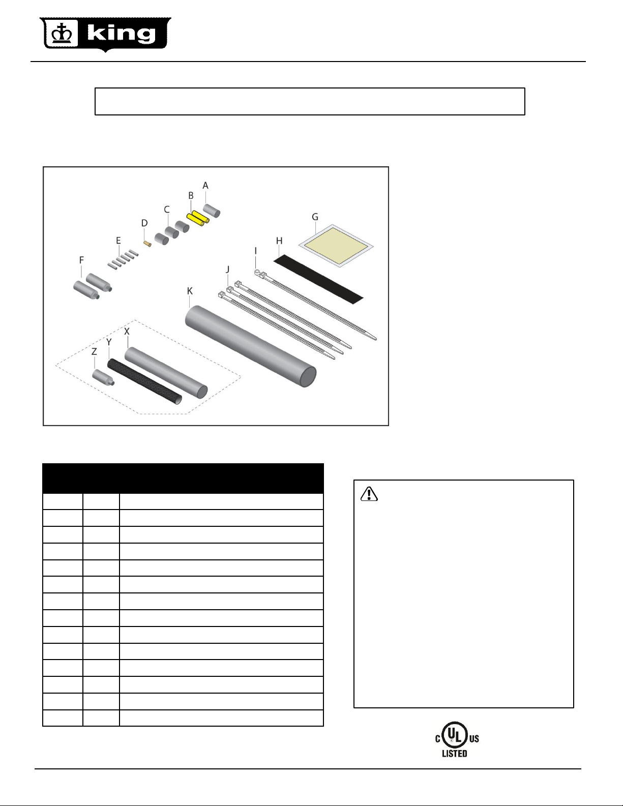
SRK10 SPLICE AND TEE KIT
The SRK10 kit is to be used with King
SR heating cables to make a splice, tee
connection and one end seal.
CAUTION: Charring or burning the
heat shrink tubing can produce fumes
that may cause eye, skin, nose and
throat irritation. Use adequate
ventilation during installation and avoid
overheating the heat shrink tubing.
TOOLS REQUIRED: utility knife, cross
cutters, needle nose pliers, crimping
tool, heat gun.
Item Qty Description
A 1
B 2
C 3
D 1
E 6
F 2
G 5
H 1
I 1
J 3
K 1
X 1
Y 1
Z 1
Black heat shrink tube for ground
Insulated buss wire crimp connectors
Black heat shrink tube (1/2” dia. x 1” length)
Un-insulated ground crimp connector
Black heat shrink tube (1/8” dia. x 1” length)
Heat shrink cap (1/2” dia. x 2” length)
Mastic strips (1” width x 1-1/2” length)
Black cloth tape (1” width x 6” length)
Cable tie with mounting hole
Cable ties
Black heat shrink tube (1” dia. x 8” length)
Black heat shrink tube (3/4” dia. x 5” length)
Woven braid sleeve ( ½” dia. x 4” length)
Black heat shrink cap ( ½” dia. x 1-1/4” length)
WARNING: ELECTRIC SHOCK HAZARD
Disconnect all power before installing or servicing
the heating cable and accessories. SR heating
cable must be grounded properly in accordance
with the National Electrical Code (NEC). Failure to
comply can result in personal injury or property
damage. Only a qualified licensed electrical
contractor shall install and service of SR heating
cable and accessories, otherwise the warranty is
voided.
Note:·All electrical wiring, including Ground Fault
Circuit Interrupters (GFCI), must be done
according to the NEC and local codes by a
qualified installer. Article 426 of ANSI/NFPA 70 of
National Electrical Code (NEC section 62 of
CAN/CSA-C22.1, Canadian Electrical Code, Part I
(CEC) governs the installation of this heat systems
www.king-electric.com 1
Rev 9.15.12
Page 2
WARNING:
The SRK10 kit components are electrical devices and they must be installed correctly to ensure proper operation and to prevent
shock or fire. Carefully follow all of the installation instructions and read these important warnings.
1. Heating cables must be installed in compliance with the national electric code (NEC) in addition to state, provincial and local
codes. Check with your local inspector for specific code requirements (or regulations or standards) in your area.
2. To minimize the danger of fire from electrical arcing if the heating cable is damaged or improperly installed ground fault
equipment protection (GFEP) must be used on each heating cable branch circuit. Arcing may not be stopped by conventional
circuit protection.
3. Bus wires will short if they make contact each other, keep bus wire separated.
4. Keep ends of heating cable and kit components dry before and during installation.
5. The black heating cable core is conductive and can short. It must be properly insulated and kept dry.
6. UL listing approvals and performance are based on the use of the specified components in this kit only. Do not substituted
parts or use vinyl electrical tape.
7. Damaged heating cable can cause arcing or fire. Do not energize damaged heating cable. Repair or replace damaged heating
cable prior to applying power.
8. Do not twist cables during installation or embed in thermal insulation.
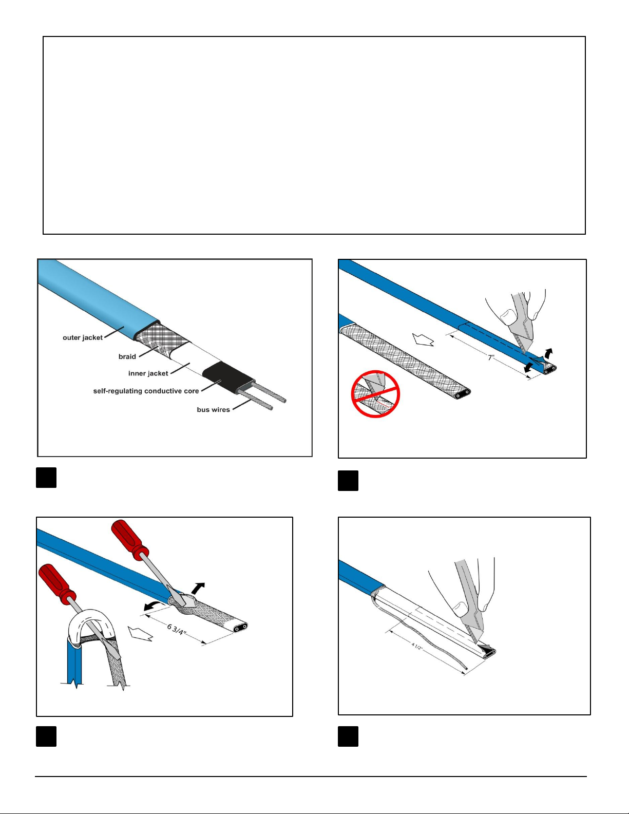
The SR heating cable is comprised of several layers as shown
above, use the illustration to gain a clear understanding of the
1
cable components.
Cut the braid and push it back to loosen it as shown.
Bend the cable and gently pull it through the braid.
Lightly score completely around and then down
outer jacket a distance of 7”. Do not cut braid or inner
2
jacket. Bend heating cable to break jacket at score,
then peel off outer jacket!.
Twist and position the braid to one side of heating
4 3
cable and then cut the insulating jacket back 4-1/2”.
Lightly score the inner insulating jacket and then bend
the cable to break the jacket and peel it off.
www.king-electric.com 2
Rev 9.15.12
Page 3
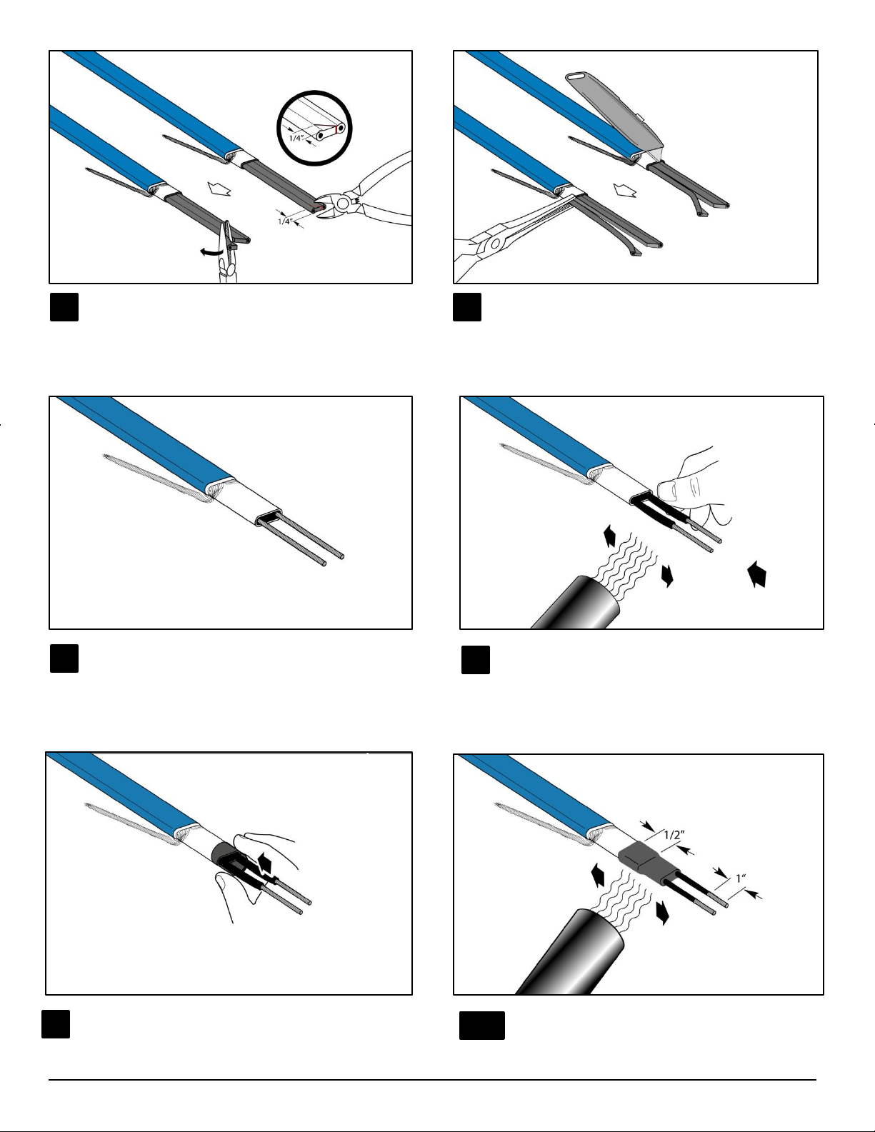
Notch the conductive core at the end and twist it back
5 6
to peel the bus wires from the core.
Score between the bus wires and bend the core to
break it free and peel the core material away from the
bus wires.
Cut and remove the remaining center core, leaving the
7
bare conductors.
Center the 1/2” x 1” heat shrink tube over the cable core
9
and bus wires as shown.
Slide the 1/8” dis. X 1” heat shrink tube over the bus wires.
Apply heat to shrink the tubes, approximately 2 minutes at
8
600ºF (315ºC). Keep tubes up against the core while heat
shrinking.
10
Heat evenly for approximately 3 minutes at 600ºF
(315ºC) until it shrinks completely.
www.king-electric.com 3
Rev 9.15.12
Page 4

Immediately pinch the tube with pliers between the
11
bus wires while it is still hot and hold for 10 seconds.
Make sure the heat shrink tube is completely sealed
between the bus wires with no visible gap.
Remove release paper from mastic strip and wrap the
12
mastic around the outer jacket as shown. Do this to all
the cables to be spliced.
Wrap a second piece of mastic around the end of the
13
cable as shown. Pinch the center of the mastic to seal
the conductive core.
Twist the braided ground pigtails together.
15
Carefully align the heating cable sections and place
14
them together, press mastic strips firmly together.
Fasten with a cable ties at each of the two positions
shown (10-3/4” and 7-3/4”).
Place the un-insulated connector provided on the
16
ground wires.
www.king-electric.com 4
Rev 9.15.12
Page 5

Crimp with the un-insulated connector.
17
Trim off excess braid.
18
Slide the 1/2” dia. X 1” heat shrink tube over the un-
19
insulated ground crimp. Apply heat evenly for
approximately 3 minutes to shrink the tube.
Fold the crimped braid back against the heating
21 22
cables. Wrap the black cloth tape evenly around crimp
and heating cables. Cover crimp completely.
20
Immediately after shrinking, pinch the end of the tube
with flat nose pliers for approximately 10 seconds until
the end stays sealed.
Twist the bus wires together, make sure not to cross
the wires as this will cause a direct short, keep the left
side wires and right side wires separate. Slide the
insulated crimps onto the bus wires.
www.king-electric.com 5
Rev 9.15.12
Page 6

Use a crimping tool and crimp each connector, be sure
23
to apply enough force to make a solid connection. Pull
on connector to make sure it is on tight, a loose
connection will cause excessive heat and fail.
Slide the heat shrink cap over each set of crimped wire.
24
Heat from the end of the cap evenly until it shrinks and
adhesive flows out the end. Total heating time should be
about 3 minutes at 752ºF (400ºC)..
Remove the release paper from the mastic strips and
25
wrap one strip using the width side (not length) around
the each cap. Stretch the mastic tape if necessary to
make sure the width wraps around the cap completely.
Start heating at far end from the crimped wire work toward
27 28
the open end. Keep heating after tube has shrunk, to melt
adhesive and mastic inside the tube.
Important: additional heating is required after the tube is
shrunk to melt the mastic and adhesive inside. Ensure
the mastic melted to fill the gaps at the end of the cable.
26
Slide the 1” diameter by 8” long heat shrink tube over
the entire piece of cable. Place the edge of the tube at
the edge of the mastic.
Shrink the tube completely at the starting point, keep
heating until the ring of mastic and adhesive appears.
Then work the heat gun toward the open end. Total
heating time should be about 5 minutes at 752ºF
(400ºC).
www.king-electric.com 6
Rev 9.15.12
Page 7

Immediately after shrinking, pinch the end of the tube
29
with flat nose pliers until the end stays sealed; this will
take about10 seconds.
Important: If the width of flat-nose pliers is not wide
enough to pinch the entire end of the tube, then pinch
several times to seal the end completely.
.
When splicing two cables together, fold the cable over as
30
shown and fasten with a cable tie.
31
For downspout applications secure the supply cable to the downspout hanger (SRK15)
with a cable tie as shown. Then clamp the next cable onto the downspout hanger
using another cable tie. The third cable will continue down the gutter.
Warranty Information:
King Electrical Mfg. Company will repair or replace, without charge to the original owner, any heating cable found to be defective or malfunctioning within the 2 year warranty.
In Case of Product Failure: Contact King Electrical Mfg. Co. at 800.603.5464. The owner will be required to provide, within the designated warranty period, the following
information: model number, date of purchase, and a complete description of the problem encountered with product. Upon receipt of the aforementioned, the company will
reply to the owner within a period not to exceed fifteen (15) working days, and will provide the action to be taken by owner. Terms: This warranty requires the owner or his
agent install the equipment in accordance with the National Electrical Code, any other applicable heating or electrical codes and the manufacturer's installation instructions. It
further requires that reasonable and necessary maintenance be performed on the unit. Failure of proper maintenance by owner will void the warranty in its entirety. The
company is not liable for any actions it deems to be abuse or misuse of the product. The customer shall be responsible for all costs incurred in the removal or reinstallation of
products, including, but not limited to, labor costs, and shipping costs incurred to return products to King Manufacturing. At their discretion, King Manufacturing will decide to
either repair or replace the product, with no charge to the owner, with return freight paid by King. The Company shall not be liable for consequential damages arising with
respect to the product, whether based upon negligence, tort, strict liability or contract. No other written or oral warranty applies, nor any warranties by Representatives,
Dealers, Employees of King or any other person. King Manufacturing can be contacted by phone at 206.762.0400, fax 206.763.7738 or website www.king‐electric.com.The
company's minimum liability shall not in any case exceed the list price for the product claimed to be defective.
www.king-electric.com 7
Rev 9.15.12
Page 8

SRK10 Splice and Tee Kit with End Seal
www.king-electric.com 8
Rev 9.15.12
 Loading...