

Page 1
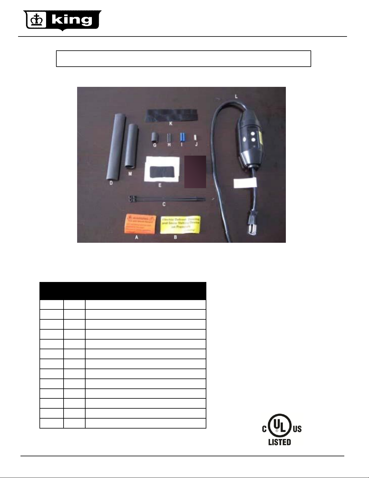
SRK08 GFEP 120V Plug-in Power Connection Kit
Item
Qty
Description
A
2
B
2
C
2
D
1
E
2
G
1
H
2
I
2
J
1
K
2
X
1
Y
1
Z
1
Installation, Operation and Maintenance Instructions
IMPORTANT: Save These Instructions!
www.king-electric.com 1
Warning labels for pipe trace
Warning labels for gutter ice melt.
Cable ties
Black heat shrink tube (1” dia. x 8” length)
Mastic strips (1” width x 1-1/2” length)
Black heat shrink tube (1/2” dia. x 1” length)
Black heat shrink tube (1/8” dia. x 1” length)
Insulated bus wire crimp connectors
Un-insulated ground braid crimp connector
Black cloth tape (1” width x 6” length)
Black heat shrink tube (3/4” dia. x 5” length)
Woven braid sleeve ( ½” dia. x 4” length)
Black heat shrink cap ( ½” dia. x 1-1/4” length)
Rev 11.04.12
DESCRIPTION:
SR self-regulating heating cables
are designed for a variety of pipe
freeze protection as well as roof
and gutter deicing applications.
The heat output (wattage)
increases and decreases based on
the temperature, so the cable
adjusts automatically to varying
climate conditions. This unique
feature ensures maximum energy
efficiency by increasing the heat
output only when it is needed. No
thermostat is required.
Page 2
DESCRIPTION
The SRK08 GEFP plug-in power connection kit is to be used with King SR self regulating heating cables only. The kits are
not approved to be used with other brands of heating cable. The kit contains enough material for making one 120 volt plug-in
power connection and one end seal. King SR cables are approved for both pipe freeze protection and roof and gutter deicing
applications. The kit is to be used with copper wire only, do not use aluminum power supply wires
ADDITIONAL MATERIALS REQUIRED
• UL Listed weatherproof junction box when used outdoors with a weatherproof cover for the plug.
• The junction box requires a 120 volt receptacle for the GFEP device to plug into.
• For heating cable with no outer-jacket, a metallic junction box must be used to ensure proper grounding.
• The application may require additional accessories; for example, SRK03 application tape for pipe applications or SRK13
roof clips and/or SRK15 downspout hangers for roof and gutter deicing.
TOOLS REQUIRED
• Adjustable wrench or pliers, needle nose pliers, diagonal cutters, utility knife, screwdriver, propane torch or heat gun,
crimp tool.
WARNING
Fire and shock hazard. Improperly installed heating cable can cause electrical shock, arcing, and fire.
Carefully follow all the instructions provided read the cautions and warnings.
1.Heating cables must be installed in compliance with the national electric code (NEC) in addition to state, provincial and local
codes. Check with your local inspector for specific code requirements (or regulations or standards) in your area.
2.Save these instructions and transfer them to future owner(s).
3.Never install on pipes that could potentially exceed 150º F, (65º C).
4.Do not substitute components or use or use vinyl electrical tape.
5. Not for use with indoor pipes. Cable should not run through the building walls, ceilings or floors.
6.For safety, King recommends that all heating cables are placed on a Ground Fault Equipment Protection (GFEP) circuit.
Consult your local electrical inspector to determine the specific requirements in your area.
7.The black heating core is conductive and can short. It must be properly insulated with heat shrink tubing.
8.Keep components and heating cable ends dry during installation.
9.Damaged bus wires can overheat or cause an electrical short. Do not energize cable if the bus wires are damaged.
10.Do not break the braid or bus wire strands when stripping the jacket or conductive core.
11.Bus wires will short if they come in contact with each other. Never spice the bus wires together, they must remain
separate.
12. Heat-damaged components can short, the use a heat gun is preferred. Use a torch with a soft, yellow ,low-heat flame, not
a high heat blue focused flame. Keep the flame moving to avoid overheating, blistering, or charring the heat-shrinkable
tubes. Avoid heating other components and replace any heat damaged parts prior to energizing the cable.
13.Use only fire-resistant insulation materials such as fiberglass wrap.
14. Do not twist he cable during installation.
15.De-energize all supply power circuits before installation or servicing.
16. Do not embedded the heating cable.
17.Post warning labels supplied with the cable at the power supply and along the pipe on the outside of the insulation.
18.Do not bend the cable to less than a 1/2” radius.
19.Do not Install cable on shingle roofs in freezing temperatures; as this may cause damage to the shingles.
20.Cables are intended for freeze protection of water pipes only. Not intended for use with other liquids or hazardous
materials.
21. Install cable in accessible areas only.
Caution: Charring or burning the heat-shrinkable tubes in this kit can produce fumes that may cause eye, shin, nose, and
throat irritation. Ensure proper ventilation during installation to minimize this health risk.
Important: For the warranty to be valid, installer must comply with all requirements outlined in these guidelines. All design
information provide her is based upon a standard installation with heating cable fastened to an insulated pipe.
Electrical codes: Article 427 of the National Electrical Code and Section 62 of CAN/CSA-C22.1, Canadian Electrical Code
govern the installation of King SR heating cable for pipe freeze protection.
www.king-electric.com 2
Rev 11.04.12
Page 3
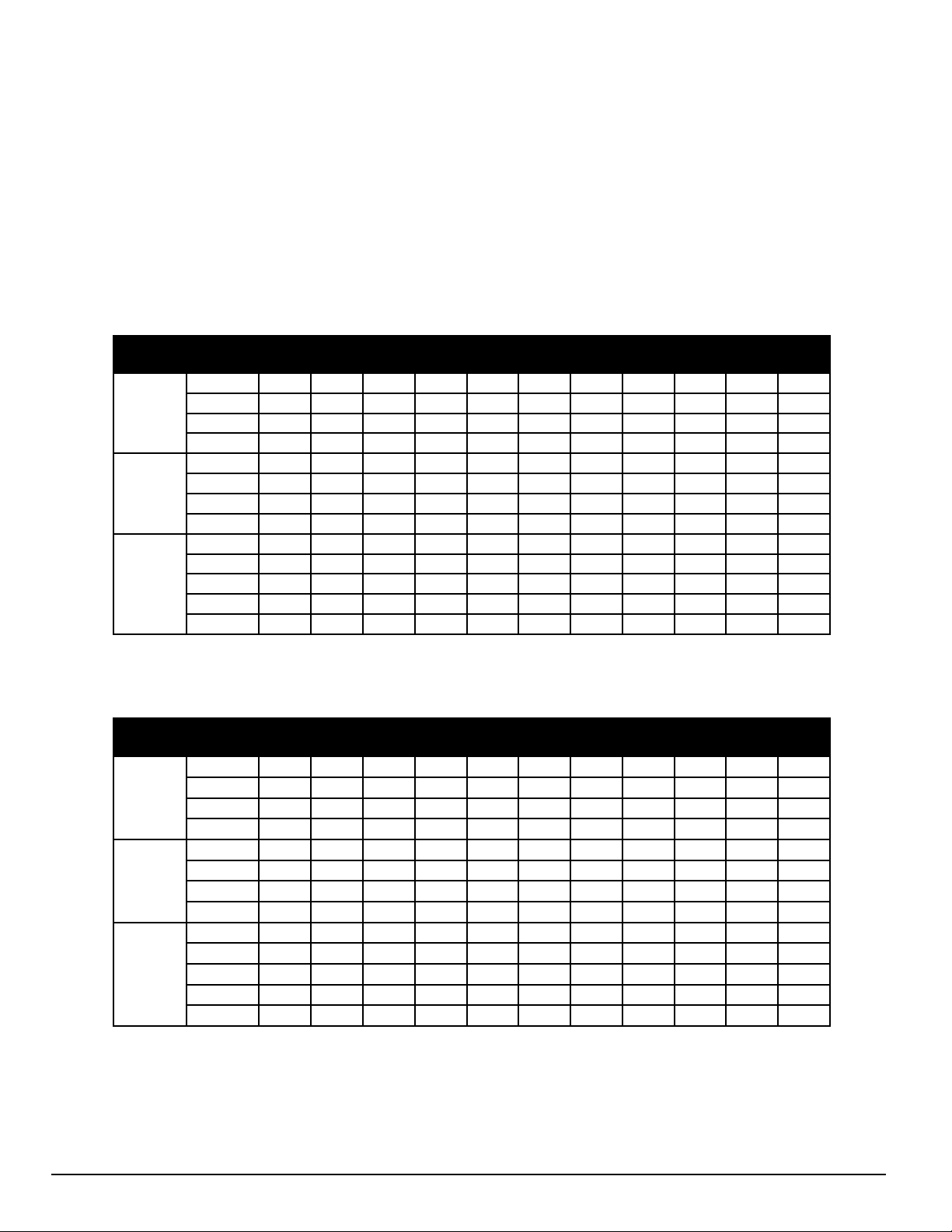
SR Heating Cable Selection and Design
Lowest
Air Temp.
Insulation
Thickness
1/2”
3/4”
1”
1-1/4”
1-1/2”
2”
2-1/2”
3”
4”
6”
8”
0ºF
(-18ºC)
1/2”
3
3 3 3 5 5 5 5 8 8
10
1”
3 3 3 3 3 3 3 5 5 8 8
1-1/2”
3 3 3 3 3 3 3 3 5 5 5
2”
3 3 3 3 3 3 3 3 3 5 5
-20ºF
(-29ºC)
1/2”
3 5 5 5 5 5 8
8
10
10
*
1”
3 3 3 3 3 5 5 5 8
8
10
1-1/2”
3 3 3 3 3 3 3 5 5 8 8
2”
3 3 3 3 3 3 3 3 5 5 8
-40ºF
(-30ºC)
1/2”
5 5 5 5 8
8
10
(2) 8
(2) 8
(2) 10
*
1”
3 3 3 5 5 5 8 8 8
10
(2) 8
1-1/2”
3 3 3 3 3 5 5 5 8
8
10
2”
3 3 3 3 3 3 3 5 5 8 8
3”
3 3 3 3 3 3 3 3 3 5 5
Lowest
Air Temp.
Insulation
Thickness
1/2”
3/4”
1”
1-1/4”
1-1/2”
2”
2-1/2”
3”
4”
6”
8”
0ºF
(-18ºC)
1/2”
3 5 5 5 8 8 8
10
(2) 8
(2) 10
*
1”
3 3 3 5 5 5 5 5 5 8 8
1-1/2”
3 3 3 3 3 3 5 8 8
8
10
2”
3 3 3 3 3 3 3 5 5 8 8
-20ºF
(-29ºC)
1/2”
5 5 8
8
10
10
(2) 8
(2) 8
(2) 10
*
*
1”
3 3 5 5 5 8 8
8
10
(2) 8
(2) 10
1-1/2”
5 5 5 5 5 5 5 8 8
10
(2) 8
2”
3 3 3 3 3 5 5 5 8
8
10
-40ºF
(-30ºC)
1/2”
8 8 8
8
10
10
(2) 8
(2) 10
* * *
1”
5 5 5 8 8
8
10
10
(2) 8
*
*
1-1/2”
5 5 5 5 5 8 8
8
10
(2) 8
(2) 10
2”
5 5 5 5 5 5 5 8 8
10
(2) 8
3”
3 3 5 5 5 5 5 5 5
8
10
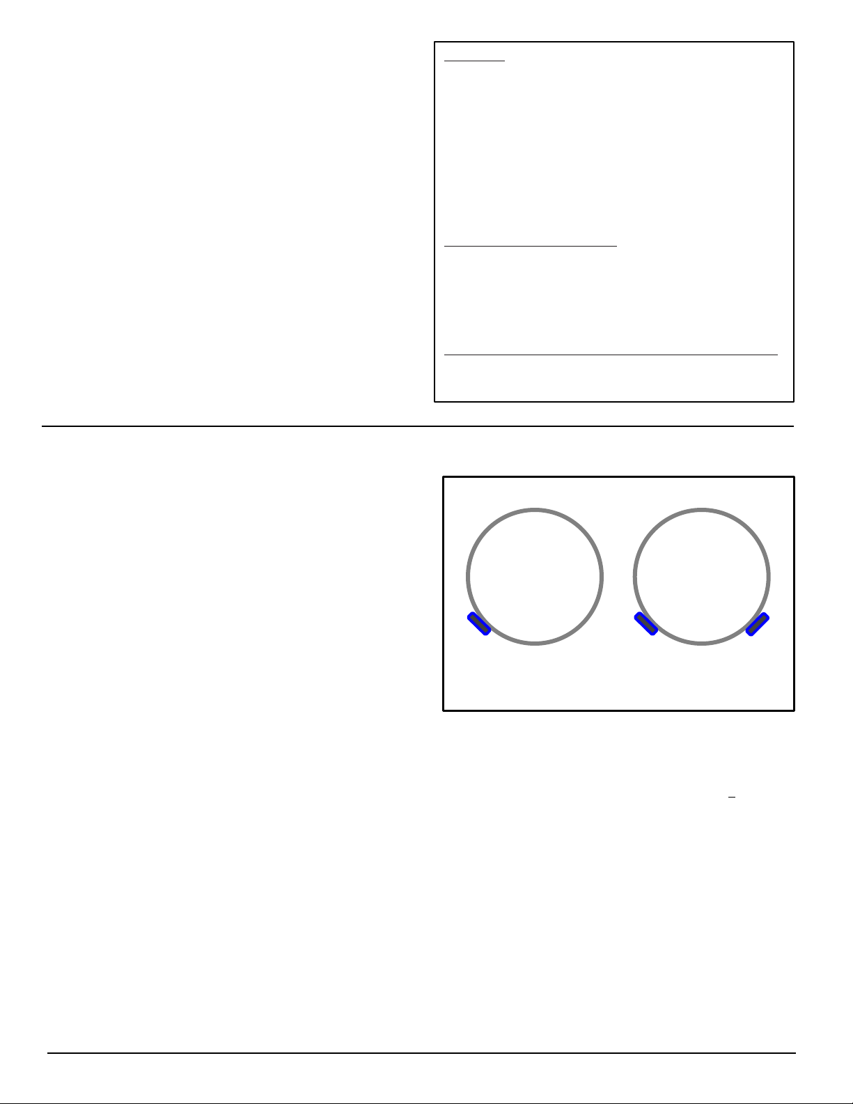
Use table 1 to select the heating cable size for insulated metal pipes and use table 2 to select heating cables for
insulated plastic pipes. Read across the table to find the pipe size, then drop down the column to the row
corresponding to the lowest design air temperature column for the application and chose the thickness of the
insulation that will be used. The cell that intersects will give the power (watts/ft.) of the cable required and it may also
have a number (2) in the cell which represents using 2 cables. Run the cable straight along the bottom of the pipe. If
two cables are required, attach them at the 4 and 8 o’clock positions as shown in figure 1 page 4. Spiral tracing the
cable is not recommended as it is labor intensive.
Table 1' – SR cable selection for metal pipes (w/ft.)
Table 2' – SR cable selection for plastic pipes (w/ft.)
' The tables are based on using fiberglass insulation or equivalent while maintaining a 40ºF (4ºC) pipe
temperature with a 10% safety factor and 20 mph wind speed.
* Contact King for the proper cable selection
www.king-electric.com 3
Rev 11.04.12
Page 4
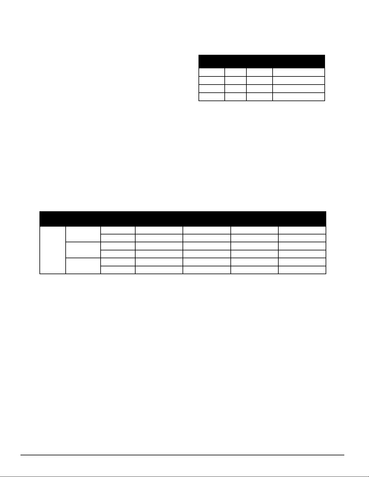
Model
Volts
Watt/ft
Maximum
Single Run Length
SR123
120V
3 w/ft
325 ft. (99M)
SR125
120V
5 w/ft
270 ft. (82M)
SR128
120V
8 w/ft
210 ft. (64M)
SR1210
120V
10 w/ft
180 ft. (55M)
Volts
Start up
Temp.
Circuit
Breaker*
SR123
3w/ft.
SR125
5w/ft.
SR128
8w/ft.
SR1210
10w/ft.
120 V
50ºF
(10ºC)
15 Amp
325 ft. (99M)
225 ft. (69M)
145 ft. (44M)
115 ft. (35M)
20 Amp
435 ft. (133M)
270 ft. (82M)
195 ft. (59M)
150 ft. (46M)
0ºF
(-18ºC)
15 Amp
230 ft. (70M)
155 ft. (47M)
100 ft. (30M)
85 ft. (26M)
20 Amp
305 ft. (93M)
205 ft. (72M)
130 ft. (40M)
110 ft. (34M)
-20ºF
(-29ºC)
15 Amp
205 ft. (63M)
135 ft. (41M)
90 ft. (27M)
75 ft. (23M)
20 Amp
275 ft. (84M)
180 ft. (55M)
115 ft (35M)
100 ft. (30M)
Circuit Breaker Protection and Cable Length Design for Pipe Freeze Protection
Table 3: Maximum Single Cable Length
The maximum length of a single cable run is noted in Table 3
and cannot be exceeded. If the application requires a longer
cable run, then multiple cables and additional power circuits
must be used.
Circuit protection depends on the length of cable required
and the start-up temperature since the cable will draw more
power (wattage) when cold. Multiple cables can be run from
a single power circuit up to a maximum combined length as
noted in Table 5. Larger amperage circuits breakers can
handle longer combined cable lengths, but the maximum
length for a single cable run does not change. The NEC
requires the use of ground fault protection breakers for
heating cable.
Table 5: Circuit Protection Per Combined Cable Length for Pipe Freeze Protection
www.king-electric.com 4
Rev 11.04.12
Page 5
SR Heating Cable Selection and
Design (continued)
CALCULATE THE TOTAL HEATING CABLE LENGTH
Cable length = A+B+C+D+E+F
A Pipe length x number of cables
B 4 ft. x number of valves
C 2 ft. x number of flanges, supports, etc.
D 1 ft. for each power connection
E 2 ft. for each splice connection
F 3 ft. for each tee connection
= Total heating cable length (ft)
MAXIMUM CIRCUIT LENGTH ALLOWED
Ensure that your circuits do not exceed the maximum
circuit length listed in Table 3, page 4. If necessary,
use additional shorter circuits.
EXAMPLE
Pipe size: 2” metal pipe
Lowest air temp: -20°F
Insulation thickness: 1”
Cable selection: (1) 5w/ft. (From table 1, pg 3)
Pipe length: 80 ft.
Valves: 2
Pipe supports: 12
Power connections: 1
Splice connections: 1
HEATING CABLE REQUIRED
A Pipe length x number of cables 80 ft. x 1 = 80 ft.
B 4 ft. x number of valves 4 ft. x 2 = 8 ft.
C 2 ft. x number of flanges, supports, etc. 2 ft. x 12 = 24 ft.
D 1 ft. for each power connection 1 ft. x 1 = 1 ft.
E 2 ft. for each splice connection. 1 ft. x 1 = 1 ft.
F 3 ft. for each tee connection 3 ft. x 0 = 0 ft.
= Total heating cable length (ft) 114 ft.
Heating Cable Installation
GENERAL NOTES
1. Verify that the heating cable is the correct length, wattage
and voltage prior to installation.
2. All welding, hydrostatic testing, and painting of the pipe
should be completed before the heating cable installation.
3. The piping system must be inspected to ensure that it is
clean, dry and has no sharp or jagged edges that could
potentially damage the heating cable.
4. Do not install the heat tracing before completion of the entire
piping system.
5. The cables must be installed a minimum of 10 inches away
from wood or any other combustible materials.
6. The minimum cable bending radius is 1/2 inch.
STEP 1: PREPARE FOR INSTALLATION
1. Store the heating cable in a clean, dry place.
2. Perform a pressure test on the pipe prior to cable installation.
3. Remove any sharp surfaces on the pipe that could potentially
damage the outer jacket of the heating cable.
4. Walk the pipe system and plan the routing of the heating
cable on the pipe.
STEP2: CUT THE HEATING CABLE TO LENGTH
1. Cut the heating cable to length required. This can be done
before or after the cable is attached to the pipe.
2. Leave a minimum of 1 foot extra heating cable for connection
to the supply power.
3. For splice and tee connections, leave a minimum of 1 foot for
each section of heating cable.
4. King SR heating cable can to length without affecting its heat
output per foot.
5. When splicing and terminating be sure to protect the cable
ends from moisture, contaminants and mechanical damage.
Single Cable
Double Cable
Figure 1: Cable Placement on Pipe
STEP 3: ATTACH THE CABLE TO THE PIPE
1. Verify pipe to be traced is completely dry.
2. For straight tracing, install the heating cable on a the lower
half of the pipe; for example, in the 4 o’clock or 8 o’clock
position as shown in Figure 1.
3. Install the extra heating cable as required for valves,
flanges, etc.
4. Spiral tracing is not recommended as it is labor intensive.
5. If applying spiral tracing, begin by suspending a loop
of cable every 10 feet as shown. To determine the loop
length, divide the length of pipe length and multiply by
10.
6. Fasten the heating cable to the pipe at 2 foot intervals
using SRK03 fiberglass tape or nylon cable ties. Do not
use vinyl electrical tape, duct tape, metal bands or wire.
7. If there is excess cable at the end of the pipe, double
remaining cable back along the pipe.
www.king-electric.com 5
Rev 11.04.12
Page 6
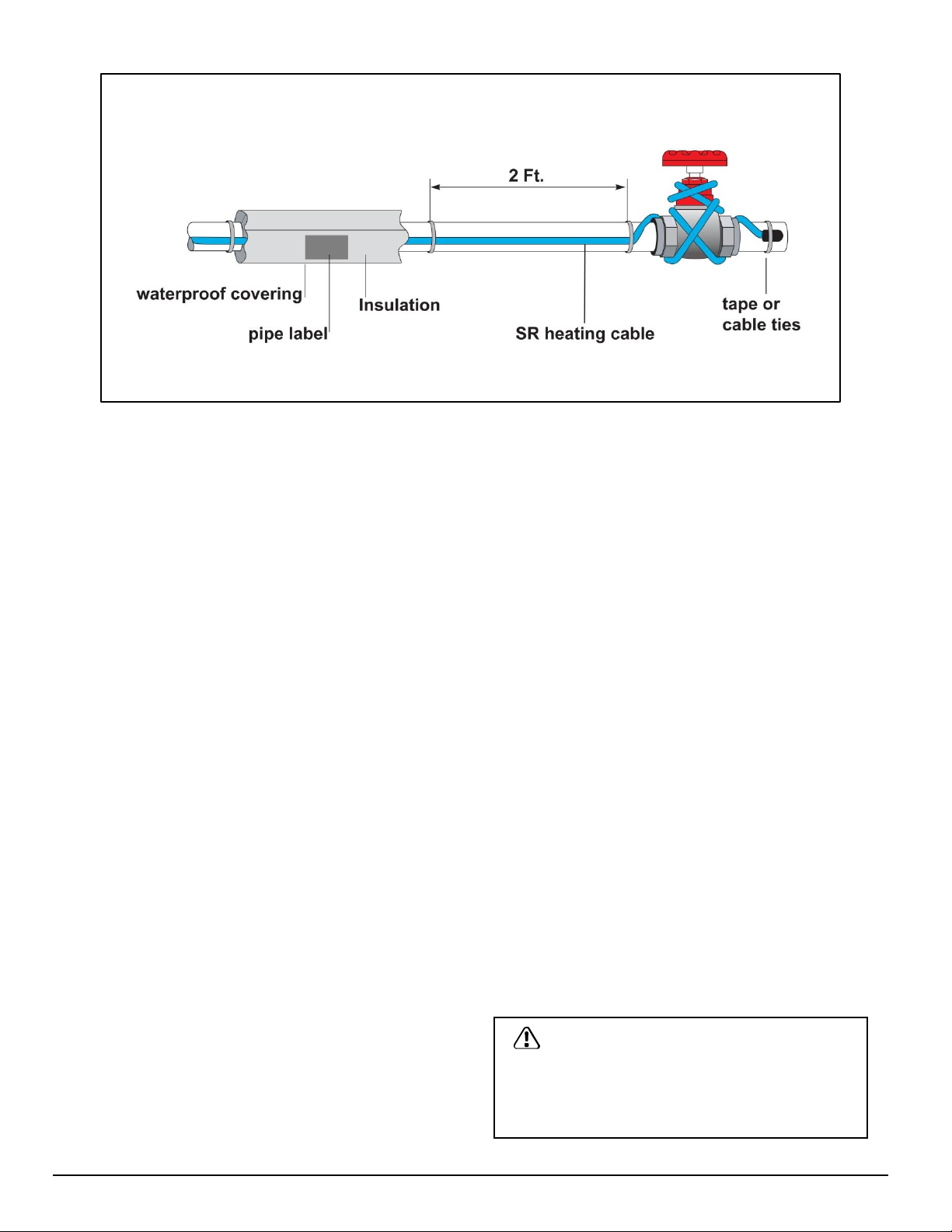
Figure 2: SR Cable installation for Pipe Freeze Protection
Heating Cable Installation (continued)
STEP 4: INSTALL ACCESSORIES KITS
1. Install heating cable end seals, splices, tees, and
power connection prior to energizing cable.
2. Use only the SR00 power connection kit, SRK10
splice and tee kit, SRK08 GFEP power connection kit
and SRK 12 end seal kit.
STEP 5: CHECK FOR PROPER INSTALLATION
1. Before installing the thermal insulation, inspect the
heating cable to verify damage did not incur during
installation including any thermal damage or other
disturbance which may have occurred if exposed to
a excessive heat.
2. Visually inspect all power connections, end seals,
splices and tee connections.
STEP 6: INSTALL THE THERMAL INSULATION
1. The heat trace system requires weatherproofed
thermal insulation installed as shown in Figure 32.
2. A minimum of at least 1/2" of preformed foam or
equivalent thermal insulation must be used on all
piping, including valves, joints, and wall
penetrations.
3. Install the insulation on the piping as soon as
possible to minimize the potential for mechanical
damage after installation.
.
STEP 7: FASTEN LABELS
1. Place caution labels so they are visible on the
outside of the thermal insulation at 10 ft intervals on
alternating sides of the pipe to indicate the presence
of the electric heating cable system. Additional labels
and fiberglass tape are available in SRK03 kit.
STEP 8: STARTING THE HEATING CABLE SYSTEM
1. Test per the “cable testing and maintenance”
section.
2. Check the circuit breaker to verify there is power to
the cable.
3. Check standing water in the pipe after one hour, it
should feel warm.
STEP 9: CABLE TESTING AND MAINTENANCE
1. Using a 2500-volts DC megohmmeter, check the
resistance between both of the power prongs on the
plug and the ground prong after installing the heating
cable. Minimum reading should be 1000 megohms.
2. Record the original values for each circuit, and
compare subsequent readings taken during regular
maintenance to the original values.
3. If the readings fall below 1000 megohms, replace with a
new cable or repair with the proper SRK accessory kit.
WARNING
Fire and shock hazard. Damaged heating cable can
cause electrical shock, arcing, and fire. Do not
energize a damaged heating cable. Immediately
replace the cable or repair it with the proper SRK
accessory kit.
www.king-electric.com 6
Rev 11.04.12
Page 7

SR Heating Cable Design for Roof and Gutter Applications
GENERAL INFORMATION
1. SR cable is designed to remove ice, not accumulated
snow.
2. SR cable will not keep snow or ice from falling off of the
roof. Snow fences or snow guards should be used to
eliminate snow movement.
3. SR heating cables may be used on:
- Roofs made from all types of roofing materials, such as
shake, shingle, rubber, tar, wood, metal, and plastic.
- Gutters made from standard materials, such as metal
and plastic.
- Downspouts made from standard materials, such as metal
and plastic.
4. Do not install the heating cable underneath any roof
covering.
5. Install only in accessible locations; do not install behind
walls or where the cable would be hidden.
6. Do not run the heating cable through walls, ceilings, or
floors.
7. Connect only to ground-fault protected circuit breakers or
outlets that have been installed in accordance with all
national and local codes and standards and that are
protected from rain and other water sources such as
melting ice water.
8. Do not exceed the amp rating of the over current
protection device.
Selecting the Required Heating Cable Length for Roof and Gutter Deicing
CALCULATION FOR HEATING CABLE LENGTH:
Use the formula below to determine the amount of heating
cable required.
Total heating cable length = A+B+C+D+E+F+G
A (Roof edge) × (heating cable multiplier)
B (Roof edge x 0.5)
C (Total gutter length)
D (Total downspout length + 1 ft)
E (1 ft for each power connection)
F (2 ft for each splice)
G (3 ft for each tee connection)
= Total heating cable length required
Example:
1. Roof edge = 48 ft
2. Eave overhang = 1 ft (Refer to Table 6)
3. Gutter = 48 ft
4. Downspout = 22 ft
5. Power connection = 2 each
6. Splice = 3 each
Heating Cable Required:
A Roof edge: 48 ft × 2.8 (From table 6) = 134.4 ft
B Roof extension*: 48 ft x 0.5 = 24.0 ft
C Roof gutter: 48 ft = 48.0 ft
D Downspout: 22 ft + 1 ft = 23.0 ft
E Power Connection: 2 x 1 ft = 3.0 ft
F Splice Connection: 3 x 2 ft = 6.0 ft
G Tee Connection: 0 x 3 ft = 0.0 ft
Total heating cable length required: = 238.4 ft
*Roof extension is the length of cable required to prevent ice
dams between the roof edge and the gutter. When there are
no gutters present it forms a drip loop to prevent ice dams at
the roof edge.
Eave
Overhang
None 2.0 2.5 2.0
12” 2.8 2.8 2.4
24” 3.8 3.6 2.9
36” 4.8 4.3 3.6
Standard
Roof
Metal Roof
18” Seam
Table 6: Heating Cable Multiplier
Use the number in the table and multiply it by the length of the roof edge.
CALCULATIONS FOR GUTTERS, DOWNSPOUT AND VALLEYS:
1. For standard non-metal roofs, add 1 foot of heating cable for
each foot of gutter.
2. Add 1 foot of heating cable per foot of downspout.
3. If the downspout is in the middle of the run, loop the cable
down and back up. Double the length of the downspout for
determining the length of cable to install.
4. For valleys, run the heating cable two thirds of the way up and
down the valley. Add this additional length to the overall cable
needed.
5. For gutters 6 inches wide use two cable runs.
DESIGN NOTES:
1. In-line splices and tee splices should be avoided where
possible.
2. Heating cable in downspouts should be looped and extend
below the frost line if tied into a drainage system.
3. End terminations should not be located in an area where
moisture is present. End terminations should not be located at
the lowest point of downspouts.
4. ·For roof drains leading into a heated area, a loop of heating
cable should be installed to a depth of 3 ft.
Metal Roof
24” Seam
www.king-electric.com 7
Rev 11.04.12
Page 8

·
Figure 3: Shake and Shingle Roof Attachment
Eave
overhang
None 24” 18” 2.0 ft
12” 24” 18” 2.8 ft
24” 24” 30” 3.8 ft
36” 24” 42” 4.8 ft
Tracing
width
Tracing
height
Cable/roof
edge
Table 7: Tracing Heights for Shake and Shingle Roof
The last column gives the amount of cable required per foot of
roof edge for standard shake and shingle roof (table 7) or a
metal seam roof (table 8).
Figure 4: Metal Roof Attachment
Eave
overhang
None 18” 18” 2.5 ft
12” 18” 24” 2.8 ft
24” 18” 36” 3.6 ft
36” 18” 48” 4.3 ft
None 24” 18” 2.0 ft
12” 24” 24” 2.4 ft
24” 24” 36” 2.9 ft
36” 24” 48” 3.6 ft
Tracing
width
Tracing
height
Cable/roof
edge
Table 8:Tracing Heights for Metal Seam Roof
Heating Cable Installation
PREPARE FOR INSTALLATION
1.Store the heating cable in a clean, dry place.
2. Inspect for any mechanical damage prior to installation.
3. Warranty is void if non-King accessories are used. King
approved accessories include:
- SRK00 Power connection kit
- SRK03 Fiberglass tape and labels
- SRK08 GFEP plug-in connection kit
- SRK10 Splice and tee kit
- SRK12 End seal kit
-SRK13 Roof clips
- SRK15 Downspout hanger bracket
4. Gutters and downspouts must be free of leaves and other
debris.
5.Carefully plan the routing of the heating cable for roof and
gutter deicing.
6. Inspected the mounting surface for sharp edges and remove
as anything that could damage the cable.
www.king-electric.com 8
Rev 11.04.12
STEP1: CUT THE HEATING CABLE TO LENGTH
1. Cut the heating cable to length required. This can be done
before or after it is installed. Leave a minimum of 1 foot extra
heating cable for power connection. For splice connections
leave a minimum of 2 ft, and 3 ft for each tee connection.
STEP 2: ATTACH THE HEATING CABLE ON ROOFS
1.Loosely loop the heating cable on the roof at the overhang
area. Pull the bottom of each heating cable loop over the roof
edge and, using a UV-resistant cable tie as. Connect the
bottom of each loop to the cable running in the gutter. This will
ensure a drainage channel for the melting ice to drain off the
roof and into the gutter and downspout. The cable in the gutter
should remain against the bottom of the gutter as shown in
Figure 3 (Standard Roof) and Figure 4 (Metal Roof).
2.Extend the top of each heating cable loop beyond where the
wall joins the roof.
3.Use SRK13 roof clips to route heating cable up and down the
edge of the roof according to the tracing height noted in the
tables above and shown in Figures 6 and 7. Route the heating
cable in such a way as to prevent abrasion to the cable jacket.
Page 9

Figure 5: Roof Clip, Standard Shake Roof
STEP 2 (continued)
4. One SRK13 kit contains 25 roof clips for approximately 17
linear feet of the roof edge.
5. Roof clips may be attached to a shake or shingle roof
using nails or screws. Roof clips may be attached to a
metal roof using nails, screws, or adhesive. Reseal the
nail or screw holes if necessary before installing heating
cable in the clips. See SRK13 installation instructions for
additional details on mounting roof clips.
6. A barrier (snow fence) can be placed on the roof above
the heating cable. This prevents damage to the cable and
keeps the roof brackets from tearing loose during ice
slides. The heating cable can be attached to the barrier
with UV-resistant cable ties, instead of using roof clips.
The use of other materials, such as wire, may cause
damage to the heating cable and will void the warranty.
STEP 3: ATTACH THE HEATING CABLE ON VALLEYS
1.Trace two-thirds of the way up each valley with a double
run of heating cable as shown in Figure 7.
STEP 4: INSTALLING THE CABLE IN GUTTERS AND
DOWNSPOUTS
1.Run the heating cable in the gutters and into downspouts,
end the cable in a loop at the bottom of the downspout and
then run the cable back up the downspout using a tie
wraps to fasten it as shown in Figure 8. Permanent
attachment of the cable to the gutter bottom is not
necessary.
2.Use the King SRK15 downspout brackets at the transition
of the gutter and downspout to protect the cable from
fraying. Refer to the SRK15 installation instructions for
more details.
3. Route and secure cable with care to avoid mechanical
damage during installation or maintenance from such
things as ladders, etc.
Figure 6: Roof Clip, Metal Roof
Figure 7: Roof Valleys
Figure 8: SRK15 Downspout Bracket
www.king-electric.com 9
Rev 11.04.12
Page 10

STEP 5: TERMINATING DOWNSPOUTS
1. The preferred method of installation is to run the heating
cable into the downspouts, ending the cable in a loop at
the bottom of the downspout and then run the cable
back up the downspout into the gutter . This way there is
no end seal in the downspout. For single cable runs in
downspouts with an end seal use a tie wrap to fasten it
as shown in Figure 9. Do not leave the end of the
heating cable pointing down at the end of the
downspout, double back as shown. Never create a
situation where an end seal is positioned to be a drip
point at the end of a cable run.
STEP 6: INSTALL END SEALS, SPLICES, TEES, AND
POWER CONNECTION KITS
1.If installing a GFEP device on the cable the carefully follow
the SRK08 installation instructions.
2.Use only listed weatherproof junction boxes approved for
wet location when installing SR cable.
3.·Use only listed watertight construction or enclosures,
Type 3, 3s 4, 4X ,6,or 6P.
4.·When possible, all power connection boxes should be
located in a protected area (such as under eaves) and
entry should be at the bottom of the box. In all case, a drip
loop should be installed, do not let an end seal or splice or
tee connection become a drip point.
STEP 7: ATTACH THE WARNING LABLES
1. Two warning labels are provided with the SR cable kit to
indicate the presence of electric deicing and snow-melting
equipment on the premises. One label should be attached
at the electrical outlet cover and the other label must be
posted at the fuse or circuit breaker panel feeding the
outlet circuit. Labels must be clearly visible.
STEP 8: CHECK AND INSPECT THE INSTALLATION
1. Prior to powering the deicing cable into the outlet, check
the entire length of the cable for mechanical damage such
as nicks and cuts in the outer insulation and any potential
thermal damaged which may have occurred if cable was
exposed to excessive heat.
2. Use a megohmmeter to test each circuit according to the
instructions in the “Heating Cable Testing and
Maintenance” section of these instructions.
3. Junction boxes should be inspected for water and for
evidence of water damage. If moisture is present, the box
should be restored to a dry condition and the cause of the
water intrusion should be investigated and eliminated.
4. Test the ground fault circuit to be sure it is functioning
properly. If malfunctioning, replace prior to energizing the
system. Functionality of over-current protection devices
such as circuit breakers or fuses should be checked as
well.
Figure 9: Downspout Termination
GROUND FAULT PROTECTION
National electrical codes require ground-fault equipment
protection on each heating cable branch circuit. To reduce
the risk of fire caused by damage or improper installation,
circuit breakers with a 30-mA trip level are required.
Alternative designs providing comparable levels of groundfault protection may also be acceptable.
HEATING CABLE TESTING AND MAINTENANCE
1.Make sure that gutter and downspouts are free of leaves
and other debris annually prior to the winter season.
2. Using a 2500-Vdc megohmmeter, check the resistance
between both of the power prongs on the plug and the
ground prong after installing the heating cable. Minimum
reading should be 1000 megohms.
3. Record the original values for each circuit, and compare
subsequent readings taken during regular maintenance
to the original values.
4. If the readings fall below 1000 megohms, replace the
cable with a new unit. Do not attempt to repair the cable.
5. Caution:·Maintenance and repair of the heating cable
system should only be preformed by a qualified electrician..
WARNING
Fire and shock hazard. Damaged heating cable can
cause electrical shock, arcing, and fire. Do not attempt
to repair or energize damaged heating cable. If
damaged, immediately repair or it and replace with a
new cable.
www.king-electric.com 10
Rev 11.04.12
Page 11

Model
Volts
Output at
32ºF (0ºC)
Maximum
Single Run
Length
SR123
120V
5.0 w/ft
273 ft. (83M)
SR125
120V
8.0 w/ft
216 ft. (66M)
SR128
120V
12.1 w/ft
171 ft. (52M)
SR1210
120V
14.8 w/ft
152 ft. (46M)
Cable
Volts
Start up
Temp
15 Amp
(ft.)
20 Amp
(ft.)
30 Amp
(ft.)
40 Amp
(ft.)
SR123
120V
32ºF (0ºC)
273
273
273
273
20ºF (-7ºC)
254
268
273
273
0ºF (-18ºC)
213
255
273
273
-20ºF (-29ºC)
182
248
273
273
SR125
120V
32ºF (0ºC)
188
216
216
216
20ºF (-7ºC)
166
216
216
216
0ºF (-18ºC)
144
193
216
216
-20ºF (-29ºC)
127
173
216
216
SR128
120V
32ºF (0ºC)
126
168
171
171
20ºF (-7ºC)
118
157
171
171
0ºF (-18ºC)
103
136
171
171
-20ºF (-29ºC)
92
123
168
171
SR1210
120V
32ºF (0ºC)
102
143
152
152
20ºF (-7ºC)
97
126
152
152
0ºF (-18ºC)
88
117
152
152
-20ºF (-29ºC)
76
104
152
152
Circuit Breaker Protection and Cable Length Design for Deicing
Table 9: Circuit Breaker Protection for Deicing Table 10: Technical Data Ratings
Technical Data Table
Maximum operating temp. 150°F (65°C)
Maximum exposure temp. 185°F (85°C)
Minimum installation temp. 0°F (-18°C)
Minimum bending radius 1”, (24 mm)
Dimensions
Service voltage
Table 11: Maximum Single Run Length
Technical Data Notes:
1. The maximum single cable run is the longest length of heating cable before there is a
significant voltage drop which will lower the wattage rating of the cable.
2. The circuit breaker sizes in Table 9 are per the National Electric Code (NEC).
3. The NEC requires ground-fault equipment protection (GFEP) for fixed outdoor deicing
equipment. All electrical connections should be made by a licensed electrician.
.496” x .236”
(12.6mm x 6mm)
110-120V,
208V-277V
www.king-electric.com 11
Rev 11.04.12
Page 12

The SR heating cable is comprised of several layers as shown
above, use the illustration to gain a clear understanding of the cable
components.
Slide the 1”dia. x 8” long and the 1” dia. x 5” long
black heat shrink tubes over the stripped end of the
1
cord.
Cut the braid and push it back to loosen it as shown.
Bend the cable and gently pull it through the braid.
Lightly score completely around and then down
outer jacket a distance of 7”. Do not cut braid or inner
2
jacket. Bend heating cable to break jacket at score,
then peel off outer jacket!.
Twist and position the braid to one side of heating
4 3
cable and then cut the insulating jacket back 4-1/2”.
Lightly score the inner insulating jacket and then bend
the cable to break the jacket and peel it off.
www.king-electric.com 12
Rev 11.04.12
Page 13

Notch the conductive core at the end and twist it back
5 6
to peel the bus wires from the core.
Score between the bus wires and bend the core to
break it free and peel the core material away from the
bus wires.
Cut and remove the remaining center core, leaving the
7
bare conductors.
Center the 1/2” x 1” heat shrink tube over the cable core
9
and bus wires as shown.
Slide the 1/8” dis. X 1” heat shrink tube over the bus wires.
Apply heat to shrink the tubes, approximately 2 minutes at
8
600ºF (315ºC). Keep tubes up against the core while heat
shrinking.
10
Heat evenly for approximately 3 minutes at 600ºF
(315ºC) until it shrinks completely.
www.king-electric.com 13
Rev 11.04.12
Page 14

11
Immediately pinch the tube with pliers between the
bus wires while it is still hot and hold for 10 seconds.
Make sure the heat shrink tube is completely sealed
between the bus wires with no visible gap.
12
Use the insulated connectors and crimp tool to
connect black and white wires to bus wires of heating
cable. Polarity does not matter.
13
15
Remove the release paper from mastic strips, wrap
one strip of mastic around the black wire at the end of
the splice to make a water tight seal, then repeat this
procedure for the white wire.
Center the 5” heat shrink tube over the splice, make sure
it extends over the end of each heating cable and the
cord. Start at the middle and work toward each end.
Keep heating after tube has shrunk, to melt mastic and
adhesive inside tube.
14
16
Squeeze the two mastic together to create a water tight
seal.
Make sure the adhesive appears at both ends.
Immediately after shrinking, pinch one end of the tube
and then the other end with needle nose pliers until
the ends stay sealed. Hold for 10 seconds per end.
www.king-electric.com 14
Rev 11.04.12
Page 15

17
19
Use the un-insulated connector with a crimp tool to
connect braid to green ground wire. Wrap the
connector with the black cloth tape. Cover crimped
connector completely.
Center the 8” heat shrink tube over the entire splice,
make sure it extends over the end heating cable and
the cord. Start at the middle and work toward each
end.
18
20
Cover crimped connector completely.
Shrink the tubing completely.
Completed splice
www.king-electric.com 15
Rev 11.04.12
Page 16

Pipe freeze protection
Cable
ties
To prevent damage to the GFEP device and to provide strain
relief to the cord, use cable ties to secure the device to the
wall near the receptacle. Be careful not to damage either the
cord or the ground-fault unit.
Note: Pipe must be fully insulated.
Pipe freeze protection
Cord label
Plug the heating cable into a 15 amp, 120-Vac grounded
outlet.
Make sure that:
– The cord label is visible.
– The indicator light on the ground-fault equipment
protection device is on.
– The receptacle is properly weatherproofed (if outdoors).
– The ground-fault equipment protection device and the
power connection splice will not be submerged.
Roof and gutter de-icing
Cable
ties
Roof and gutter de-icing
Deicing
label
Cord label
To prevent damage to the ground-fault equipment
protection device and to provide strain relief, use clamp
ties to secure the device to the wall near the receptacle.
Be careful not to damage either the cord or the groundfault unit.
The SRK08 should be mounted high up, away from
persons to prevent damage to the unit and the risk of
shock
www.king-electric.com 16
Rev 11.04.12
Plug the heating cable into a 15 amp, 120-Vac grounded
outlet approved for wet locations.
Make sure that:
– The cord label is visible.
– The indicator light on the ground-fault equipment
protection device is on.
– The receptacle is properly weatherproofed.
– The ground-fault equipment protection device and power
connection splice will not be submerged.
Page 17

SRK12 End Seal Kit
Item
Qty
Description
A
1
B
1
C
1
Installation, Operation and Maintenance Instructions
IMPORTANT: Save These Instructions!
DESCRIPTION:
SR self-regulating heating cables are designed for
a variety of pipe freeze protection as well as roof
and gutter deicing applications. The heat output
(wattage) increases and decreases based on the
temperature, so the cable adjusts automatically to
varying climate conditions. This unique feature
ensures maximum energy efficiency by increasing
the heat output only when it is needed. No
thermostat is required.
WARNING: ELECTRIC SHOCK HAZARD
Disconnect all power before installing or servicing
the heating cable and accessories. SR heating
cable must be grounded properly in accordance
with the National Electrical Code (NEC). Failure to
comply can result in personal injury or property
damage. Only a qualified licensed electrical
contractor shall install and service of SR heating
cable and accessories, otherwise the warranty is
voided.
Note:·All electrical wiring, including Ground Fault
Circuit Interrupters (GFCI), must be done according
to the NEC and local codes by a qualified installer.
Black heat shrink tube (3/4” dia. x 5” length)
Woven braid sleeve ( ½” dia. x 4” length)
Black heat shrink cap ( ½” dia. x 1-1/4” length)
Article 426 of ANSI/NFPA 70 of National Electrical
Code (NEC section 62 of CAN/CSA-C22.1,
Canadian Electrical Code, Part I(CEC) governs the
installation of this heat systems
1 2
CAUTION: When removing the outer
jacket, be careful not to damage the braid
or the inner core insulation.
www.king-electric.com 17
Score the outer jacket 2” from the end
of the cable.
Remove the outer jacket to expose
the braid.
Rev 11.04.12
Push the braid back off the end of the
3
cable.
WARNING: ELECTRIC SHOCK HAZARD
Do not connect the bus wires together.
Keep braid out of heat shrink cap.
Page 18

Push back the braid and cut 3/4” off
4 5
the end of the cable..
Push back the braid and slide the heat
shrink cap over the end of the cable..
Apply heat evenly until the cap shrinks
6
around the cable.
Pull the braid back over the end cap and
7
twist the braid end together.
Apply heat evenly to the heat shrink
10
tube unit it shrinks around the cable
Slide the 4” woven braid sleeve
8
over the cable, allowing 1/2” to
extend past the end.
While the shrink tubing is still hot,
11 12
gently squeeze the end with pliers
and hold it until it has cooled.
Slide the 5” heat shrink tube over the
9
woven braid, allowing it to extend 1/2”
past the end of the woven sleeve just
applied.
The end must remain sealed after
the pliers are removed. If the tube
does not remain sealed, then repeat
steps 7 and 8.
Warranty Information:
King Electrical Mfg. Company will repair or replace, without charge to the original owner, any heating cable found to be defective or malfunctioning within the 2 year warranty.
In Case of Product Failure: Contact King Electrical Mfg. Co. at 800.603.5464. The owner will be required to provide, within the designated warranty period, the following
information: model number, date of purchase, and a complete description of the problem encountered with product. Upon receipt of the aforementioned, the company will
reply to the owner within a period not to exceed fifteen (15) working days, and will provide the action to be taken by owner. Terms: This warranty requires the owner or his
agent install the equipment in accordance with the National Electrical Code, any other applicable heating or electrical codes and the manufacturer's installation instructions. It
further requires that reasonable and necessary maintenance be performed on the unit. Failure of proper maintenance by owner will void the warranty in its entirety. The
company is not liable for any actions it deems to be abuse or misuse of the product. The customer shall be responsible for all costs incurred in the removal or reinstallation of
products, including, but not limited to, labor costs, and shipping costs incurred to return products to King Manufacturing. At their discretion, King Manufacturing will decide to
either repair or replace the product, with no charge to the owner, with return freight paid by King. The Company shall not be liable for consequential damages arising with
respect to the product, whether based upon negligence, tort, strict liability or contract. No other written or oral warranty applies, nor any warranties by Representatives,
Dealers, Employees of King or any other person. King Manufacturing can be contacted by phone at 206.762.0400, fax 206.763.7738 or website www.king‐electric.com.The
company's minimum liability shall not in any case exceed the list price for the product claimed to be defective.
www.king-electric.com 18
Rev 11.04.12
 Loading...