

Page 1
SAVE THESE INSTRUCTIONS
INSTALLATION AND MAINTENANCE
SAFTEY INFORMATION
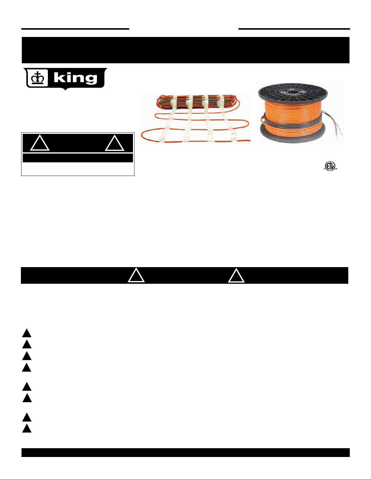
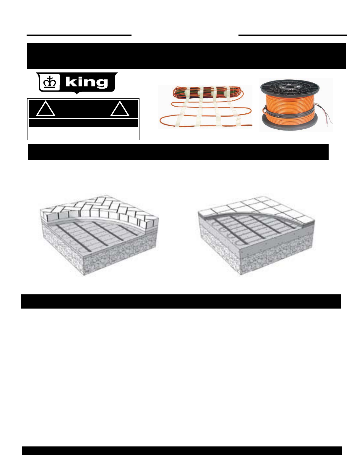
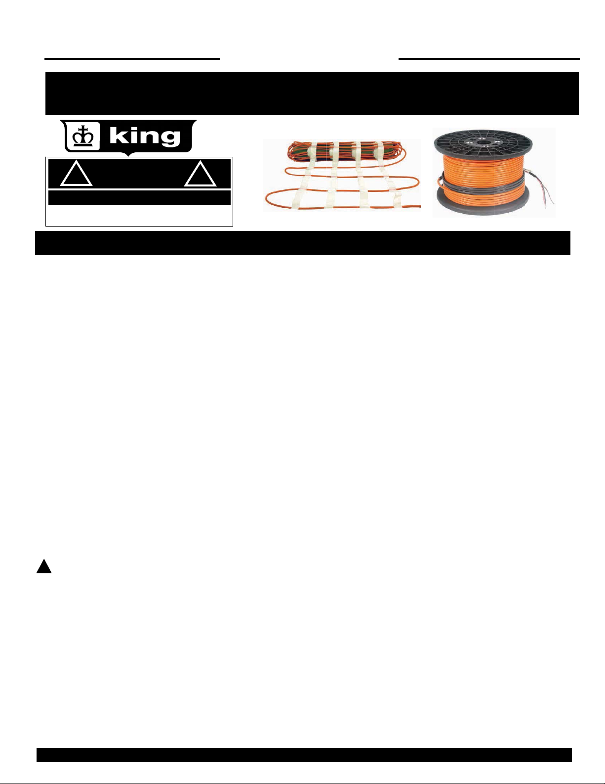
SC/SCM Snow Melt
Cable and Mats
!
ELECTRIC SHOCK OR FIRE HAZARD
READ ALL WIRE SIZING, VOLTAGE REQUIREMENTS AND SAFETY DATA TO
AVOID PROPERTY DAMAGE AND PERSONAL INJURY
King’s Snow Melt Systems are great solutions to stay ahead of the snow and ice when winter arrives. On-demand snow melt improves the
safety of driveways, sidewalks, stairs and other outdoor foot-traffic areas, keeping them free from the dangers of ice.
SCM Series Mats, provide pre-fabricated mats at 50W/SqFt (3” spacing) that can be rolled out prior to the concrete slab being poured.
Whether you are heating concrete, asphalt or pavers the SCM will keep your area clear and safe to walk on.
SC Series Cable offers a custom in-concrete layout solution to snow and ice build-up, and can be installed to fit any individual application.
Cable can be spaced to allow between 35W/SqFt – 50W/SqFt (3” or 4”spacing) depending on the application.
DANGER
!
!
READ CAREFULLY
performed by qualified personnel, in accordance with local codes and standards.
Read these important warnings and all installation instructions prior to installation. Failure to do so can result in fire, electrical shock, property
damage, personal injury and/or death.
WARNING
!
WARNING
!
WARNING
!
WARNING
!
WARNING
!
WARNING
!
WARNING
!
WARNING
!
KING ELECTRIC MFG CO · 9131 10TH AVENUE SOUTH · SEATTLE, WA 98108 · PH:206 762 0400 · FAX: 206 763 7738 · www.king-electric.com
-
It is important to read these instructions carefully before installing the SC Snow Melt System. Installation must be
Installation must be performed by qualified personnel, in accordance with local codes and standards.
For outdoor installation only.
Never cut the heating cable.
Extreme care must be used to ensure the SC cables or SCM mats are not damaged when using sharp tools, wheelbarrows, heavy machinery
and paving equipment, shovels rakes, or other equipment. Avoid walking on the cable/mats during installation.
It is not recommended to install the SC cables or SCM mats with a controller that does not contain an integrated temperature limiter.
The SC cable or SCM mats must be embedded in mortar or a mortar mixture, concrete, sand or a similar material; The heating cable connection and at least 1’ of the power lead must be embedded in the paved surface.
NEVER pull any of the heating cable or factory splices into any conduit. Only the remaining power lead should be run through the conduit.
The power lead may be extended or cut shorter if required, but never removed from the heating cable. (Continued on page 2)
WARNING
!
1
Page 2
SAVE THESE INSTRUCTIONS
SAFTEY INFORMATION
!
ELECTRIC SHOCK OR FIRE HAZARD
READ ALL WIRE SIZING, VOLTAGE REQUIREMENTS AND SAFETY DATA TO
AVOID PROPERTY DAMAGE AND PERSONAL INJURY
DANGER
!
!
WARNING
!
WARNING
!
WARNING
!
WARNING
!
Do not install SC cable in such a way that the heating cables touch, cross, overlap, or place heating cable closer than 2 inches from another
heating cable power lead cable, underground cable or piping to keep from overheating them.
Always keep ends of the power leads dry before and during installation.
Remember to always measure, verify and record the actual resistance throughout the installation process:
1. Prior to installation
2. After installation
3. While Puring Concrete
4. Final Commissioning
Record these values on the SC Cable / SCM Mat Testing Log on page 19 , failure to do so will void the warranty.
Measure the resistance between the two live conductors as well as the resistance between each conductor and the ground
wire.
WARNING CONTINUED
!
!
WARNING
!
WARNING
!
WARNING
!
WARNING
!
WARNING
!
WARNING
!
WARNING
!
WARNING
!
KING ELECTRIC MFG CO · 9131 10TH AVENUE SOUTH · SEATTLE, WA 98108 · PH:206 762 0400 · FAX: 206 763 7738 · www.king-electric.com
King Manufacturing recommends using a mega-ohm meter to test the insulation resistance.
Never attempt to repair a damaged cable. Contact the manufacturer for assistance.
Remember to check that the supply voltage matches the voltage required for your particular SC/SCM product.
Remember to place the labels as instructed in this manual.
Always shut power off at the breaker before installing or servicing this product.
Always provide a ground fault circuit protector (GFCI) for the snow melting system. This may be at the circuit breaker or the
control.
Always install in accordance with all local codes and the National Electrical Code (ANSI/NFPA 70 especially Article 426) and
Section 62 of the Canadian Electrical Code (CEC) Part 1.
Please consult King Electrical Mfg. Co. for any other questions, concerns or advice.
2
Page 3
SAVE THESE INSTRUCTIONS
INSTALLATION INSTRUCTIONS
!
ELECTRIC SHOCK OR FIRE HAZARD
READ ALL WIRE SIZING, VOLTAGE REQUIREMENTS AND SAFETY DATA TO
AVOID PROPERTY DAMAGE AND PERSONAL INJURY
DANGER
!
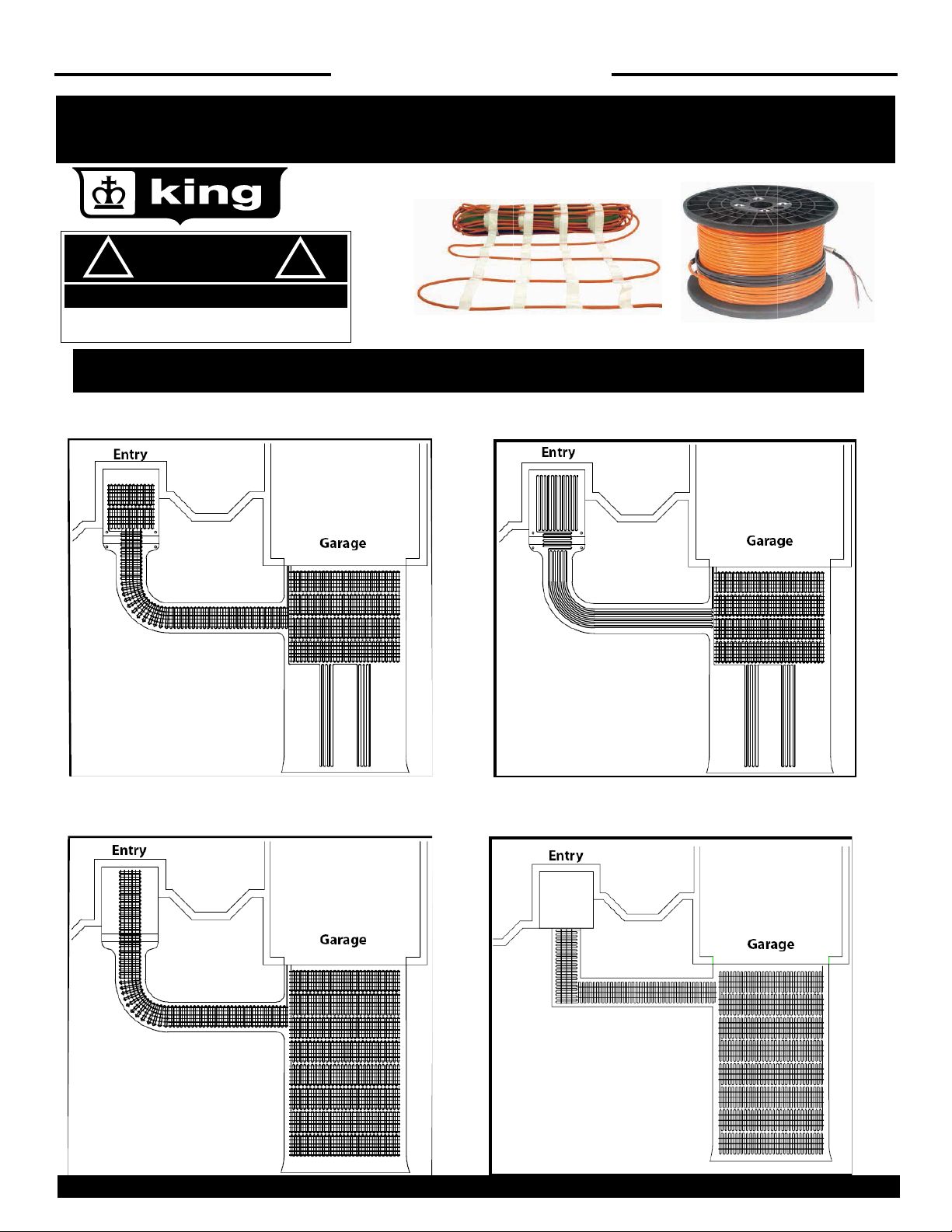
Typical SC/SCM Installation Coverage Configurations
Driveway with full coverage near garage and "tire track" coverage down driveway
SX Mats and Cables can be used in combination to fit a variety of areas
KING ELECTRIC MFG CO · 9131 10TH AVENUE SOUTH · SEATTLE, WA 98108 · PH:206 762 0400 · FAX: 206 763 7738 · www.king-electric.com
3
Page 4
SAVE THESE INSTRUCTIONS
INSTALLATION INSTRUCTIONS
!
ELECTRIC SHOCK OR FIRE HAZARD
READ ALL WIRE SIZING, VOLTAGE REQUIREMENTS AND SAFETY
DATA TO AVOID PROPERTY DAMAGE AND PERSONAL INJURY
DANGER
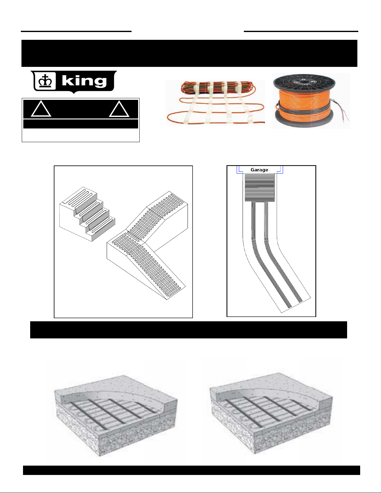
SC Mats and Cables can be used in combination to fit a variety of areas
!
SURFACES THAT CAN BE INSTALLED UNDER
SC embedded in Concrete SC embedded in Asphalt
KING ELECTRIC MFG CO · 9131 10TH AVENUE SOUTH · SEATTLE, WA 98108 · PH:206 762 0400 · FAX: 206 763 7738 · www.king-electric.com
4
Page 5
SAVE THESE INSTRUCTIONS
INSTALLATION INSTRUCTIONS
!
ELECTRIC SHOCK OR FIRE HAZARD
READ ALL WIRE SIZING, VOLTAGE REQUIREMENTS AND SAFETY
DATA TO AVOID PROPERTY DAMAGE AND PERSONAL INJURY
DANGER
!
SURFACES THAT CAN BE INSTALLED UNDER (Continued)
SC under Brick Pavers
SC under Tile
INSTALLATION
Installing the Heating Cable/Mat
Determine general areas where you want to install SC/SCM cable/ mat
Applications include driveways, walkways, patios, permanent ramps, masonry steps and benches, shipping docks, under garage door seals and
more. Anywhere outdoors in residential or commercial locations where snow or icE accumulate may be considered, as long as SC/SCM is
completely embedded in concrete, sand, thick mortar bed, or asphalt.
SC/SCM cable/mat cannot be installed indoors, in industrial locations, or areas with hazardous classifications. It cannot be used for pipe freeze
protection or roof/gutter snowmelt. Do not install the SC/SCM cable/mat on or under non-masonry stairs or decks such as wooden or composite
construction.
If installing SC/SCM under brick pavers we recommend installing cables under entire area. This is because non-heated area will receive melt
water that may re-freeze under the pavers causing the pavers to heave in the non-heated area. (If you have an application you are unsure of,
please consult factory for advice.
KING ELECTRIC MFG CO · 9131 10TH AVENUE SOUTH · SEATTLE, WA 98108 · PH:206 762 0400 · FAX: 206 763 7738 · www.king-electric.com
5
Page 6
SAVE THESE INSTRUCTIONS
INSTALLATION INSTRUCTIONS
!
ELECTRIC SHOCK OR FIRE HAZARD
READ ALL WIRE SIZING, VOLTAGE REQUIREMENTS AND SAFETY
DATA TO AVOID PROPERTY DAMAGE AND PERSONAL INJURY
DANGER
!
INSTALLATION
Make a drawing and measure the area where you want snow melting to occur.
Eliminate those areas where SC/SCM cannot be installed, keeping in mind the following obstructions and allowances.
Cable/Mat cannot be laid within 6” of the edges of slabs. In asphalt, this is increased to 12” from the edge where no curb is provided.
Avoid crossing expansion joints in a slab, unless proper technique and protection steps are followed
Avoid placing the heating cable any closer than 2 inches from other items such as underground cable or piping to keep from overheating
them.
Allow at least 2” between adjacent cables, but not more than 4”, between adjacent cables or sections of a mat where the mat mesh is cut
and turned to fill the area.
Cable/Mat must be laid in such a way that the surface will not have other obstructions placed on top, capturing heat or allowing potential
damage from mounting brackets, bolts, or similar (pedestals, support columns, walls, or light posts).
Precautions:
The heating cable and factory splices of FC/FCM cable/mat must be completely embedded in the concrete, sand, or asphalt. Never try to use
up excess heating cable in surrounding soil, walls, or other unprotected applications.
Never overlap the heating cable on itself or place heating cable closer than 2” from other heating cable.
Only the power lead may exit this area. It will be pulled through conduit to protect it up to a junction box
NEVER pull any of the heating cable or factory splices into any conduit.
WARNING
!
THE HEATING CABLE CANNOT BE CUT TO LENGTH. Order the correct size cable or mat to fit the area. Modifying the heating cable is not
allowed and may lead to overheating, damage, and fire hazard.
Determine junction box (s) location:
It is important to locate the junction box(s) as close as possible to where the SC/SCM cable/mat power leads will terminate, while making sure the
cable (s) and/or mat (s) you select fill the area correctly.
It is best to locate junction boxes on a wall indoors and within the distance of the power leads on the cable/mat. SC/SCM cable/mat comes
standard with 20’ long power leads.
If a junction box must be located outdoors, it is recommended to be installed above grade and to be properly listed for rain tight use outdoors. If
it must be installed at or below grade, use properly listed watertight items and follow box manufacturer guidelines for protection and connection
KING ELECTRIC MFG CO · 9131 10TH AVENUE SOUTH · SEATTLE, WA 98108 · PH:206 762 0400 · FAX: 206 763 7738 · www.king-electric.com
6
Page 7

SAVE THESE INSTRUCTIONS
INSTALLATION INSTRUCTIONS
!
ELECTRIC SHOCK OR FIRE HAZARD
READ ALL WIRE SIZING, VOLTAGE REQUIREMENTS AND SAFETY
DATA TO AVOID PROPERTY DAMAGE AND PERSONAL INJURY
DANGER
!
INSTALLATION
Select the Cable (s) or Mat (s) you need
WATTAGE
Decide what heat output is required. Your design must consider weather conditions and how critical it is to clear the heated area.
50 watts per square foot: sufficient to clear most moderate and heavy snowfall rates.
35 watts per square foot: sufficient to clear most light to moderate snowfall rates.
SIZE
Select a cable or mat to fit the heated area measured in on Page 6. Cable/Mat are manufactured in a variety of sizes. If the exact size of cable or
mat is not available, select the next smaller cable size.
AMPS and VOLTS
Pay careful attention to the amps to make sure your controls, circuit breaker panel, and all wiring will have the proper capacity. Design circuit
protection and wiring to handle 125 percent of heating cable load:
20 amp circuit for load up to 16 amps
30 amp circuit for load up to 24 amps
40 amp circuit for load up to 32 amps
50 amp circuit for load up to 40 amps
70 amp cricuit for load up to 50 amps
Consult with your electrician to make sure the mats/cables, control, and design you have selected will work properly
The SC/SCM cable/mat and its control must be placed on a dedicated power supply from the circuit breaker panel.
The SC/SCM cable/mat is resistance heating system and should be considered as a continuous load for branch circuit sizing purposes.
The circuit breaker must open all ungrounded conductors at the same time. A GFCI type (typically Class B, 30 mA trip) is required to directly
protect the SC/SCM cable and mat.
Circuit breaker size and circuit wiring should be designed to 125 percent of heating mat load:
20 amp circuit for load up to 16 amps
30 amp circuit for load up to 24 amps
40 amp circuit for load up to 32 amps
50 amp circuit for load up to 40 amps
70 amp circuit for load up to 50 amps
Follow NEC, CEC, and local code guidelines for branch circuit wiring, conduit, and junction box installations. Outdoor and underground junc-
tion boxes and conduit must meet rain tight or watertight requirements as required.
KING ELECTRIC MFG CO · 9131 10TH AVENUE SOUTH · SEATTLE, WA 98108 · PH:206 762 0400 · FAX: 206 763 7738 · www.king-electric.com
7
Page 8

SAVE THESE INSTRUCTIONS
INSTALLATION INSTRUCTIONS
!
ELECTRIC SHOCK OR FIRE HAZARD
READ ALL WIRE SIZING, VOLTAGE REQUIREMENTS AND SAFETY
DATA TO AVOID PROPERTY DAMAGE AND PERSONAL INJURY
DANGER
!
INSTALLATION
Verify everything before the installation
Remove the SC/SCM cable/mat, control, and sensor from their packages. Inspect them for any visible damage and verify everything is the correct size and type according to your plan. Do not attempt to install a damaged product.
Record the cable/mat information on the Cable/Mat Testing Log on page 19 . Give this information to the homeowner to keep in a safe place.
The cable/mat model number, serial number, voltage, and resistance range are shown on a nameplate label attached to the power leads.
Do not remove this nameplate label. The electrical inspector will need to see this.
Important
Before installing the FC/FCM cable/mat, make sure to fully check out the products, and carefully plan your site. The following steps may not
necessarily occur in the order shown, depending on contractor and electrician scheduling and variations in site preparation requirements. A
good discussion with all parties involved will help eliminate costly errors and damages.
Measure the resistance
Use a digital multi-meter to measure the resistance between the conductors of the mat power leads. Record these resistances on the
Cable/Mat Testing Log under section “Test Record # 1 Prior to Installation”. The resistance between the white and black lead wires
should be within the resistance range on the nameplate label. If it is a little low, it may be due to low air temperatures or meter calibration.
Consult the factory if you are in doubt.
The resistance between the white and black leads and ground lead should be “open”, usually indicated by an “OL” or whatever your meter
shows when the test leads and ground lead should be “open”, usually indicated by a reading. Record this information and contact the factory before installing. This could indicate damage, test lead problems, or a number of other issues. Try “pinning” the test leads to the cable/
mat lead wires against a hard non-metal surface if your readings fluctuate.
Your electrician should perform an insulation resistance test on the mat. A mega ohm meter adjusted to a minimum 1000 VDC should give a
measured value at least 20 mega ohm (MΩ).
WARNING
!
IMPORTANT! Use King’s Cable Alarm Monitor during installation.
It is recommended to use the King’s Cable Alarm Monitor (Model # FCS11) during installation. When con-
nected, the device will constantly monitor the heating wire during the entire installation process. If the
wire is cut or damaged during installation, this device sounds an alarm. The FCS11 will prevent burying a
damaged wire below hardened concrete.
Mega Ohm meters apply high voltage and could shock or cause serious injury if improperly used.
Follow mega ohm meter instructions for safe and proper use.
KING ELECTRIC MFG CO · 9131 10TH AVENUE SOUTH · SEATTLE, WA 98108 · PH:206 762 0400 · FAX: 206 763 7738 · www.king-electric.com
8
Page 9

SAVE THESE INSTRUCTIONS
INSTALLATION INSTRUCTIONS
Electrical Installation
Install junction boxes in the location (s) planned during the design process (Refer to page 6 under “Determine Junction Box(s) Location”).
Install conduit and branch circuit wiring from the circuit breaker panel to the control location, and from the control to the junction boxes.
Follow local code for wire size, conduit requirements, and proper installation procedure.
Install conduit from the junction box to the edge of the slab to be heated. Extend this conduit into the slab edge about 2”-6” and attach a
bushing to the end to prevent damaging the cable/mat power leads.
Plan carefully if you are installing edge pavers, edge drainage systems, landscaping, or other items that affect where the conduit comes in.
If a slab sensor is to be embedded in the heating area, install conduit from the control location to the desired slab location. Follow the sensor
instructions for proper placement and connections.
Install the circuit breaker size and type as determined earlier. DO NOT connect the branch wiring to the breaker yet.
Label the circuit breaker in the panel which feeds this Snow Melt system with “Snow Melt” or similar.
Sensor Installation
Installing a Feeder Cable
A feeder cable for a sensor may be needed. A 50’ (15m) cable is supplied with each sensor. Approx. 1.5’ (0.5m) of this cable should be coiled
inside the bottom of the sensor tube. The remaining cable may be lengthened. The feeder cable must be four wire cable.
Installing a Sensor and a Conduit
The sensor and the conduit may be installed in connection with the actual construction work and connected at a later date. The following applies
for all types of installations:
Ensure that the conduit is sealed when the concrete is poured.
The conduit must be positioned so that it is flush with the surrounding terrain. The sensor must be placed so that the upper brass sur-
face is horizontal.
The base below the tube must be hard, e.g. a concrete tile, in order to ensure that the sensor is not pushed into the ground if for exam-
ple a vehicle runs over it. The tube is designed to be mounted on a plate using the two screw holes inside the conduit.
A metal/plastic pipe, through which the sensor cable may be passed, should be run as far as the sensor conduit.
Coil approx. 1.5’ (0.5m) of the sensor cable inside the conduit.
Place the sensor inside the tube until it is horizontally flush with the edge of the conduit and resting on the internal collar inside the con-
duit. The sensor may be extracted at a later date using the two holes found around the edge of the sensor conduit. The grooves on the
outside of the sensor should correspond with the holes in the conduit.
KING ELECTRIC MFG CO · 9131 10TH AVENUE SOUTH · SEATTLE, WA 98108 · PH:206 762 0400 · FAX: 206 763 7738 · www.king-electric.com
9
Page 10

SAVE THESE INSTRUCTIONS
INSTALLATION INSTRUCTIONS
WARNING Installation in Asphalt, the temperature must not exceed 176°F (80°C) around the sensor/tube. A wooden block or similar place hold-
!
er may be used in the area where the tub/sensor can be placed subsequently. The installation pipe used for the sensor cable should, in that
case, be a metal tube that can withstand high temperatures.
Placement of Ground Sensors
Correct placement of the sensor(s) is important for the system to work as intended. Some basic guidelines follow:
The number of ground sensors:
The more sensors added to the system the better the performance.
The basic principle is to place one sensor where the snow/ice will appear first (for fast detection) and one sensor where the snow/ice will
disappear last (for complete melting). Just place the sensors as far apart as possible.
With only one sensor you will have to decide what is most important:
a) Fast detection and activation of the system or
b) Securing a complete melting of all snow/ice. A one sensor ground system will be slower in terms of detection and activation than a
two senso4r ground system, where one sensor measures the ground temperature and the other sensor measures the moisture.
Use two or more to cover problem spots where snow usually is not detected or where snow is not completely when the system shuts down.
Placement of Individual Ground Sensors
The sensor must be placed within the heated area and at least 3.3’ (1m) from the edge of the area.
The sensor must be placed in between the heating cables—a minimum distance of 0.4” (1 cm) should be maintained between the sensor
tube and the heating cable.
There must be a minimum distance of
3.3’ (1 m) between the two sensors. (As
shown in diagram below)
KING ELECTRIC MFG CO · 9131 10TH AVENUE SOUTH · SEATTLE, WA 98108 · PH:206 762 0400 · FAX: 206 763 7738 · www.king-electric.com
10
Page 11

SAVE THESE INSTRUCTIONS
INSTALLATION INSTRUCTIONS
Prepare the base material
Prepare the site that you want to heat with the SC/SCM cable/mat. This includes making sure all utilities and obstructions are accounted for.
Lay a smooth, well-compacted gravel base. Ensure proper slope and drainage to avoid water buildup in any heated or surrounding areas. This
is especially important for brick paver applications, as melted water may re-freeze and heave surrounding sand and paver areas. Follow local
building code and construction guidelines for grade thickness and type.
Make sure you account for the total grade and slab thickness as required for pedestrian and vehicular traffic use. If the cable/mat is to be
placed on an existing pavement, make sure it is inspected for any sharp objects, loose sections, or other potentially damaging issues that could
cause problems later. It is very important for the cable to be completely embedded.
Prepare to install
Determine a time to install the cable/mat when equipment, heavey tools, and site traffic will be minimal to keep from possibly damaging the
product. Be prepared to apply the surfacing courses over the cable/mat the same day so it will be protected from damage.
If installing cable/mat in the upper layer of a two-stage concrete slab or the upper layer of an
asphalt application, the cable or mat should be completely ready for the stage. There is limited
time between stages, as the slab should not be allowed to fully cure or the asphalt to
completely cool. Therefore, if using SC/SMC cable, you may want to lay it out and tie it to
rewire that can be quickly lifted into place after the first is laid. This might also be preferable for
a mat installation, although if mats are precut and shaped to the area, they generally can be
rolled into place fairly quickly. If a slab sensor is installed in the second layer, plan ahead so
this does not cause the first layer to cure or cool too much.
Inspect the area and remove any sharp objects. Install in temperatures at least 40 degrees F
(4.5 degrees C)
Begin by test-fitting the cable or mat in the area to be heated
For mat, unroll it completely. Turn and flip it by cutting the tape where needed. Make sure it fits the area properly. For cable, make sure it fits
the area with no excess cable.
Important Cable CANNOT be cut shorter to fit. Do not overlap or cross over heating cable on itself. Do not space heating cable closer than 2”.
Cable/mat cannot be laid closer than 6 inches from the edges of slabs. In asphalt, no closer than 12” from the edge where no curb.
Avoid crossing expansion joints in a slab, unless proper technique and protection steps are followed
Avoid placing the heating cable any closer than 2” from other items such as underground cable or piping to keep from overheating
them.
Allow at least 2”, but not more than 4”, between adjacent mats or sections of a mat where the mat tape is cut and turned to fill the
area.
Do not repeatedly bend the heating cable, and never bend factory splices.
Place the power leads of the cable/mat next to the conduit entry. The electrician will pull this through the conduit later. Make sure it is
positioned so that the no part of the splice connection or the heating cable will be pulled into the conduit.
WARNING
!
The heating cable and factory splices of the SC/SCM cable/mat must be completely embedded in the concrete, sand, or asphalt. Never try to use up excess cable in surrounding soil, walls, or other unprotected applications.
11
Page 12

SAVE THESE INSTRUCTIONS
INSTALLATION — CONCRETE
Installation for Concrete Application:
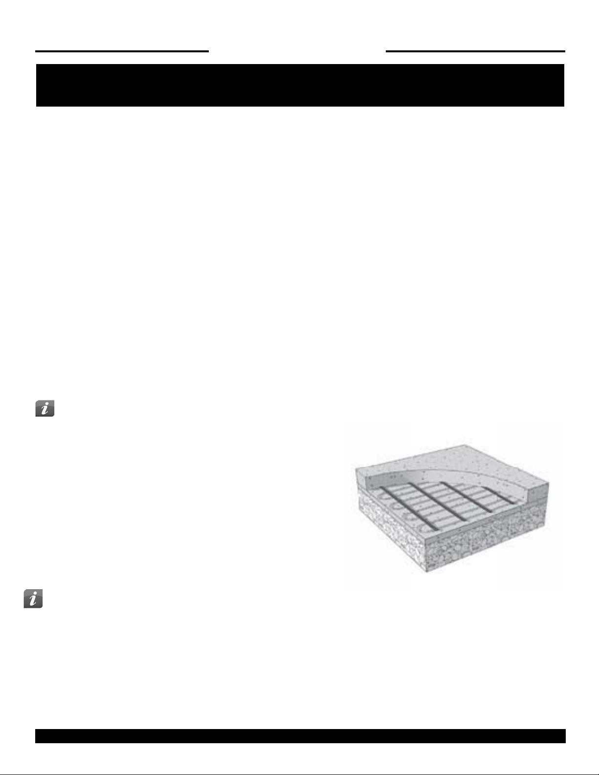
Step 1: Attach reinforcement, such as wire mesh or rebar, over the base at about 2” to 3”
below the level of the intended top surface. You must use “chairs” or other appropriate objects
to raise the wire mesh to the correct level. The SC/SCM cable/mat will be attached to this reinforcement later. It is very important for the cable to be completely embedded in concrete.
Protect or remove sharp protrusions by bending them over, capping, or cutting. Sharp edges
may damage the heating cable.
Step 2A: (For SC cable Installation) Begin securing the heating cable at the desired spacing to
the reinforcement mesh or rebar using plastic cable ties. These cable ties should be applied
roughly every 12” and also at the ends of each run. Turn the cable ends downward so they will
not poke up through the surface layers. Do not use metal ties as they may damage the cable.
Step 2B: (For SCM Mat Installation) Begin laying out and securing the mat about every 12” to the reinforcement mesh or rebar using plastic cable ties around the heating cable. Turn the cable tie ends downward so they will not poke up through the surface layers. Do not use metal ties as
they may damage the cable.
If installing on top of existing slab, secure the mat by nailing through the tape every 2 ft. or so. NEVER strike the heating cable with a hammer.
IMPORTANT Expansion Joints: SC heating cable must never be run through an expansion joint. Doing so may cause damage to the cable
with slab movement. It is recommended to lay the mat so these joints are avoided.
However, if it is necessary, a portion of the heating cable may be dropped into the grade below the expansion joint as shown below. ( Fill around
the cable with at least 1” thick sand. The loop of the heating cable should be long enough to allow flexing, and must not be embedded into the
concrete (the sand will protect this) since this would not allow the cable to flex with slab movement.
KING ELECTRIC MFG CO · 9131 10TH AVENUE SOUTH · SEATTLE, WA 98108 · PH:206 762 0400 · FAX: 206 763 7738 · www.king-electric.com
12
Page 13
SAVE THESE INSTRUCTIONS
INSTALLATION — CONCRETE
Concrete Application continued
Step 3: Use a digital multi-meter to measure the resistance between the conductors of the cable/mat power leads again. Record these re-
sistances in the SC Cable / SCM Mat Testing Log under the section “Test Record # 2 After Installation”.
Step 4: Feed the power leads through the conduit into the junction box, leaving at least 6 inches of free lead length. Securing the heating cable
and splice so that they will not be pulled into conduit.
Insert a generous amount of electrical conduit sealant into the conduit end around the power leads to prevent water entry.
Step 5: If a slab sensor is being installed, place the sensor socket according to the instructions. Secure and seal it to the conduit installed earlier. It should be located halfway between heating cables and in an area recommended by the sensor manufacturer. Make sure the top of the
sensor will be flush with the surface of the finish layer. Make sure it is protected with a cap or seal.
Step 6: Take a photo of the cable/mat installation. This can be very helpful later for utility work, changes to the site, etc to avoid possible
damage. Keep the photos with this installation manual.
Step 7: Before beginning work, inspect the cable/mat for damage and secure any cable/mat that may have come loose.
To avoid burying any possible damage that may have occurred since the mat was laid, the following tests should be performed:
Use a digital multi-meter to measure the resistance between the conductors of the cable/mat power leads again. If possible, your electrician
should perform an insulation resistance test on the cable/mat. A mega ohm meter adjusted to a minimum 1000 VDC should give a measured
value at least 20 mega ohm (MΩ).
Important
Be prepared to install a marker plate or other identification indicating the presence
of SC/SCM in the slab. This helps alert and avoid possible damage from future onsite. Install a marker plate where clearly visible in each snow-melted area. A marker plate is placed flush in the wet concrete surface or soft asphalt surface. Other
types of surfaces should be made to allow the marker plate to be installed flush
with the surface. Do not damage the heating cable.
Step 8: Pour concrete over the base and SC/SCM cable/mat so that no less than 11/2” and no more than 3” covers the top of the heating cables. The slab should be
a minimum of 4” thick total. Driveways normally require thicker. Follow building
code requirements for required thickness.
Important
Do not use sharp tools which could damage the SC/SCM. Blunted shovels should allow you to work the concrete carefully into all areas.
Make sure the heating cable is fully embedded, as well as 2 to 6 inches of the conduits enclosing the power lead and slab sensor wiring (if
used). Allow the concrete to fully cure as required by the concrete supplier. Do not energize the SC/SCM cable/mat except to briefly test it, as
this would improperly accelerate the curing and potentially cause concrete damage.
Step 9: Use a digital multi-meter to measure the resistance between the conductors of the cable/mat power leads again. Record these resistance in SC Cable / SCM Mat Testing Log under the section “Test Record # 3 After Covering is Applied”.
DO NOT energize the SC/SCM system until the asphalt is fully cooled and cured per the manufacturer.
KING ELECTRIC MFG CO · 9131 10TH AVENUE SOUTH · SEATTLE, WA 98108 · PH:206 762 0400 · FAX: 206 763 7738 · www.king-electric.com
13
Page 14

SAVE THESE INSTRUCTIONS
INSTALLATION — CONCRETE
Stairs (Concrete Only) Application: If you are installing TC Cable onto stairs, secure a single run of cable to the side of a riser. Lay 4
or runs of cable on the tread area as needed and continue up each stair following these guidelines:
Lay cable no greater than 3” from the front edge of the finished stair. Not doing so, cable will not melt snow properly.
Lay cable no less than 6” from the side edges of the finished stair.
Account for future hand railings that could be mounted onto staircase, especially in the middle of a long staircase if required. Use a marker
on drawings on the next page to indicate where railing my be installed safely later.
Avoid pinching or sharply bending the cable. At the corner of the stair, keep a minimum 1” radius bend, but secure it flat enough that the
surface concrete or pavers will not pinch the cable.
Do not install the cable on or under non-masonry stairs such as wooden or composite construction.
SCM Mat on Stairs
SC Cable on Stairs
Turn Techniques for SCM mats
If you need to cut and turn the mat, or fill odd areas, you may use scissors to carefully cut the tape holding the heating cables. Heating cables
should be secured at about 3” apart, and no less than 2” apart.
Important—Be careful not to kink or sharply bend the heating cable. A minimum bend radius of 1” should be maintained.
KING ELECTRIC MFG CO · 9131 10TH AVENUE SOUTH · SEATTLE, WA 98108 · PH:206 762 0400 · FAX: 206 763 7738 · www.king-electric.com
Curved
14
Page 15

SAVE THESE INSTRUCTIONS
INSTALLATION — PAVER / STONE
Stone or Paver Application
Step 1: Follow guidelines recommended by the paver manufacturer. If a coarse of sand is to be
applied over the gravel base, the cable/mat must first be secured in place and then covered with
a minimum 1-1/2 inch layer of to completely embed the mat.
Step 2A: (For SC Cable Installations) Secure plastic mounting cable ties to gravel base, driving
long nails or similar through the head of the cable tie. These cable ties should be applied at the
end of each run and at every 3—4 feet. Do not use metallic cable ties as they may damage the
cable. Lay out the cable and secure with the cable ties.
Step 2B: (For SCM Mat Installations) Begin laying out the mat and secure it onto the base with
landscape fabric stakes or similar over the mat tape every 2 feet or so. Make sure it is laid flat. Do
not use metallic stakes or staples directly over the heating cable. Be careful not to damage the heating cable.
Step 3: Use a digital multi-meter to measure the resistance between the conductors of the cable/mat power leads again. Record these resistances in SC Cable / SCM Mat Testing Log under the section “Test Record # 2 After Installation”.
Step 4: Feed the power leads through the conduit into the junction box, leaving at least 6 inches of free lead length. Secure the heating cable
and splice so that they will not be pulled into the conduit. Insert a generous amount of electrical conduit sealant into the conduit end around the
power leads to prevent water entry.
Step 5: If a slab sensor is being installed, place the sensor socket according to the instructions. Secure and seal it to the conduit installed earlier. It should be located halfway between heating cables and in an area that is recommended by the sensor manufacturer. Make sure the top of
the sensor will be flush with the surface of the finish layer. Make sure it is protected with a cap or seal.
Step 6: Take a photo of the cable/mat installation. This can be very helpful later for utility work, changes to the site, eSC. to avoid possible
damage. Keep the photos with this installation manual.
Step 7: Before beginning work, inspect the cable/mat for damage and secure any cable/mat that may have come loose.
To avoid burying any damage that occurred since the mat was laid, the following tests should be preformed:
WARNING
!
should give a measured value at least 20 megohm (MΩ).
Important
Be prepared to install a marker plate indicating the presence of SC/SCM in the slab.
This helps alert and avoid possible damage in the future. Install where clearly visible in each snow-melted area. A marker plate is placed flush with the pavers.
Use a digital multi-meter to measure the resistance between the conductors of the cable/mat power leads. If possible, your
electrician should perform an insulation resistance test on the cable/mat. A megohm meter adjusted to a minimum 1000 VDC
Step 8: Manually spread sand over the top of the cables and base so that no less
than 1-1/2 inches covers the top of the heating cables. Be careful not to use sharp
tools. Compact the sand as recommended by the paver supplier, being careful not
to uncover any of the SC/SCM cable/ mat and not to damage the conduits coming
into the slab area. Use hand compactingtools around the conduit area. Add more
sand if necessary to maintain minimum 1-1/2 inches over all of the cables and
conduit.
Place the pavers over the top and finish as required.
15
Page 16

SAVE THESE INSTRUCTIONS
INSTALLATION — TILE
Stone or Paver Application continued:
Important Make sure the heating cable is fully embedded as well as 2 to 6 inches of the conduits enclosing the power lead and slab
sensor wiring (if used).
It is highly recommended that pavers be no more that 2-1/2 inches thick.
Step 9: Use a digital multi-meter to measure the resistance between the conductors of the mat/cable power leads again. Record the results in
SC Cable / SCM Mat Testing Log under the section “Test Record # 3 After Covering Is Applied”.
Ceramic or Stone Tile Application
Step 1: SX mats or cables can be installed in the structural slab or in a thick mortar bed above a
structural slab. In either case, the base material should be prepared according to section 7.12.1
Concrete Application.
Step 2A: (For SX Mat Installations) Begin laying out the mat and secure it onto the base with
landscape fabric stakes or similar over the mat tape every 2 feet or so. Make sure it is laid flat.
Do not use metallic stakes or staples directly over the heating cable. Be careful not to damage
the heating cable.
Step 2B: (For SX Cable Installations) Secure plastic mounting cable ties to the gravel base,
driving long nails or similar through the head of the cable tie. These cable ties should be applied
at the end of each run and at every 3 to 4 feet. Do not use metallic cable ties as they may damage the cable.
Lay out the cable and secure with the cable ties.
Step 3: Use a digital multi-meter to measure the resistance between the conductors of the mat/cable power leads again. Record these resistances in SC Cable / SCM Mat Testing Log under the section “Test Record # 2 After Installation”.
Step 4: Feed the power leads through the conduit into the junction box, leaving at least 6 inches of free lead length. Secure the heating cable
and splice so that they will not be pulled into the conduit.
Insert a generous amount of electrical conduit sealant into the conduit end around the power leads to prevent water entry.
Step 5: If a slab sensor is being installed, place the sensor socket according to the instructions. Secure and seal it to the conduit installed
earlier. It should be located halfway between heating cables and in an area that is recommended by the sensor manufacturer. Make sure the
top of the sensor will be flush with the surface of the finish layer. Make sure it is protected with a cap or seal.
Step 6: Take a photo of the mat/cable installation. This can be very helpful later for utility work, changes to the site, etc. to avoid possible
damage. Keep the photos with this installation manual.
Step 7: Before beginning work, inspect the mat/cable for damage and secure any mat/cable that may have come loose.
To avoid burying any possible damage that may have occurred since the mat was laid, the following tests should be performed:
Use a digital multi-meter to measure the resistance between the conductors of the mat/cable power leads again (see
Step 7.7). If possible, your electrician should perform an insulation resistance test on the mat/cable. A megohmeter adjusted to a minimum
1000 VDC should give a measured value at least 20 megohm (MΩ).
Important
Be prepared to install a marker plate or other identification indicating the presence of SX in the slab. This helps alert and avoid possible damage from future on-site. Install a marker plate where clearly visible in each snow-melted area. A marker plate is placed flush in the wet concrete surface or soft asphalt surface. Other types of surfaces should be made to allow the marker plate to be installed flush with the surface.
Do not damage the heating cable.
KING ELECTRIC MFG CO · 9131 10TH AVENUE SOUTH · SEATTLE, WA 98108 · PH:206 762 0400 · FAX: 206 763 7738 · www.king-electric.com
16
Page 17

SAVE THESE INSTRUCTIONS
INSTALLATION — TILE
Ceramic or Stone Tile Application continued:
Step 8: For either application below, exterior-grade materials should be selected and
installed per manufacturer’s recommendations. Only vitreous tile (non-porous) tile should
be used as other tile will absorb moisture which will lead to failure. The maximum thickness above the cable should be no less than 1.5” and no more than 2.5”. A movement
joint should be installed between any heated and non-heated area.
1) Dry-set or Latex-Portland Cement (thin-set) Mortar Application - In this application, the
mat or cable is already installed in the concrete slab. The primary concern is to install a
cement mortar bond coat (thin-set) and tile according to Tile Council of North America
(TCNA) recommendations for exterior applications (F102-07). Mortar
and grout materials should be as specified per American National Standards Institute
(ANSI) for exterior applications.
2) Cement Mortar or Thick-set Application - In this application, the mat or cable is installed above the structural slab in a thick mortar bed and
bond coat according to TCNA F101.07. A 1.25” minimum mortar bed should be placed over the cable or mat according to ANSI A108.1A
guidelines. Above this layer, the mortar bond coat and tile is installed.
Step 9: Use a digital multi-meter to measure the resistance between the conductors of the mat/cable power leads again. Record these resistances in SC Cable / SCM Mat Testing Log under the section “Test Record # 3 After Covering Is Applied ”.
Controls and Sensors Installation
• De-energize all circuits feeding this system before doing any electrical work.
• If a slab sensor is being installed, uncover the cap or seal on the embedded sensor socket. Feed the sensor leads through the conduit up to
the control. Secure the sensor into the socket and finish this installation as required by the sensor manufacturer.
• Make wire connections at junction boxes for the SC Mat/Cable power leads to the power wiring from the control. If the junction box is located outdoors, it is highly recommended to use wet location rated wire nuts or crimps to avoid corrosion.
• Install the control at its location according to the instructions provided with the control. Make wiring connections to the power source and
to the sensor wires and mat/cable lead wires.
Important The ground wire supplied with the mat/cable must be connected to a suitable grounding/earthing terminal.
• After careful inspection of all wiring, connect the power supply wiring to the GFCI type circuit breaker and turn it on.
• Follow instructions for the control to set it up. The sensor should not allow the system to energize the SC until proper conditions exist. The
control may allow you to temporarily test the system for just a few minutes. If you have a clamp-on type electrical test meter, energize the
system briefly and verify it is drawing the proper level of current into the mat/cable as planned.
Important Do not fully energize the SC, except for this brief test, until the concrete is cured or asphalt is cool. This could cause
improper curing of the surface materials.
CAUTION: Do not operate the system with air temperatures above 50℉(10℃) except for this brief test. This will stress the materials and
reduce the life of the heating cable and may cause damage to the materials and heating cables.
KING ELECTRIC MFG CO · 9131 10TH AVENUE SOUTH · SEATTLE, WA 98108 · PH:206 762 0400 · FAX: 206 763 7738 · www.king-electric.com
17
Page 18

SAVE THESE INSTRUCTIONS
FINAL COMMISSIONING
Commissioning
Important
For the extended limited warranty to apply, you must perform these tests, record the results on the SC / SCM Testing Log, and retain
a copy of the record.
Insulation Resistance Test with a megohmeter
This test ensures that the insulating jackets of the cable are not damaged. A low value indicates the cable has been damaged and must be
replaced. A megohmeter adjusted to a minimum 1000 VDC should give a measured value at least 20 megohm (MΩ).
WARNING
!
• Connect the ground wire to the black lead and both power wires to the red lead of the megohmeter.
• Adjust the megohmeter to a minimum 1000 VDC.
• Make sure the megohmeter reads at least 20 megohm (MΩ). If you get a different reading, contact the factory.
Record these readings on the SC / SCM Testing Log under section “Record 4: Final Commissioning”.
Megohmeters apply high voltage and could shock or cause serious injury if improperly used. Follow megohmeter instructions
for safe and proper use.
Insulation Resistance Test with a digital multi-meter
This test ensures that the insulating jackets of the mat are not damaged. A low value indicates the cable has been damaged and must be replaced.
• Connect the ground wire to the black lead and both power wires to the red lead of the multi-meter.
• Make sure the meter reads “Open” or “OL” or whatever your meter shows when the test leads are not touching anything. If you get a different reading, contact the factory.
• Record these readings on the SC / SCM Testing Log under section “Record 4: Final Commissioning”.
Heating Cable Resistance Test
This test measures the resistance of the SC Cable . SCM Mat and is used to determine circuit integrity.
Set your multimeter to the 200 or 2000 ohm range.
Connect the multimeter leads to the black and white cold lead wires.
Compare this resistance reading to the resistance specified in the Product Selection “Table 1 or Table 2”. The value should be within
±10%. If you get a different reading, contact the factory.
Record these readings on the SC / SCM Testing Log under section “Record 4: Final Commissioning”.
KING ELECTRIC MFG CO · 9131 10TH AVENUE SOUTH · SEATTLE, WA 98108 · PH:206 762 0400 · FAX: 206 763 7738 · www.king-electric.com
18
Page 19

SC Cable / SCM Mat Testing Log
Customer: ___________________________________________
Address: _____________________________________________
____________________________________________________
Phone No: ___________________________________________
Project Reference: _____________________________________
Record 1: Prior to Installation
Cable Type: __________________________________________
Cable Length: _________________________________________
Cable Model No:_______________________________________
Insulation Resistance M Ohms: ___________________________
Tested By: ___________________________________________
Witnessed By: ________________________________________
Record 2: After Installation
Contractor: __________________________________________
Address: _____________________________________________
____________________________________________________
Phone No: ___________________________________________
Date: _________________________________________
Date: _________________________________________
Insulation Resistance M Ohms: ___________________________
Tested By: ___________________________________________
Witnessed By: ________________________________________
Record 3: While Pouring Concrete
Insulation Resistance M Ohms: ___________________________
Tested By: ___________________________________________
Witnessed By: ________________________________________
Record 4: Final Commissioning
Panel Number: _________________________________________
Breaker Number: _______________________________________
Volts: ________________________________________________
Ambient Temperature (deg. F): _____________________________
Recorded Amps: _______________________________________
Tested By: ___________________________________________
Date: _________________________________________
Date: _________________________________________
Date: _________________________________________
Date: _________________________________________
Date: ________________________________________
Witnessed By: ________________________________________
KING ELECTRIC MFG CO · 9131 10TH AVENUE SOUTH · SEATTLE, WA 98108 · PH:206 762 0400 · FAX: 206 763 7738 · www.king-electric.com
Date: ________________________________________
19
Page 20

SAVE THESE INSTRUCTIONS
TROUBLESHOOTING
Troubleshooting
If not qualified to perform electrical installations, it is strongly recommended that a qualified, licensed electrician be hired to install the heating
cables and related electrical components. If problems with the system arise, please consult the troubleshooting guide below. Any troubleshooting work should be done with the power removed from the circuit, unless otherwise indicated. Call the factory for further assistance.
Problem Possible Cause Solution
Mat/cable
resistance
measurement
is outside the
range printed
on the
nameplate
label.
Snow/ice is
not melting.
An analog ohmmeter (using a
moving needle) was used to take
If measurement shows an open or
short circuit, the heating cable has
If measurement is just a little low
or high, air temperature has affected the resistance.
The resistance measurement
could be from more than one mat/
The ohmmeter (multimeter) is set
to the wrong scale.
Mat/cable has been damaged.
GFCI has tripped.
Incorrect voltage applied.
Obtain a digital ohmmeter (multi-meter) able to read 0 to 20,000 ohms
(Ω) and re-measure the resistance.
Record resistances between all power lead wires and contact the manufacturer.
Place the mat/cable in a room 65-75 °F and re-measure after an hour.
Disconnect all cables/mats from each other and from controls and remeasure.
If the ohmmeter (multi-meter) has multiple ranges (e.g. 200Ω, 2kΩ,
20kΩ, 200kΩ, 20MΩ) set the range to 200Ω and re-measure.
Measure mat/cable resistances between all power lead wires as shown
in 7.7 of this manual. If there is an open or short-circuit damage, record
Try resetting the GFCI on the circuit breaker ONCE. If it trips again, do
not continue to try resetting it. Check for loose wire connections in the
breaker panel, junction boxes, controls, etc. Measure mat/cable resistances between all power lead wires as shown in 7.7 of this manual.
If there is an open or short-circuit damage, record these resistances and
contact the manufacturer.
Briefly energize the system and use a multi-meter to measure the voltage between power lead wires of the mat/cable. Check voltage ratings
for each control and cable to make sure they match. If possible, use an
“amp clamp” meter to measure the
System
operates
continuously.
KING ELECTRIC MFG CO · 9131 10TH AVENUE SOUTH · SEATTLE, WA 98108 · PH:206 762 0400 · FAX: 206 763 7738 · www.king-electric.com
Mats/cables are connected in series.
Incorrect wiring. Control was
“bypassed”.
Faulty control. Relay is not opening
properly.
current into each mat/cable.
Multiple mats/cables must be connected in “parallel”.
Check wire connections. See wire instructions with control and
in this manual.
Check instructions with the control.
20
 Loading...