

Page 1
electrical mfg company • 9131 10th Ave. S. • Seattle, WA 98108 • PH: 206.762.0400 • FX: 206.763.7738 • www.king-electric.com
SMART
KT/MKT Compact Forced Air Heater
**Save These Instructions**
INSTALLATION, OPERATION, AND MAINTENANCE INFORMATION
It is extremely important you verify the electrical power supply is the same voltage as the heater you are
installing. 240 and 120 Volt heaters are not interchangeable. Powering a 120 Volt unit with 208/240 Volt
supply wires will destroy the heater and voids all warranties.
IMPORTANT INFORMATION
This heater has been designed to give safe and lasting service if installed, operated and maintained properly.This sheet contains important
information that should be read completely by the installer before beginning and used as a guide during the installation. This paper should
become the property of the homeowner and be used as a guide for operating and maintaining the heater.
Be sure to read carefully the instructions for selecting a location for the heater to assure that flooring materials are not damaged or the heater is
located in an area where the heated air will cause discomfort.
The fan in this heater draws air in the outer openings in the grill, forces it over the element and out the center of the grill. The heater may be
equipped with a line voltage thermostat in the electrical circuit serving the heater or an optional model T-1 or T-2 thermostat available from your
KING dealer. If a line thermostat is chosen it should be rated at 15 Amps for 120 Volt heaters and 10 Amps for 240 Volt heaters.
WARNING: RISK OF ELECTRIC SHOCK. CAN CAUSE INJURY OR DEATH. IMPROPER INSTALLATION, OPERATION, OR
MAINTENANCE OF ANY ELECTRICAL HEATER CAN CAUSE FIRE OR ELECTRIC SHOCK HAZARDS. THE ELECTRICAL
POWER TO THE HEATER IS TO BE DISCONNECTED BEFORE THE GRILL IS REMOVED FOR CLEANING.
**DO NOT OPERATE THE HEATER WITH GRILL REMOVED**
SLP
®
LIMIT
PROTECTION
U.S. PATENT #6,748,163 B2
CANADIAN PATENT #2,393,882
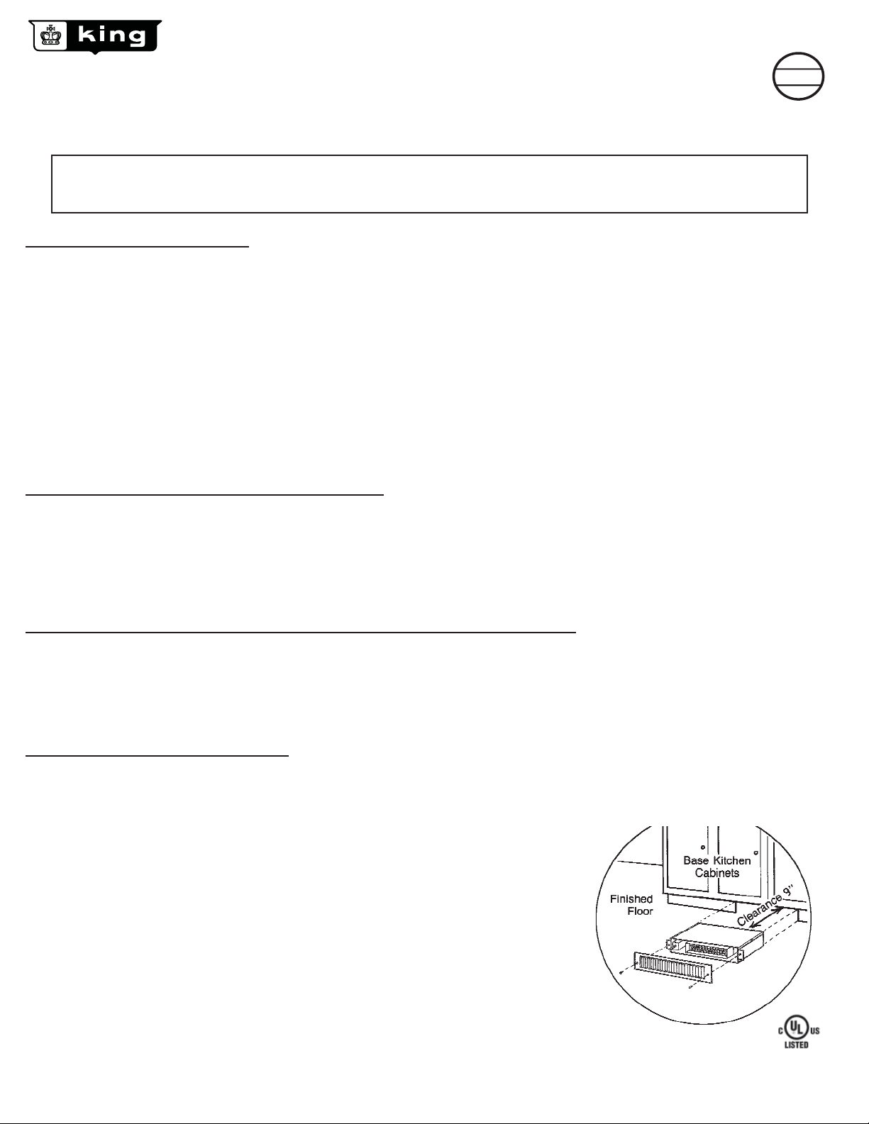
SELECTING A LOCATION FOR THE HEATER
This heater has been designed to allow it to be recessed at floor level in the toe space of cabinets or counters or at the base of walls. When
selecting the location, be sure the materials that will be located in the air heated by this heater (such as floor coverings) will not distort or discolor
at temperatures up to 139°F. DO NOT select a location directly beneath sinks or other work areas where people are likely to stand for extended
periods and will be made uncomfortable by the hot air discharge. DO NOT install less than 6 inches from vertical side walls or open edge of
door. This heater must have an unrestricted airflow. Do not select a location where it is likely to be blocked by furniture, throw rugs, etc. Be sure
the location selected allows sufficient space for the heater as shown by figure 1. Do not locate this heater in an area where combustible vapors,
gases, liquids, or excessive lint, dust or moisture is present.
UNPACKING, INSPECTION AND PREPARATION FOR INSTALLATION
All products are subject to possible damage from mishandling and shipping. A damaged heater can be hazardous. Inspect the heater and
prepare it for installation as follows:
1. Remove the screw in each end of the grill and remove the grill.
2. Remove the two screws on each side of the heater and remove the cover.
3. Inspect the heater for loose, damaged or missing parts.
Report any damage to your dealer and obtain repairs or replacements before installing heater.
INSTALLATION OF THE HEATER
CAUTION: Open the circuit breaker supplying the heater before attempting installation, maintenance, or repairs. Lock or
tag circuit breaker panel door. Failure to do so could result in serious electrical shock, burns, or possible death.
1. Cut a 3-5/8" x 14-1/4" opening at the location selected for the heater.
2. Remove a knockout in the heater wall case and install a cable clamp in the knockout hole.
3. Install a grounded electrical cable from the fuse or circuit breaker box and extend it through
the cable clamp.
NOTE: Be sure the cable is proper size for the electrical load of the heater.
The National Electrical Code requires 14 gauge minimum for these heaters.
4. Attach the groundwire to the ground lug on the wall case and tighten the cable clamp.
5. If the heater is to be equipped with an optional integral thermostat install it at this time.
6. Attach the heater leads (and/or thermostat lead) to the electrical cable with appropriate
fasteners such as wire nuts or solderless connectors.
7. Replace the heater top and slide the heater into its intended location.
8. Fasten the flanges of the heater to the wall surface with screws and reinstall the grill.
9. If the heater is equipped with an optional thermostat, install the thermostat knob and
turn the thermostat knob to its highest setting.
10. Install the fuse or turn the circuit breaker on and check the heater for proper operation.
Figure 1
KT.indd : 4/08
Page 2
MAINTENANCE OF THE HEATER
** BE SURE THE ELECTRICAL POWER TO THE HEATER IS DISCONNECTED BEFORE REMOVING THE GRILL
**DO NOT OPERATE THE HEATER WITH GRILL REMOVED**
The heater should be kept free of lint and dust accumulations. Every six months (or more often if lint accumulations are observed) the grill should
be removed and the heater blown clean with a vacuum cleaner. While the grill is removed it may be cleaned with a soft damp cloth. Abrasive or
solvent cleaners will damage the paint. If repair parts are required use only the proper parts purchased from your KING dealer. Substituting parts
may be hazardous and voids all warranties.
FINAL CHECKLIST
1. Read and follow the installation, operation and maintenance sheet.
2. Be sure to comply with applicable building and electrical codes.
3. Locate the heater where it will not blow heated air on objects that will discolor or
SMART
SLP
LIMIT
PROTECTION
U.S. PATENT #6,748,163 B2
CANADIAN PATENT #2,393,882
distort at 140°/150°F.
4. Attach this heater to a properly fused circuit that is free of all other electrical loads.
5. Be sure the heater is supplied with the correct voltage.
6. Be sure the heater is grounded.
7. Keep all flammable liquids, gases, and pressurized containers away from the heater.
8. Instruct all responsible persons in the proper and safe operation of the heater.
9. Instruct all persons, especially children, of the hazards of tampering with the heater.
10. Keep the air passages through the heater clear of obstructions and lint or dust accumulations.
11. Be sure this sheet becomes the property of all future owners of this heater.
12. Keep the heater in good repair.
This heater includes a manual reset thermal
protector with a self-hold feature. If the heater
®
shuts off with the on position and the room
temperature is below the highest thermostat
setting immediately disconnect the power to
the heater at the circuit breaker and inspect for
any objects on or adjacent to the heater that
may cause high temperatures. After inspecting
the heater, keep the power off to the heater for
10 minutes to reset the thermal protector. If
the heater thermal protector shuts the heater
off again, immediately turn the heater off at
the circuit breaker and inspect the heater for
possible fan motor failure or dirt and lint on the
heating element. Repeat starting procedure.
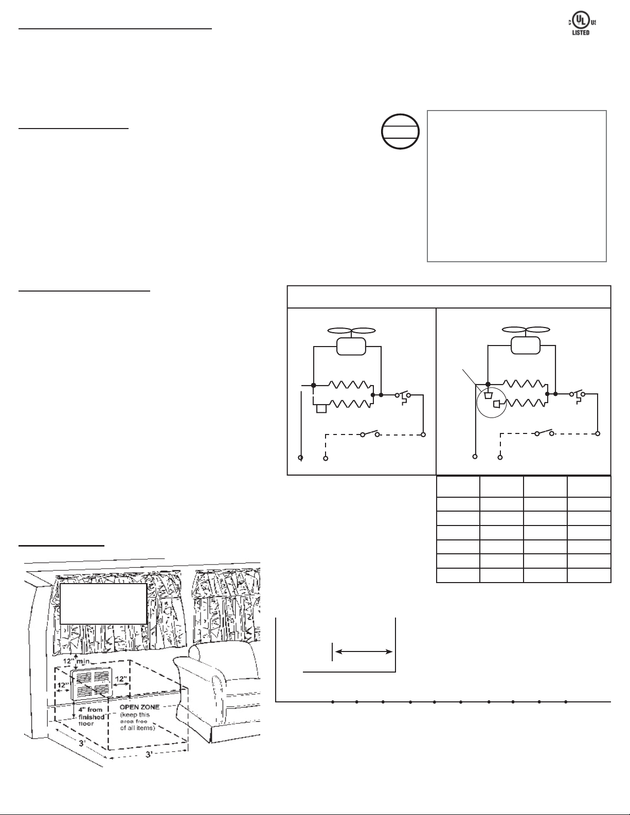
TOE SPACE HEATERS
KT - HEATER WIRING DIAGRAM
CAUTION READ BEFORE INSTALLATION
“CAUTION” - HIGH TEMPERATURES. Linoleum and other
flooring material must be able to sustain temperatures of 139°F
for extended periods of time without discoloring or deterioration.
Many linoleums discolor at low temperatures and from sunlight.
King Electrical Mfg. Company is not responsible for replacement
of discolored flooring material due to hot air from this heater.
Suitable installation and placement selection for this heater is the
responsibility of the end user.
The front cover also has the following markings to caution
owners of high temperatures:
“CAUTION” - SOURCE OF POSSIBLE IGNITION
- HIGH TEMPERATURE KEEP COMBUSTIBLE MATERIALS AWAY FROM
FRONT OF HEATER. DISCONNECT POWER BEFORE SERVICING.
KEEP ANY COMBUSTIBLE MATERIAL AT LEAST 3FEET (.9m) FROM FRONT OF
HEA TER AND A WAY FROM SIDES
CLEARANCES
Two Element - Factory Wiring
FAN
E1
ELEMENT
E2
TAG
L 1
L 2 POWER SUPPLY
THERMOSTAT
(OPTIONAL)
LIMIT
Single Element - Factory Wiring
FAN
Capped
Ends
E1
ELEMENT
E2
L 2
L 1
MODEL VOLTS
KT1210 120 1000 500
KT1212 120 1200 600
KT1215 120 1500 750
KT2410 240 1000 500
KT2412 240 1200 600
KT2415 240 1500 750
THERMOSTAT
(OPTIONAL)
L 2 POWER SUPPLY
2 Element
Wattage
LIMIT
1 Element
Wattage
L 2
FAN-FORCED HEATERS:
Clearances for Safe Operation
cabinet
0"
123°
KT2415 heater
0"
1"
2" 3" 4"
123°
120°
118°
3"
1" 2" 3" 4" 5" 6" 7"
5" 6" 7" 8"
118°
118°
118°
118°
117°
9"
(Average Floor Temperature
116°
± 10% - 70% Ambient)
8" 9"
KT.indd : 4/08
 Loading...