

Page 1
We Manage Heat ®
®
Model LCD®–7A Snow Switch
®
Part Number 21035
Installation Manual
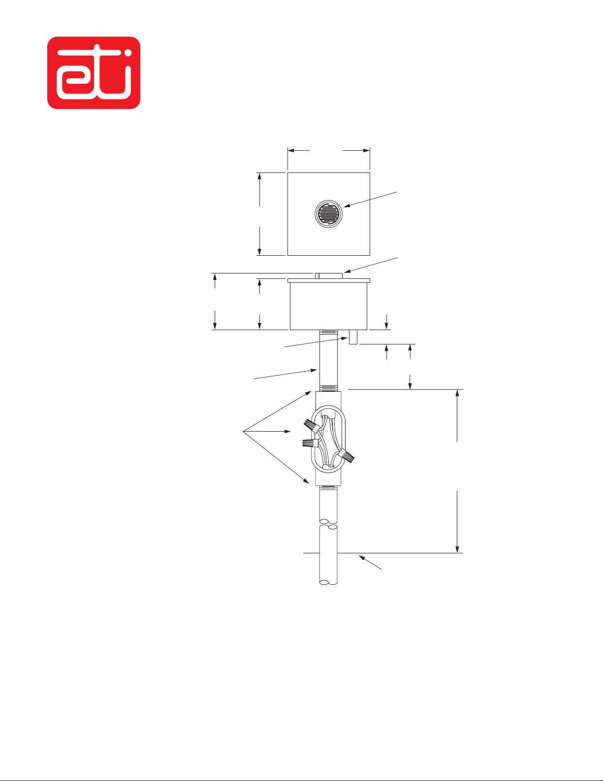
3.86"
(98.1 mm)
Moisture sensing grid.
3.86"
(98.1 mm)
Windshield with
water drain slots.
2.65"
(67.3 mm)
Ambient air temperature sensor.
Cool This Area Per Instructions When Testing
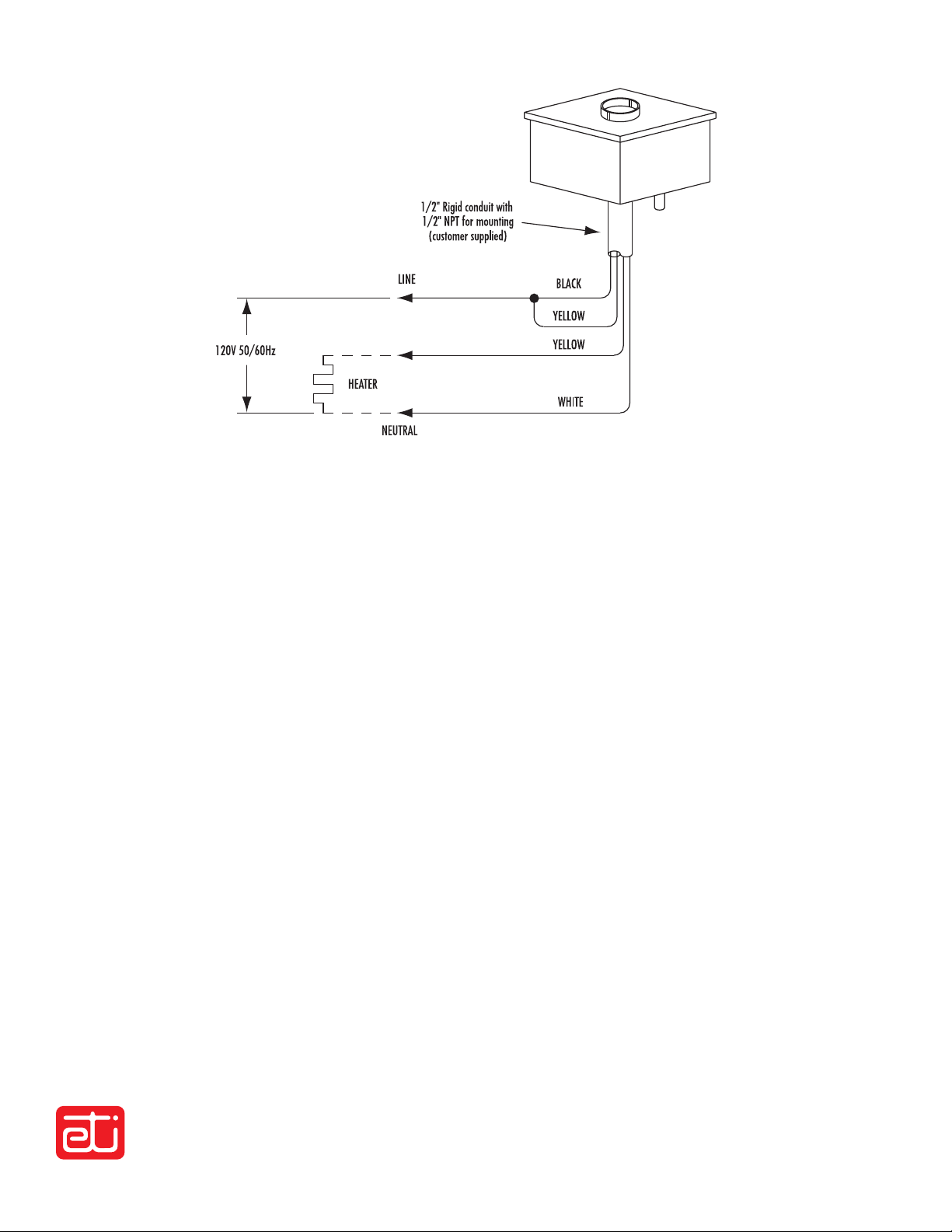
1/2" NPT Galvanized Nipple.
Customer Supplied
Conduit body (or weatherproof box)
and rigid conduit supplied by user.
Make all threaded joints weathertight.
Insulate splices with wire nuts.
2.25"
(57.2 mm)
0.75"
(19.1 mm)
2.00"
(50.8 mm)
Mount rigidly in upright postition
as shown above ground as
necessary to discourage animal
damage and vandalism.
Grade or mounting
support surface.
Installation
Mount sensor securely in upright position in clear (open) area typical of area to be melted, either above roof line or removed from
building as to not be protected from the falling snow.
AVOID overhead trees, shrubs, wires, eaves, etc., and following or blowing debris.
AVOID vehicle and foot traffic. Do not create a safety hazard.
AVOID exposure to artificial heat sources and excessive shock and vibration.
Install per all applicable electrical and building codes and regulations.
Page 2
INSTALL IN ACCORDANCE WITH THE REQUIREMENTS OF ALL APPLICABLE ELECTRICAL AND BUILDING
®
CODES AND REG U LA TIONS. ENSURE THAT ALL CONDUIT/CABLE TERMINATIONS ARE WATERTIGHT.
120 Volt ac, load to 16 amps
®
Post –installation Snow Switch
Most problems result from installation er rors. Before testing,
verify that unit is prop er ly in stalled.
1. Connect power to snow melting sys tem. Wait fi f teen seconds,
system should not ac tu ate.
2. Using ice water or other cooling agent and cool ambient air
tem per a ture sen sor below 38°F(3.3ºC), sys tem should not
ac tu ate. Apply moisture to mois ture sensing grid, system
should actuate in less than 15 sec onds.
3. Dry moisture sensing grid. Disconnect power to snow
melting sys tem. Wait one minute, then reconnect
power. If sys tem ac tu ates ensure sensing grid is dry
and am bi ent air tem per a ture is above 38°F(3.3°C), then
repeat this step.
test
Operating temperature
Range (Min/Max) –40/140°F (-40/60°C)
Setting 38°F (3.3°C)
Tolerance (+/–) 1.5°F (-17°C)
Lockout temperature
Setting ––
Tolerance (+/–) ––
Hold-On Timer
Nominal timer 3 Hr.
Tolerance (+/–) 1%
Output Relay
Rated Voltage (volts a-c 50/60 Hz) 120 Volts
Maximum Load 16 Amps
Supply
Rated Voltage (volts a-c 50/60 Hz) 120 Volts
Tolerance (+/–) 10%
Nominal Power 0.6 Watts
Questions and Comments
For technical help, questions or comments concerning this product or any of Environmental Technology, Inc. products contact Customer
Service between 8:00 a.m. and 5:00 p.m. EST.
Voice: (800)234-4239 in the USA and Canada or (574)233-1202 everywhere
Fax: (888)234-4238 in the USA and Canada or (574)233-2152 everywhere
Email: helpdesk@networketi.com
Web: http://www.networketi.com
DISCLAIMER
Environmental Technology, Inc. makes no representations or warranties, either expressed or implied, with respect to the contents of this publication
or the products that it describes, and specifi cally disclaims any implied warranties of merchantability or fi tness for any particular purpose.
Environmental Technology, Inc. reserves the right to revise this publication and to make changes and improvements to the products described
in this publication without the obligation of Environmental Technology, Inc. to notify any person or organization of such revisions, changes or
improvements.
Environmental Technology, Inc.
1850 N Sheridan Street, South Bend, Indiana 46628
The ETI logo, Snow Switch, LCD and We Manage Heat are reg is tered trademarks of En vi ron men tal Technology, Inc.
© 2008 Environmental Technology, Inc. All rights reserved.
PN21036 rev A 05/08
 Loading...