

Page 1

KX1000
EXTEND
LTE/CELL SIGNAL BOOSTER
User Manual
powered by weBoost
®
Page 2
! !
BEFORE YOU START
Read through this manual before installing
or operating the KING Extend.
If you have any questions,
call KING Customer Service at (952) 345-8147.
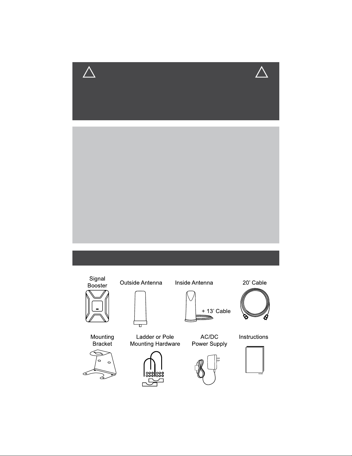
CONTENTS
CONTENTS ................................................................................................. 2
IMPORTANT POINTS ................................................................................. 3
COMPONENT LOCATIONS ....................................................................... 4
OUTSIDE ANTENNA MOUNTING OPTIONS ............................................ 5
INSTALLATION ....................................................................................... 6-7
MEASURING BOOSTER PERFORMANCE ........................................... 8-9
SIGNAL BOOSTER STATUS LIGHT ....................................................... 10
TROUBLESHOOTING .............................................................................. 11
SPECIFICATIONS ............................................................................... 12-13
SAFETY GUIDELINES ............................................................................. 14
WARRANTY .............................................................................................. 15
CONTENTS
Page 2
Page 3
IMPORTANT POINTS
You will need a drill and drill bit, roof-compatible sealant and appropriate
fasteners to install all components and wiring.
The installer is responsible for determining the most appropriate
fasteners to secure the antenna bracket to the roof. Depending on
the roof material, fasteners such as lag screws, well nuts, sheet metal
screws, toggle bolts and T anchors may be used, and should always be
used in combination with a roof-compatible sealant.
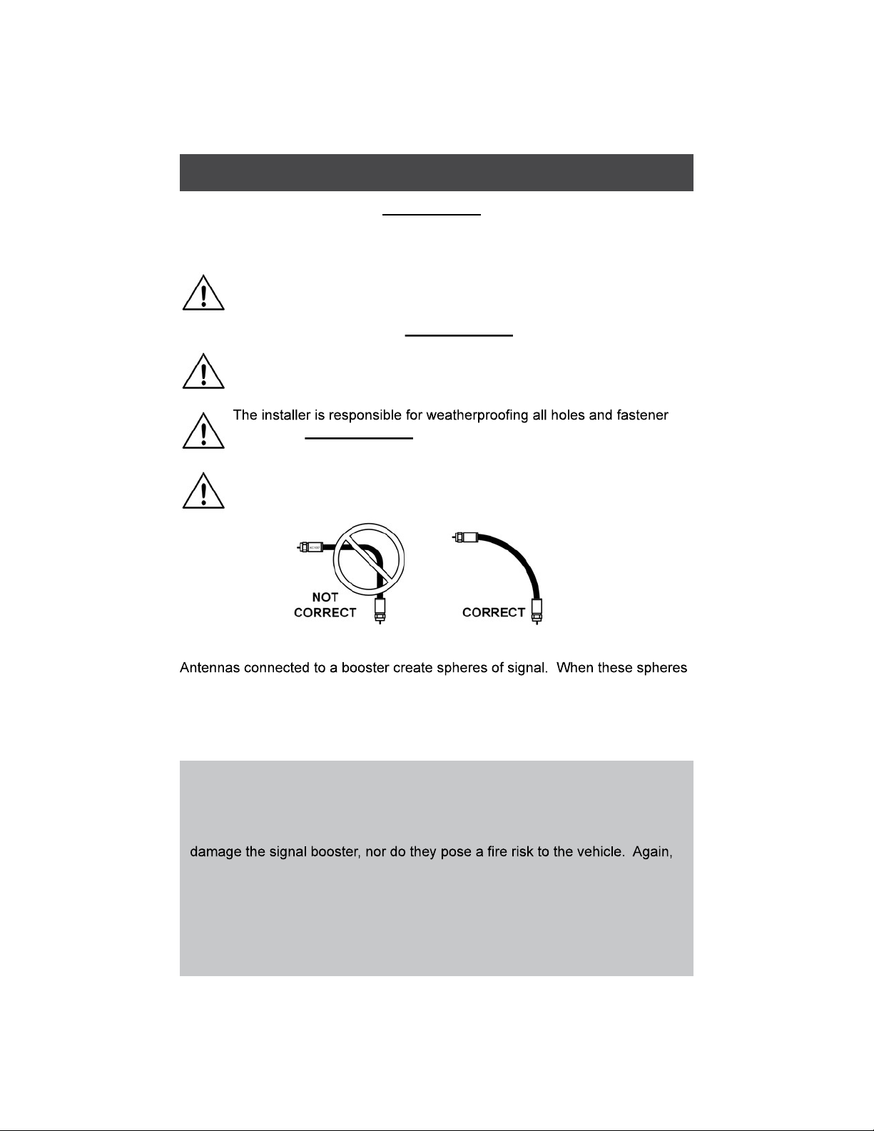
The installer is responsible for properly securing the coax cable to the
roof (for example, cable ties and cable tie mounting pads).
heads with roof-compatible sealant.
Do not put sharp bends in coax cables.
This can reduce signal strength from the antenna.
overlap, a condition called oscillation occurs. Oscillation can be thought of as
noise, which causes the booster to shut down to prevent damage. The best
way to keep these spheres of signal from overlapping is to maximize separation
between the booster and the antenna.
IMPORTANT! The aluminum casing of your signal booster will adjust to the
temperature of its environment, but is designed to protect the signal booster
technology. For example, in the summer, the signal booster case may be
as hot as 150 degrees inside your vehicle. These high temperatures will not
be sure to place your signal booster in a location with adequate ventilation
and away from direct sunlight or moisture.
The signal booster may remain on in vehicles whose 12V DC power sources
do not automatically shut down when the vehicle is turned off. This could
result in discharging the vehicle’s battery in one to two days.
Page 3
Page 4
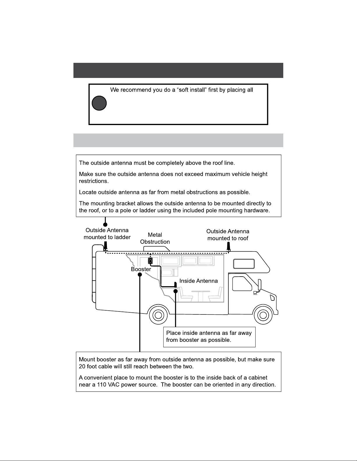
COMPONENT LOCATIONS
components in their chosen locations, completing the setup
instructions, and verifying the system works as desired.
TIP
(Route the cable through an open door or window for the
soft install.)
NOTE: It is up to the installer to determine the best component locations.
Page 4
Page 5

OUTSIDE ANTENNA MOUNTING OPTIONS
Page 5
Page 6

INSTALLATION
1. Fasten the outside antenna to the mounting bracket with the supplied
screws and washers (see page 5).
2. Connect the separate 20’ cable to the antenna (LARGE CONNECTOR).
will penetrate the roof.
4. Fasten bracket to roof. Make sure fastener holes and fastener heads are
properly sealed.
Page 6
Page 7

5. Route the cable to where it will enter the vehicle.
IMPORTANT! Make sure to avoid any cabling, pipes, etc. that may be
damaged by drilling.
6. Drill an appropriately sized hole and feed the cable into the vehicle.
7. Seal the roof hole so it is completely waterproof (inside and outside).
8. Inside, place booster in desired location or install the booster to wall.
Connect cable to booster.
9. Connect inside antenna cable to booster and place inside antenna in
position.
10. Plug booster into power source.
If using the included booster
mounting bracket, remove
the booster from the bracket.
TIP
Fasten bracket to wall, then
snap booster back into bracket.
Page 7
Page 8

MEASURING BOOSTER PERFORMANCE
Note it here:
iPhone
iPhone
IOS 11 - current
®
®
Dial *3001#12345#* then press Call.
1
2 Release the power button.
3 Hold the Home button until your main screen
appears.
If you want to check 3G/1x but your iPhone is picking up
4G/LTE signal , go to Settings>Cellular>Cellular Data
Options>Enable LTE>Select Off.
signal by once again dialing *3001#12345#* then pressing
left corner of your phone.
Android™
as placing calls in different locations. For changes/updates
on this issue, periodically go to weboost.com/signalstrength.
Network Type and Strength (exact options/wording depends
on phone model).
Page 8
Page 9

All Other Phones and Alternate Methods
• https://www.weboost.com/test-mode-instructions/
All Phones:
• Keep track of the network (3G or 4G) the phone is connected to.
readings from other carriers, you will need phones from each carrier.
by dialing *3001#12345#* and pressing Call. Press the signal strength at
the top left of the screen to toggle between numbers and bars. Press the
Home button to exit Field and Test mode.
Compare Results
Having an accurate measurement of signal strength in decibels (dBm)
is crucial when installing your system. Decibels accurately measure the
signal strength you are receiving.
Did you know a signal increase of just 3dB is 2 times the power of signal
Page 9
Page 10

SIGNAL BOOSTER STATUS LIGHT
SOLID GREEN
This indicates your booster is functioning properly and there are no issues
with installation.
BLINKING RED, THEN SOLID GREEN
This indicates one or more of the booster bands has reduced power due to
a feedback loop condition called oscillation. This is a built-in safety feature
to prevent harmful interference with a nearby cell tower. If you are already
experiencing the desired signal boost, then no further adjustments are
necessary. If you are not experiencing the desired boost in coverage, then
refer to the troubleshooting section on the next page.
SOLID RED
This is due to a feedback loop condition called oscillation. This is a built-in
safety feature that causes a band to shut off to prevent harmful interference
with a nearby cell tower. Refer to the troubleshooting section on the next
page.
LIGHT OFF
If the signal booster light is off, verify your power supply has power.
NOTE: The signal booster can be reset by disconnecting and reconnecting the
power supply.
then reconnecting power to the signal booster.
Page 10
Page 11

TROUBLESHOOTING
FIXING BLINKING OR SOLID RED ISSUES
This section is only applicable if the booster is red or blinking red and you
are not experiencing the desired signal boost.
2. Relocate the inside and outside antenna further away from each other. The
objective is to increase the separation distance between them, so that they
will not create this feedback condition discussed before.
3. Plug power supply back in.
4. Monitor the indicator light on your signal booster. If after a few seconds
3. Increase the separation distance until the condition is corrected and/
or desired coverage area is achieved. NOTE: Horizontal separation of
the two antennas typically requires a shorter separation distance than
perpendicular separation.
call KING Customer Service at (952) 345-8147.
Page 11
Page 12

SPECIFICATIONS
Page 12
Page 13

Each signal booster is individually tested and factory set to ensure FCC
compliance. The signal booster cannot be adjusted without factory
reprogramming or disabling the hardware. The signal booster will amplify, but not
alter incoming and outgoing signals in order to increase coverage of authorized
will reduce gain until a signal is detected. If a detected signal is too high in a
frequency band, or if the signal booster detects an oscillation, the signal booster
will automatically turn the power off on that band. For a detected oscillation
the signal booster will automatically resume normal operation after a minimum
permanently shut off until the signal booster has been manually restarted by
momentarily removing power from the signal booster. Noise power, gain, and
linearity are maintained by the signal booster’s microprocessor.
The manufacturer’s rated output power of this equipment is for single carrier
operation. For situations when multiple carrier signals are present, the rating
would have to be reduced by 3.5 dB, especially where the output signal is
re-radiated and can cause interference to adjacent band users. This power
reduction is to be by means of input power or gain reduction and not by an
attenuator at the output of the device.
This device complies with Part 15 of FCC rules. Operation is subject to two
conditions: (1) This device may not cause harmful interference, and (2) this
device must accept any interference received, including interference that may
weBoost could void the authority to operate this equipment.
Page 13
Page 14

SAFETY GUIDELINES
damage your equipment.
The signal booster unit is designed for use in an indoor, temperature-controlled
environment (less than 150 degrees Fahrenheit). It is not intended for use in attics or
similar locations subject to temperatures in excess of this range.
The desktop antenna must have at least 3 feet of separation distance from all active
separation distance from all active users.
Connecting the signal booster directly to the cell phone with use of an adapter will damage
the cell phone.
from all persons.
meters) above ground.
This is a CONSUMER device.
BEFORE USE, you MUST REGISTER THIS DEVICE with your wireless provider
and have your provider’s consent. Most wireless providers consent to the use
of signal boosters. Some providers may not consent to the use of this device on
their network. If you are unsure, contact your provider.
In Canada, BEFORE USE you must meet all requirements set out in ISED CPC-
You MUST cease operating this device immediately if requested by the FCC (or
ISED in Canada) or licensed service provider.
for calls served by using this device.
FOR MORE INFORMATION ON REGISTERING YOUR SIGNAL BOOSTER WITH YOUR
WIRELESS PROVIDER, PLEASE SEE BELOW:
Sprint: http://www.sprint.com/legal/fcc_boosters.html
T-Mobile/MetroPCS: https://support.t-mobile.com/docs/DOC-9827
Page 14
Page 15

WARRANTY
KING Signal Boosters are warranted for two (2) years against defects in
workmanship and/or materials. Should any trouble develop during the warranty
period, contact KING at (952) 345-8147. You must contact KING before the
warranty period expires. The customer must supply proof of purchase (such
as a dated sales receipt) when requesting warranty service. If the customer
cannot supply proof of purchase, warranty period shall start 30 days after date of
manufacture.
reseller with a dated proof of purchase [NOTE: Needs to be discussed].
Signal Boosters may also be returned directly to the manufacturer at the
consumer’s expense, with a dated proof of purchase and a Returned
This warranty does not apply to any Signal Boosters determined by
mishandling that alters or damages physical or electronic properties.
numbers may be obtained by contacting KING Customer Support at
(952) 345-8147.
In no event shall KING be liable for any indirect, incidental, or consequential
damages from the sale or use of the product. This disclaimer applies both during
and after the term of this warranty.
KING disclaims liability for any implied warranties, including implied warranties
warranty.
rights, which vary from state to state. Some states do not allow the exclusion
or limitation of incidental or consequential damages, so the above limitation or
exclusion may not apply to you. Some states do not allow limitations on how
long an implied warranty lasts, so the above limitation may not apply to you.
personal losses arising from its use, or for any infringements of patents or other
rights of third parties that may result from its use.
Page 15
Page 16

Simply better, by design.
™
For patents go to: weboost.com/us/patents.
© 2019 KING
 Loading...