

Page 1
IMPORTANT INSTRUCTIONS
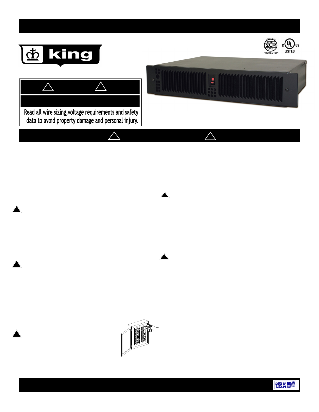
KTW Series Toe Space and Wall Heater
Covers Models: KTW1215/KTW2415
!
DANGER
!
ELECTRIC SHOCK OR FIRE HAZARD
Figure 1
Covers all KTW models
!
WARNING
Read Carefully - These instructions are written in an effort to prevent potential difficulties that might arise during installation. Studying the in-
structions first may save you considerable time and money later. Observing the following procedures will keep installation time to a minimum.
!
IMPORTANT INSTRUCTIONS
When using electrical heating appliances, basic precautions should always be followed to
reduce the risk of fire, electric shock and injury to persons, including the following:
1. Read all instructions before wiring or using this
heater.
2. WARNING: This heater is hot when in use. To avoid burns,
!
do not let bare skin touch hot surfaces. Keep combustible
materials, such as furniture, pillows, bedding, papers,
clothes, boxes, etc., and curtains at least 3 ft. (.9 m) from
the front of the heater and keep them away from the sides
and rear.
3. CAUTION: Extreme caution is necessary when any heater
is used by or near children or invalids and whenever the
!
heater is left operating and unattended.
4. Do not operate any heater after it malfunctions. Disconnect power at service panel and have heater inspected by
qualified electrician for repair before reusing.
5. Do not use outdoors.
6. WARNING: To disconnect heater, turn controls to OFF, and
turn OFF power to heater circuit at main disconnect panel.
7. WARNING: Do not insert or allow foreign objects to
enter any ventilation or exhaust
opening as this may cause an electric
!
shock, fire, or damage to the heater.
8. To prevent any chance of fire, do not
block air intakes or exhaust in any man-
Figure 2
!
!
ner.
9. A heater has hot and arching or sparking parts inside. Do
not use it in areas where gasoline, paint, or flammable
vapors or liquids are used or stored.
10. WARNING: Use this heater only as described in this manual. Any other use is not recommended by the manufacturer and may cause fire, electric shock, explosion or injury
to people and or property.
11. Heater is not intended for use in bathrooms, laundry areas or similar indoor locations. Never locate heater where
it may fall into a bathtub or other water container.
12. This heater includes a over-temperature safety device
that stops the heater from operating. Immediately turn
heater off and inspect for any objects on or adjacent to
the heater that may have blocked the airflow or otherwise caused the high temperatures to have occurred temperatures.
SAVE THESE INSTRUCTIONS
King Electrical Mfg. Co. 9131 10th Ave So. Seattle, WA 98108 206-762-0400 www.king-electric.com
1
Page 2

KTW INSTALLATION INSTRUCTIONS
CAUTION!
Turn OFF all electrical power
to install heater
Figure 2
!
DANGER
!
ELECTRIC SHOCK OR FIRE HAZARD
Selecting A Location For Your Heater: KT
This heater has been designed to allow it to be recessed at floor
level in the toe space of cabinets or under counters or at the base
of walls. When selecting the location, be sure the materials that
will be located in the air heated by this heater (such as floor coverings) will not distort or discolor at temperatures above 140°F
(60ºC). DO NOT select a location directly beneath sinks or other
work areas where people are likely to stand for extended periods of
time. DO NOT install less than 6” (15cm) from vertical side walls or
open edge of door. This heater must have an unrestricted airflow.
DO NOT select a location where it is likely to be blocked by furniture, throw rugs, etc. Be sure the location selected allows sufficient
space for the heater as shown by Table 1. DO NOT locate this heater in an area where combustible vapors, gases liquids, or excessive
lint, dust or moisture is present.
Minimum Horizontal Clearances
When placed in toe space
of a cabinet only. Horizontal
Front Top
36 in 0 in 0 in 0 in
91 cm 0 cm 0 cm 0 cm
TABLE 1
Bottom
Sides
Depth of
Space
KT Heater
Figure 3
Specific to KT Series:
The KT heater is intended for a toe space installation only. Other
grilles are available for a flush surface mount installation that will
trim out the wall can. The heater is designed to be installed in the
toe-space of a cabinet with a minimum of 2” overhang to maximum
7” of overhang. Shorter overhangs may overheat the floor where
longer than 7” overhangs may overheat the cabinet door area.
The wire and breaker sizing chart will give a general rule of installation size. Consult an electrician if you are not knowledgeable about
wiring codes.
Wire and Breaker Sizing:
Total Amps
1 thru 12 #14 15 amp
13 thru 16 #12 20 amp
17 thru 25 #10 30 amp
Minimum AWG. Wire
Size (Copper) 90 c
Table 2
Circuit Breaker
or Fuse Size
Min 0”
Max 10”
Cabinet
Overhang
Floor
Model and Rating Label Location
Figure 4
Figure 4.1
WIRING: Branch Circuit Connection
1. Connect heater only to the voltage, amperage and frequency
specified on the nameplate.
2. heater only to the voltage, amperage and frequency
specified on the nameplate.
3. Wiring procedures and connections shall be in accordance with
all National and local codes having jurisdiction.
4. Remove the two screws holding the grille in place & set grille
aside retaining the screws.
5. Removing the two screws holding the cover in place on each
side of the heater will allow you access to the wiring compartment.
6. A knockout of 1/2 inch conduit size (7/8 inch / 2.2cm) is provided in the back and side of the heater for power to enter.
Provide proper conduit connectors for your flexible connections.
7. Attach ground to the green wire attached to wall case with a
wire nut.
8. Assemble all covers on electrical and apply power. Test unit by
turning thermostat up past room temperature. You will see a
puff of smoke as the elements are energized and the fan turns
on. This is a normal burn off of manufacturing lubricants and
will dissipate in 5 minutes.
9. Heater will continue to run until the room temperature you set
is reached and then turn itself off until the temperature drops
again.
CAUTION - High temperature. Risk of fire
cords, drapery, furnishings, and other combustibles at least 3 feet
(0.9 m) from the front of the heater as well as away from the side
and rear. To reduce the risk of fire, do not store or use gasoline or
other flammable vapors and liquids in the vicinity of the heater.
, keep electrical
Factory Wiring Diagram Figure 5
LO SW
Hi Switch
250 W
500 W
750 W
2
Page 3

OPERATING INSTRUCTIONS
KTW Toe and Space Heater
This heater is equipped with a thermal overload
called Smart Limit Protection. It disconnects ele-
ments and motor in the event normal operating
temperatures are exceeded. If the thermal overload
trips due to abnormal operating temperatures, the thermal overload will remain open until manually reset by
turning the heater OFF for fifteen minutes. Inspect for
any objects on or adjacent to the heater that may cause
high temperatures. After inspecting the heater, keep
the power to the heater off for 10 minutes to reset the
SLP thermal protector. If the SLP thermal protector
shuts the heater off again, immediately turn the heater
OFF at the circuit breaker and inspect the heater for
possible fan motor failure or dirt and lint on the heating
element. Repeat the starting procedure.
General information and Guidelines:
This heater must be properly installed before it is used.
DO NOT tamper with or change the operating of this
heater. If replacing components only use King approved
replacement parts. No other parts are an equal.
Operation:
1. After the electric heater has been completely installed, all thermostats should be turned to LOW or
NO HEAT. Turn ON breaker, wait 3 to 5 minutes and
check to see that the heaters are not operating. If
operating, disconnect power and check for improper
wiring. If none are operating then turn thermostats
to highest position and wait 3 to 5 minutes. Check to
see that all heaters are operating. Should any not be
operating, disconnect power and check wiring.
2. Allow entire system to operate steadily for 1/2 hour.
This should remove oily residue from manufacturing.
(Some smoking may occur).
3. Select the setting for comfort on all thermostats.
4. A safety limit control is provided to turn off the
heater automatically if it is blocked or otherwise
overheats due to an abnormal condition. DO NOT
bypass or remove this safety device from the electrical circuit-see Warning Figure 3 on page 2. During
normal use, this safety control should not operate. If
you find that this control is operating, make sure the
heater is not being blocked. If it continues to cycle
the heater off, Check that you have the proper voltage, disconnect power to heater and have it
checked and or repaired by an electrician.
KTW Adjustable wattage feature
Figure 6
Table 3
Terminal Terminal Terminal Switched Wattage
Holder X SW LO Hi SW Low / High
750 Orange 250 Yellow 500 Blue 250/750
250 Yellow 500 Blue 750 Orange
500 Blue 250 Yellow 750 Orange
500 Blue 750 Orange 250 Yellow
250 Yellow 500 Blue 750 Orange
250 Yellow 750 Orange 500 Blue
250 Yellow 500 + 750
Factory Wired 250 Yellow + 500 Blue 750 Orange 750/1500
250 Yellow + 750 Orange 500 Blue 1000/1500
Unused element
(wire holder)
500/750
250/1000
750/1000
500/1250
750/1250
250/1500
Factory wiring
KTW1215 and KTW2415 will come factory wired with
750 watts on the Low setting and 1500 watt output
on the high setting.
WARNING: Make all wattage changes before wiring
this heater, Danger of electrical shock is possible.
Installer may change the Hi and the LO heat output
by simply moving quick connect wires from one terminal board location to another.
See table 3 to find your high and low wattage preference for the front grill heat switch, and then
move the wires to the proper locations on the terminal board. Place any un-used quick connects on
the holder terminal. Other wattage selections are
possible and the chart is only a few of the many
possible wattage combinations.
Element Color Code
250 watt = Yellow
500 watt = Blue
750 watt = Orange
Common = Black
Table 4
King Electrical Mfg. Co. 9131 10th Ave So. Seattle, WA 98108 206-762-0400 www.king-electric.com
3
Page 4

Yearly Maintenance & Yearly Cleaning
Maintenance & Cleaning: Basic maintenance is listed below. All other servicing should be performed by qualified
service personnel once a year. Your heater will give you years of service and comfort with only minimum care. To
assure efficient operation follow the simple instructions below.
WARNING: Turn the electrical power OFF at the electrical panel board (circuit breaker or fuse box) and
lock or tag this panel board door to prevent someone from turning on power while you are working on
this heater. Failure to do so could result in serious electrical shock, burns, or possible death.
Before cleaning this heater, the heating element of the heater must be cool. Figure 2
1. There are no consumer user serviceable parts inside this heater and removing the grill can expose you to electrical wiring that can be an electrical shock hazard. For deeper cleaning or repair contact a Licensed Electrician or
take heater to a servicing or appliance repair station.
2. Turn the electrical power OFF. Circuits are often not marked correctly and turning the wrong breaker off could
mean electricity is still flowing to the heater, even if the heater does not appear to be working. Turn the thermostat till it clicks to verify that there is no power. Once you verify the power is off completely, Turn thermostat down completely and proceed to the next cleaning step.
3. Wipe grille with a moist soapy sponge and dry immediately
4. Using a hair dryer on cool and high, vacuum on blow cycle, or use canned compressed computer air for cleaning,
and direct air into heaters outlet grill, and blow debris back through the element and blower. Do not ever go
past the grill. Vacuum lose debris out of grill with out removing grill. Repeat this for the inlet grill.
5. Turn power back ON at the electrical panel board.
6. Turn thermostat up till it clicks to test heaters improved operation. Some smell of burning dust is normal for a
few minutes. If the smell persists you will need to have it professional service or replaced.
7. If lubrication is required a Service tech should use a 10 weight light oil or anything oil that would work in a sewing machine. Signs that lubrication is required would be excessive glowing, slow motor speed, or squeaking noises.
8. Life expectancy of this product is 6 to 12 years depending on hours of use, proper cleaning and environmental
conditions. Replace any heater that shows signs of age related malfunctioning. If in doubt or you have a concern
about the heater turn off and replace immediately. Delaying the replacement is not recommended.
1. Heater must be properly installed and mounted before it
is energized or operated.
2. Do not operate heater with grill or any covers removed.
3. Only mount heater where it is recommended by the manufacture or a factory Technician.
Vertical or horizontal positions can be used with the KTW. Direction of heater installation is important. Up label arrows must be followed on wall can for vertical or horizontal installation.
On a Vertical installation the blower should be at the top of the heater. Warm air will be directed
to the floor so make sure this area of warm air will not damage any flooring materials.
See Table 5 for vertical installation clearances.
With a Horizontal installation the blower should be on the Left side when facing front grill.
The warm air is directed to the right of the heater at about a 25 degree or less angle out the front.
Minimum vertical installed clearances are in Table 1. and should be followed closely.
Minimum Clearances in Wall
When placed in a wall or a
filler section of a cabinet.
Table 5 Vertical
Front Top
36 in 0 in 2 in 0 in
91 cm 0 cm 5 cm 0 cm
King Electrical Mfg. Co. 9131 10th Ave So. Seattle, WA 98108 206-762-0400 www.king-electric.com
Bottom
Sides
Installation Warnings
4. Do not modify this product in any way that is not instructed by this installation or a King Factory Technician.
5. KTW is the only heater that can be turned Vertically.
6. Inbuilt Thermostat kits T-1and T-2 will regulate the tem-
perature between 40 and 80 degrees F.
KTW Mounting options
Figure 7
Air inlet
Air outlet
Side view of
outlet air
direction in
cabinet or wall
installation
Figure 8
Top view air direction in toe
space installation.
Air inlet
KTW Heater
Air outlet
direction
Figure 9
Air in
Heated air out
Air in
Ktw_install_2012.pu
Air out
4
 Loading...