

Page 1

SAVE THESE INSTRUCTIONS
KFUH Electric Unit Heater
Installation Instructions
“WARNING: RISK OF ELECTRIC SHOCK. CAN CAUSE
INJURY OR DEATH. DISCONNECT ALL REMOTE ELECTRIC POWER SUPPLIES BEFORE SERVICING.”
CAUTION: Turn off power source supplying the heater before attempting installation, maintenance or repairs. Lock or tag circuit breaker
or fuse panel door. Failure to do so could result in serious electrical shock, burns, or possible death.
It is extremely important you verify the electrical power supply is the same voltage as the heater being installed. 240 and 480 Volt heaters are not
interchangeable. Powering a 480 Volt unit with 240 Volt supply wires will reduce the heater output by approximately 75% and is never recommended.
Powering a 240 Volt unit with 480 Volt supply wires will destroy the heater and voids all warranties.
CHECK: Ensure blower wheel is free-turning and that element assemblies are in place. Be sure filter is in proper position and not torn or damaged.
Check that blower housing and motor have not separated from element compartment during shipment.
FIELD WIRING
208 and 240 Volt heaters are equipped with circuit breakers over 48 Amps to provide internal circuit protection and a field disconnect on the unit. A
terminal block provides a single strike for field wiring. 480 Volt units do not have circuit breakers but are fused when internal protection is required and
are also supplied with terminal blocks for field wiring. Consult the National Electric Code for proper wire size and service circuit breaker protection.
Ter m in a l B lo c k
1 Phase and 3 Phase
240VAC
L6
L5
240VAC
L4
L3
240VAC
L2
L1
60 Amp
Circuit Breaker
60 Amp
Circuit Breaker
60 Amp
Circuit Breaker
To L im i t C on t ro l s
and
Heater Elements
Low Voltage Thermostat
R
W
G
Y
Furnace Low Voltage
Ter m in a l B lo c k
C
R
W
G
Thermostat Control Wiring diagram
for use with electric furnaces and
showing cooling coil relay hook-up
Transformer
24VAC
Heat Relays
Fan Only Relays
Cooling Coil Relay*
(*provided by others)
Electronic Air Cleaner Wiring diagram
for use with electric furnaces and
utilizing an airflow interlock switch
D
I
M
E
N
S
I
O
N
AIR FLOW AIR FLOW
S
2007 KFUH.indd : 3/08
King Electrical Mfg. Company • 9131 10th Avenue South • Seattle WA 98108 • phone (206) 762-0400 • fax (206) 763-7738
1
Page 2
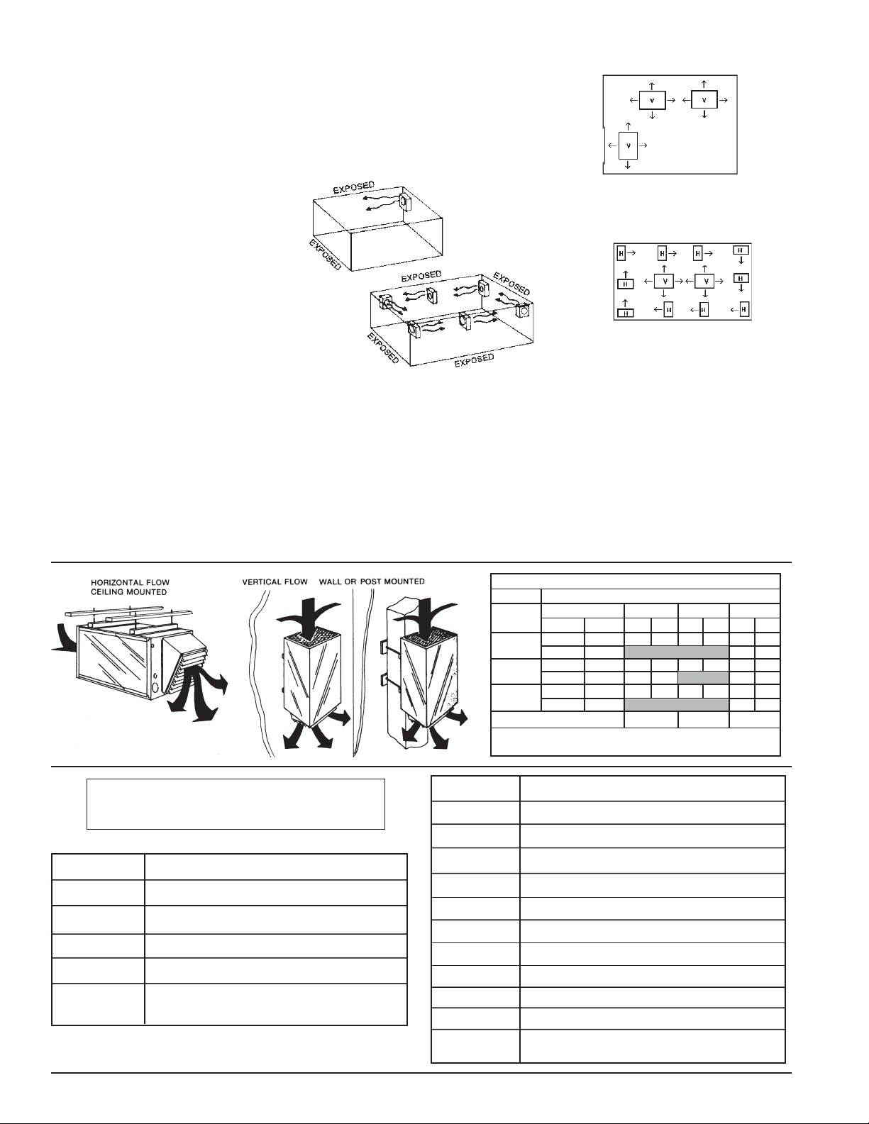
Mounting
KFUH heaters can be mounted vertically or
horizontally as shown. 3/8" weldnuts are welded into brackets and will accept 3/8 threaded
rod. A minimum of 6 inches clearance to
vertical and horizontal surfaces and 6 feet
minimum above floor are required. Louvers
can be adjusted for desired airflow.
Application Tips
First, calculate the heating loads in the conventional way using the N.E.M.A. handbook or
ASHRAE guide. Next, determine quantity and
size of heaters to be used. In instances where
large groups of people are normally settled
in the same location, use a large number of
smaller kW unit heaters. (Example: people on
a production line or skilled machine operations.) By utilizing heaters in this manner one
can best distribute uniform heat, prevent hot
drafts, reduce potential noise levels and balance the electrical operating demand.
When considering warehouse areas or
storage rooms (where heat distribution and
constant temperatures are less important) use
fewer heaters of higher capacity.
To maintain uniform heat and reduce stratified air it is recommended that the total CFM
of the units turn the air over approximately 3
times per hour.
Horizontal Mount
Smaller rooms can be heated by one unit
heater. Where two walls are exposed heaters
should be mounted as shown.
In larger rooms, units should be located so
their air streams wipe exposed walls without
Ceilings under 12 feet
6" Minimum
Clearance
Adustable
Louvers
blowing at them. Units should be located so
that the air stream of one supports that of
another thus setting up a circulatory air movement. (Distance between units to be approximately 1½ times published air throw).
Units should not be mounted horizontally in
areas having ceiling heights in excess of 10
to 12 feet.
Vertical Mount
Units should be mounted vertically where
they may otherwise interfere with assorted
material, handling equipment and in high bay
areas. Heaters should be situated to provide
free air circulation. Size and selection of units
should be based on recommended mounting
height.
Unit heaters are frequently used to combat
cold air inrush when loading dock doors are
opened. For such applications, one or more
units should be arranged to blow warm air
vertically in front of opening.
Ceilings over 12 feet
Motor HP
Dual Mounting
Where square footage is large and comfort
essential, both horizontal and vertical installations may best serve your requirements.
Mounting Limitations
KFUH unit heaters should not be used in
potentially explosive atmospheres. The finish
is not intended for direct salt spray exposure
in marine applications or the highly corrosive
atmospheres of swimming pools, chemical
storage bins, etc. Please refer to the factory
for explosion proof or marine application
heater information.
Do not install unit heaters above recommended maximum mounting height. Obstructions must not block unit heater air inlet or
discharge. To prevent possible injury heaters
must be mounted at least 6 feet above the floor
to prevent accidental contact with the heating
element or fan blade.
AIR DELIVERY CHART @ .2 static
MOTOR SPEED
Motor Load
230
230
230
Amps
3.4
1.7
3.2
1.7
3.8
1.9
Voltage
1/5
380/460
1/3
380/460
1/2
380/460
Wire Color
Air Volume = Cubic Feet per Minute (CFM)
Air Velocity = Feet per Minute (FPM)
Low Med
CFM FPM
775 570 860 630
1100 810 1250 920
1100 810
1250 920 1540 1130
Red
CFM
Blue
FPM
CFM
1000
1000
1540
1540
1750
1750
High
FPM
735
735
1130
1130
1285
1285
Black
The following accessories and/or options
may have been ordered with your unit.
Model
1E30-910
KFUH-90D
KFUH-RD
KFUH-90RD
KFUH-PTBL
2
Description
24V Wall Thermostat, range 50°- 90°
90 Degree Elbow w/ adjustable louver diffuser
Radial Diffuser
90 Degree Elbow w/ radial diffuser
Kit includes casters and mounting bracket to
create a Portable KFUH (no power cord)
Add Suffi x
-T
-2TS
-SF
-BR
-2S1
-2S3
-DS40
-DS60
-DS80
-DS100
-ND
Description
1-Pole thermostat - factory installed
2-Stage thermostat - factory installed
Summer fan switch - factory installed
Blower relay for remote fan only operation
2-Stage control, 1-Phase models
2-Stage control, 3-Phase models
40 Amp 3-Pole non-fused disconnect switch
60 Amp 3-Pole non-fused disconnect switch
80 Amp 3-Pole non-fused disconnect switch
100 Amp 3-Pole non-fused disconnect switch
No diffuser - 1" duct collar provided on discharge
side for connection to 14" x 14" duct
2007 KFUH.indd : 3/08
Page 3

CONTROL WIRING
Connect thermostat to terminals R and W for heating, R and G for air only. This can be done with a single stage heatcool thermostat or a single stage heat-only thermostat and a separate fan-only switch to control the fan-relay (optional)
installed on furnaces. Some models of furnace have two stage operation (optional) and are provided with terminals W1
and W2. If a single stage thermostat is used it should be connected to terminals R and W1 and a jumper wire installed
form terminals W1 to W2 (see enclosed control circuit wiring diagram). Some models of furnace have the 24 VAC power
available between terminal C and R for use with external air conditioning relay option. Never short or cross these two
terminals! The transformer will fail.
OPERATION
When control thermostat is turned up to demand heat the blower and heating elements should be energized. Furnaces
with sequences installed will have up to 30 seconds delay in start-up. When turned to cool position heat-cool thermostats
should bring on the blower only for air only.
MAINTENANCE
"CAUTION" Disconnect power at the main service panel before inspecting or cleaning this heater.
Lock or Tag breaker to prevent accidental shock.
Because of its rugged design, superior engineering and quality craftsmanship the King KFUH Unit Heater requires
little maintenance. With minimum care your electric heater should last a lifetime. King recommends changing the air
intake filter at least twice a year and checking the motor and blower for excessive dust / lint accumulation to maintain
the efficiency of the heater. While King recommends the filter be changed twice a year, your environment may require
more frequent changes.
WARRANTY
The King KFUH unit heater is warrantied against defects in workmanship and materials for five years from date of
installation. Extended warranty applies to heating element only; all other components are covered for two years. This
warranty does not apply to damage from accident, misuse or alteration; nor where the connected voltage is more than
5% above the nameplate voltage; nor to equipment improperly installed, wired or maintained in violation of this instruction
sheet. All claims for warranty work must be accompanied by proof of the date of installation. The customer shall be
responsible for all costs incurred in the removal or reinstallation or products, including labor costs, and shipping costs
incurred to return products to King Manufacturing. King, will repair or replace, at our option, at no charge to you with
return freight paid by King. King shall not be liable for consequential damages arising with respect to the product, whether
based upon negligence, tort, strict liability or contract. No other written or oral warranty applies, nor any warranties by
Representatives, Dealers, Employees of King or any other person. King Manufacturing can be contacted in Seattle,
Washington U.S.A. by phone at (206) 762-0400, fax (206) 763-7738 or website www.king-electric.com.
TROUBLE
Unit will not start
Motor will not stop
Unit goes off on high limit
Vibration noise
Unit has a buzzing sound
when not in use
Unit continues to heat after
room is up to set temperature
- does not shut off
TROUBLESHOOTER
POSSIBLE CAUSE
• Thermostat wire is not connected
• Circuit breaker is off
• 24 Volt transformer burned out
• Wire connection off or there are
broken wires
• Reset button tripped
• Wrong voltage
• Defective sequencer or contactor
• Dirty air filter
• Defective sequencer
• Defective limit control
• Power failure
• Blower assembly loose • Secure blower and motor cage
• Low voltage transformer
defective or loose
• Defective sequencer
• Defective thermostat
• Thermostat wires to ground
• Motor wires to ground
• Thermostat accidentally shorted
& contacts are welded
REMEDY
• Repair
• Reset
• Replace
• Repair or replace
• Reset
• Check the power source
• Replace
• Replace
• Replace
• Replace
• Reset manual limit push
button 20-35 kW units
• Replace or tighten
• Replace
• Replace
• Repair
• Repair
• Replace
- Make sure all connections are tight
2007 KFUH.indd : 3/08
3
Page 4

ITEM PART NUMBER DESCRIPTION
1
2
3
4
4000-09-E07K999
5
4000-03-E07J999
21-2405-00
21-2405-07
21-2405-9
21-2405-2
21-2405-12
21-2405-1
21-2405-6
21-3413-00
21-3413-01
60T11-201936
QOU260
QOU360
EB-200
ED-2
ERB-201
ED-3
4000-04-E07K999
Heating Element 5 kW / 240V
Heating Element 5 kW / 208V
Heating Element 5 kW / 480V
Heating Element 5.75 kW / 240V
Heating Element 5.75 kW / 240V
Heating Element 4 kW / 240V
Heating Element 4 kW / 480V
Heating Element - 3 Ph 5 kW / 240V
Heating Element - 3 Ph 5 kW / 480V
Auto. Limit Control - 60T11
Circuit Breaker 60 Amp - 1 Ph Square D
Circuit Breaker 60 Amp - 1 Ph Square D
Input Terminal Block - 1 Ph, 2P, 240V
Input Terminal Block - 1 Ph, 2P, 480V
Input Terminal Block - 3 Ph, 3P, 240V
Input Terminal Block - 3 Ph, 3P, 480V
Low Volt Transformer 240 / 208
Low Volt Transformer 277 / 24
Low Volt Transformer 480 / 24
4
R8330
15SH22-30956
6
R8229A
R8246A
60T25-330976
7
8
9
10
10935H3
9100233Q999
ELD-5-034
CA4SP
5KSP39FGW057AS
5KSP39FGW244AS
5KCP39MGE250AS
11
5KSP39FGG136S
4M207G
5KCP39M6J185S
DAO-3GJ005
DAO-3GJ007.5
12
DAO-3GJ010
FURNACE BLOWER SMALL
FURNACE BLOWER LARGE
13
Sequencer (used prior to 1981)
Sequencer (used after 1981)
Relay 28 Amp
Relay 46 Amp
Manual Reset Limit
Manual Reset Button
Dual Speed Fan Relay
Low Voltage Terminal Block
Ground Lug
1/5 HP 240V Motor
1/5 HP 480V Motor
1/3 HP 240V Motor
1/3 HP 480V Motor
1/2 HP 240V Motor
1/2 HP 480V Motor
Capacitor 3MP 370V
Capacitor 7.5MF 370V
Capacitor 10MF 370V
Blower Small for 1/5 HP Motors
Blower Large for 1/3, 1/2 HP Motors
120-8T-DD-.50PP Blower X-Large for 1/2 HP Motors
14
Air Filter 1" x 16" x 20"
2007 KFUH.indd : 3/08
 Loading...