

Page 1
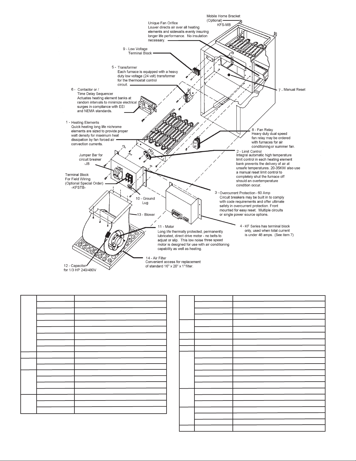
SAVE THESE INSTRUCTIONS
KF and KFS Series Electric Furnaces
Installation Instructions
“WARNING: RISK OF ELECTRIC SHOCK. CAN CAUSE
INJURY OR DEATH. DISCONNECT ALL REMOTE ELECTRIC POWER SUPPLIES BEFORE SERVICING.”
CAUTION: Turn off power source supplying the heater before attempting installation, maintenance or repairs. Lock or tag circuit
breaker or fuse panel door. Failure to do so could result in serious electrical shock, burns, or possible death.
It is extremely important to verify the electrical power supply is the same voltage as the heater being installed. 240 and 480 Volt heaters are
not interchangeable! Powering a 480 Volt unit with 240 Volt supply wires will reduce the heater output by approximately 75% resulting in no motor
power. Powering a 240 Volt unit with 480 Volt supply wires will destroy the heater and voids all warranties.
CHECK: Ensure blower wheel is free-turning and that element assemblies are in place. Be sure filter is in proper position and not torn or dam-
aged. Check that blower housing and motor have not separated from element compartment.
FIELD WIRING: King furnaces come equipped with 60 Amp circuit breakers installed for protection of the furnace internal wiring only. They also
serve as a disconnection means when required. A 240 Volt single phase circuit must be brought to each circuit breaker in the furnace as shown in the
wiring diagram. The terminals are identified as L1-L2, L3-L4, L5-L6 and L7-L8. The kW size of the furnace determines how many circuits are required.
The furnace power and electrical rating table indicates how many circuits each model furnace requires, the size of the branch circuit protection at the
distribution panel and the wire size required from distribution panel to the furnace. Consult your local and national electric codes for answers to any
questions. All wiring used must be approved for a minimum of 75°C. NOTE: No wire may have more than 120 VAC potential to ground. This must
be checked on installation to avoid motor damage. Unit must be grounded by connection of groundwire from the distribution panel to the terminal
provided in furnace. When the line voltage terminal block option is specified for single strike see wiring diagram for wire size and circuit protection
requriements.
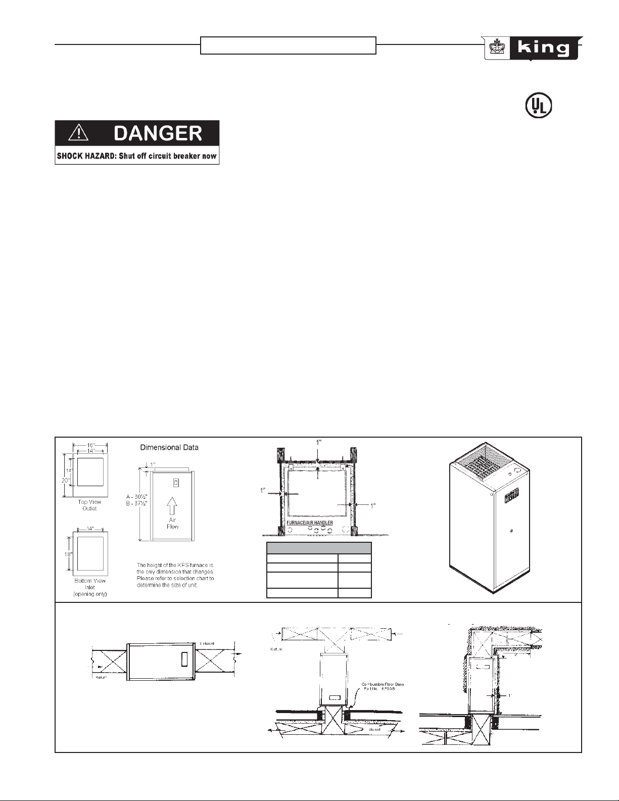
King furnaces can be installed with a minimum of 1 inch clearance for compact, space-saving installations in either vertical upflow, downflow or
horizontal position. When installed in the downflow position the combustible floor base accessory must be used.
NOTE: The attached Underwriters Labratories label pertains to the furnace only. It does not cover any air cooler, condensing unit or air cleaner,
which may be used with the furnace. The optional QOU cabinets are designed for slip-in addition of an evaporator coil at a later date. Approval of the
complete air conditioning system requires compliance with local codes.
DIMENSIONAL CLEARANCE
Cabinet sides
Cabinet front
Exhaust duct within
3 feet of furnace
Return air plenum
1 inch
0 inches
1 inch
0 inches
typical horizontal installation typical downflow installation typical upflow installation
King Electrical Mfg. Company • 9131 10th Avenue South Seattle WA 98108 • (206) 762-0400 fax (206) 763-7738
2007 KF-KFS.indd : 10/07
1
Page 2
ITEM PART NUMBER DESCRIPTION
Heating Element 5 kW / 240V
Heating Element 5 kW / 208V
Heating Element 5 kW / 480V
Heating Element 5.75 kW / 240V
Heating Element 5.75 kW / 240V
Heating Element 4 kW / 240V
Heating Element 4 kW / 480V
Heating Element - 3 Ph 5 kW / 240V
Heating Element - 3 Ph 5 kW / 480V
Auto. Limit Control - 60T11
Circuit Breaker 60 Amp - 1 Ph Square D
Circuit Breaker 60 Amp - 1 Ph Square D
Input Terminal Block - 1 Ph, 2P, 240V
Input Terminal Block - 1 Ph, 2P, 480V
Input Terminal Block - 3 Ph, 3P, 240V
Input Terminal Block - 3 Ph, 3P, 480V
Low Volt Transformer 240 / 208
Low Volt Transformer 277 / 24
Low Volt Transformer 480 / 24
1
2
3
4
4000-09-E07K999
5
4000-03-E07J999
21-2405-00
21-2405-07
21-2405-9
21-2405-2
21-2405-12
21-2405-1
21-2405-6
21-3413-00
21-3413-01
60T11-201936
QOU260
QOU360
EB-200
ED-2
ERB-201
ED-3
4000-04-E07K999
R8330
15SH22-30956
6
R8229A
R8246A
60T25-330976
7
8
9
10
10935H3
9100233Q999
ELD-5-034
CA4SP
5KSP39FGW057AS
5KSP39FGW244AS
5KCP39MGE250AS
11
5KSP39FGG136S
4M207G
5KCP39M6J185S
DAO-3GJ005
DAO-3GJ007.5
12
DAO-3GJ010
FURNACE BLOWER SMALL
FURNACE BLOWER LARGE
13
Sequencer (used prior to 1981)
Sequencer (used after 1981)
Relay 28 Amp
Relay 46 Amp
Manual Reset Limit
Manual Reset Button
Dual Speed Fan Relay
Low Voltage Terminal Block
Ground Lug
1/5 HP 240V Motor
1/5 HP 480V Motor
1/3 HP 240V Motor
1/3 HP 480V Motor
1/2 HP 240V Motor
1/2 HP 480V Motor
Capacitor 3MP 370V
Capacitor 7.5MF 370V
Capacitor 10MF 370V
Blower Small for 1/5 HP Motors
Blower Large for 1/3, 1/2 HP Motors
120-8T-DD-.50PP Blower X-Large for 1/2 HP Motors
14
Air Filter 1" x 16" x 20"
2
2007 KF-KFS.indd : 10/07
Page 3

CATALOG
#
KFS2003-1
KFS2404-1
KFS2005-1
KFS2405-1
KF4805-1
KFS2006-1
KFS2010-1
KFS2410-1
KF4810-1
KFS2412-1
KF4812-1
KFS2015-1
KFS2415-1
KF4815-1
KFS2418-1
KF4818-1
KFS2020A-1
KFS2420A-1
KF4820A-1
KFS2020-1
KFS2420-1
KFS4820-1
KFS2422-1
KF4822-1
KFS2025-1
KFS2425-1
KF4825-1
KFS2030-1
KFS2430-1
KF4830-1
KFS2435-1
KF4835-1
CATALOG
#
KFS2405-3
KF4805-3
KFS2009-3
KF2009-3
KFS2410-3
KF4810-3
KFS2012-3
KF2012-3
KFS2412-3
KF4812-3
KFS2015-3
KFS2415-3
KF4815-3
KFS2418-3
KF4818-3
KFS2420-3
KF4820-3
KFS2022-3
KFS2424-3
KF4824-3
KFS2030-3
KFS2430-3
KF4830-3
KFS2434-3
KF4834-3
* Includes motor load
PHASE
1
1
1
1
1
1
1
1
1
1
1
1
1
1
PHASE
3
3
3
3
3
3
3
3 20
3
3
3
3
KILO-
WATTS
3
4
5
6
10
11.5
15
17.25
20
20
22.5
25
30
34.5
KILO-
WATTS
5
9
10
11.25
12
15
17.25
22.5
24
30
34.5
BTU
(000)
10.2
13.6
17.1
20.5
34.1
39.2
51.2
58.8
68.3
68.3
76.8
85.3
102.4
117.7
BTU
(000)
17.1
30.7
34.1
38.4
40.9
51.2
58.8
68.3
76.8
81.6
102.4
117.7
VOLTS
208
240
208
240
480
208
208
240
480
240
480
208
240
480
240
480
208
240
480
208
240
480
240
480
208
240
480
208
240
480
240
480
VOLTS
240
480
208
240
480
208
240
480
208
240
480
240
480
240
480
208
240
480
208
240
480
240
480
AMPS*
17.8
20
27.2
24.2
12.1
32.2
51.4
45
22.5
51.3
25.7
75.5
65.9
32.9
75.2
37.6
99.5
86.7
43.4
99.4
86.5
43.4
96.9
48.6
123.4
107.4
53.8
147.4
128.2
65.7
146.9
73.6
AMPS*
15.4
7.7
28.3
27.4
13.7
34.6
32.3
16.1
43.5
45
21.4
44.8
22.4
51.3
25.7
65.6
60.9
30.5
86.5
75.3
37.3
86.2
43
CIRCUIT
PROTECTION
L1
L3L4L5
L2
20
20
40
30
15
40
60
60
30
70
40
60
40
60
30
50
60
40
50
60
60
60
60
60
60
60
60
60
60
60
60
60
30
60
60
30
20
60
60
60
60
60
60
30
15
60
60
40
CIRCUIT
PROTECTION
L1 / L2 / L3
100
110
100
110
75°
WIRE SIZE
L7
L1L2L3
L8
L6
#10
#10
#8
#10
#14
#8
#6
#6
#10
#8
#8
#8
#10
#6
#8
#6
#6
#6
#6
#6
#6
#6
#6
#6
60
60
60
60
60
20
10
40
40
40
40
60
50
30
60
40
70
30
75
50
50
60
#10
#10
#12
#6
#6
#10
#14
60
#8
L5
L6
L4
#10
#6
#6
#6
#6
#6
#6
#6
#6
#6
#6
#6
#6
#6
#6
#6
#6
#6
#6
#6
#6
#6
75°
WIRE SIZE
L1 / L2 / L3
#10
#8
#8
#8
#8
#6
#6
#10
#6
#8
#6
#12
#3
#4
#6
#2
#3
#6
#2
#6
# OF
ELEM.
L7
L8
#6
# OF
ELEM.
1
1
1
2
2
2
3
3
4
4
4
5
6
6
3
3
3
3
3
3
3
4
6
6
6
6
MOTOR
VOLTS HP
208
240
208
240
480
208
208
240
480
240
480
208
240
480
240
480
208
240
480
208
240
480
240
480
208
240
480
208
240
480
240
480
MOTOR
VOLTS HP
240
480
208
240
480
208
240
480
208
240
480
240
480
240
480
208
240
480
208
240
480
240
480
TEMPERATURE
LOW MED. HIGH
1/5
12°
1/5
16°
1/5
20°
1/5
24°
1/5
41°
47°
1/5
1/5
61°
70°
1/5
1/5
81°
1/3
57°
1/3
57°
1/3
72°
1/3
86°
1/3
99°
TEMPERATURE
LOW MED. HIGH
1/5
30°
1/5
37°
1/5
41°
46°
1/5
1/5
49°
1/5
61°
1/5
70°
1/3
57°
1/3
64°
1/3
69°
1/3
86°
99°
1/3
RISE
11° 9°
15°
18°
22°
37° 32°
42°
55° 47°
63° 55°
73°
51°
51°
63°
76° 62°
87°
RISE
25°
33°
37°
41°
44°
55°
63°
51°
56°
61°
76°
87°
62°
13°
16°
19°
36°
63°
41°
41°
51°
71°
20°
28°
32°
35°
38°
47°
55°
41°
46°
49°
71°
CABINET
SIZE
DIM. A
DIM. A
DIM. A
DIM. A
DIM. A
DIM. A
DIM. A
DIM. A
DIM. B
DIM. B
DIM. B
DIM. B
DIM. B
DIM. B
CABINET
SIZE
DIM. A
DIM. A
DIM. A
DIM. A
DIM. A
DIM. A
DIM. A
DIM. B
DIM. B
DIM. B
DIM. B
DIM. B
WT.
(lbs.)
57
57
57
57
65
65
74
74
76
76
76
81
85
85
WT.
(lbs.)
74
74
74
74
74
74
74
74
76
85
85
85
85
2007 KF-KFS.indd : 10/07
3
Page 4

C O N V E R S I O N O F T O R QU E T O H OR S E P O W E R
The power requirements for the Direct Drive curves in
this section are stated in torque units of ounce-inches
and ounce to feet.
HORSEPOWER FOR DIRECT DRIVE BLOWER WHEELS
The formula listed below may be used to convert
torque to horsepower.
TORQUE IN OZ-IN TORQE IN OZ-FT
HP=Torque (oz-in) x RPM HP=Torque (oz-ft) x RPM
1,008,400 84,033
AIR DELIVERY CHART
MOTOR SPEED
MOTOR
HP
VOLTAGE
1/5
1/3
1/2
380 / 460
380 / 460
380 / 460
MOTOR WIRE COLOR
MOTOR LOAD
AMPS
230
230
230
3.4
1.7
3.2
1.7
3.8
1.9
Air Volume = Cubic Feet Per Minute (CFM)
Air Velocity = Feet Per Minute (FPM)
LOW
CFM
775
1100
1250
RED
FPM FPM
570
810
920
MED
CFM CFM
630
860
1250
920
1130
1540
BLUE BLACK
HIGH
FPM
1000 735
1130
1540
1285
1750
RPM
1200
1100
1000
900
800
RPM
1200
1100
1000
900
800
0.04
0.03
0.03
0.03
0.02
600
0.71
0.66
0.59
0.54
0.48
TORQUE:
120
60
10
5
0.14
0.07
0.07
0.13
0.06
0.12
0.05
0.11
0.05
0.10
TORQUE:
720
840
60
0.86
0.79
0.71
0.64
0.57
70
1.00
0.92
0.83
0.75
0.67
50
(Upper value in Oz-In)
(Lower value in Oz-Ft)
180
240
15
20
0.21
0.29
0.20
0.26
0.18
0.24
0.21
0.16
0.19
0.14
(Upper value in Oz-In)
(Lower value in Oz-Ft)
960801080
90
1.14
1.29
1.05
1.31
0.95
1.19
1.07
0.86
0.95
0.76
300
0.36
0.33
0.30
0.27
0.24
1200
100
1.43
1.31
1.19
1.07
0.95
25
3603042035480
0.50 0.57
0.43
0.46
0.39
0.42
0.36
0.32
0.38
0.33
0.29
1320
1440
110
120
1.71 1.86
1.57
1.57
1.44
1.43
1.31
1.18
1.29
1.14
1.05
40
0.52
0.48
0.43
0.38
1560
130
1.70
1.55
1.39
1.24
CONTROL CIRCUIT WIRING DIAGRAMS:
SINGLE
HEAT
LOW VOLTAGE
FAN RELAY
Heat Anticipatory Setting:
Model KF or KFS 5 thru 18 = .4 amps
Model KFS 20 thr 35 = .8 amps
Low Voltage Thermostat
R
W
G
Y
Cooling Coil Relay
R
W
G
Furnace Low Voltage
Ter m in a l B lo c k
Thermostat Control Wiring diagram
for use with electric furnaces and
showing cooling coil relay hook-up
C
R
W
G
R
W
G
Fan Only Relays
YELLOW
RED
BROWN
FURNACE TERMINAL BLOCK
240VAC
Transformer
24VAC
Heat Relays
240VAC
240VAC
24 VAC
Element Relays
Fan only relay
L6
{
L5
L4
{
L3
L2
{
L1
60 Amp
Circuit Breaker
60 Amp
Circuit Breaker
60 Amp
Circuit Breaker
240VAC
Electronic Air Cleaner
Airflow Sensing Switch
Electronic Air Cleaner Wiring diagram
for use with electric furnaces and
utilizing an airflow interlock switch
To L im i t C on t ro l s
and
Heater Elements
4
2007 KF-KFS.indd : 3/08
Page 5

CONTROL WIRING: Connect thermostat to terminals R and W for heating, R and G for cool air only. This can be done
with a single stage heat-cool thermostat or a single stage heat-only thermostat and a separate fan-only switch to control
the optional fan-relay installed on furnaces. Some models of furnace have optional two stage operation and are provided
with terminals W1 and W2. If a single stage thermostat is used it should be connected to terminals R and W1 and a jumper
wire installed from terminals W1 to W2 (see enclosed control circuit wiring diagram). Some models of furnace have the
24 VAC power available between terminal C and R for use with the external air conditioning blower relay option.
OPERATION: When the control thermostat is turned up to demand heat the blower and heating elements should be
energized. Furnaces with sequences installed will have up to 30 seconds delay in start-up. When turned to cool position
heat-cool thermostats should bring on the blower only for cooling air.
MAINTENANCE
"CAUTION" Disconnect power at the main service panel before inspecting or cleaning this heater.
Lock or tag breaker to prevent accidental shock.
Because of its rugged design, superior engineering and quality craftsmanship and manufacturing the King KF-KFS Furnace
requires little maintenance. With proper care your electric furnace should last a lifetime. To maintain the efficiency of
the heater King recommends changing the air intake filter at least twice a year and checking the motor and blower for
excessive dust / lint accumulation - your environment may require more frequent changes.
TROUBLESHOOTER
TROUBLE
Runs too often,
Blows cold air
POSSIBLE CAUSE
• Thermostat heat anticipator set too low
• CFM of motor set too high
• Motor overheating
REMEDY
• Replace with adjustable anticipated thermostat
• Lower CFM of motor
Red wire - low speed
Blue wire - medium speed
Black wire - high speed
• KFS5-18 should have 1/5 HP motor;
1/2 and 3/4 HP motors are optional
Unit short cycles before
thermostat calls for off
Unit will not start
Motor will not stop
Unit goes off on high limit
Vibration noise
Unit has a buzzing sound
when not in use
Unit continues to heat after
room is up to set temperature
- does not shut off
• Thermostat anticipator set too low
• Intermittent opening of thermostat
or its wires
• Heat element burned out
• Circuit breaker off
• Motor overheating
• Thermostat wire is not connected
• Circuit breaker is off
• 24 Volt transformer burned out
• Wire connection off or there are
broken wires
• Reset button tripped
• Wrong voltage
• Defective sequencer or contactor
• Dirty air filter / ducts
• Defective sequencer
• Defective limit control
• Power failure
• Blower assembly loose • Secure blower and motor cage
• Low voltage transformer
defective or loose
• Defective sequencer
• Defective thermostat
• Thermostat wires to ground
• Motor wires to ground
• Thermostat accidentally shorted
& contacts are welded
• Adjust to .04 Amps for each sequencer
in furnace
• Repair or replace thermostat
• Replace
• Reset
• Motor overheating
• Repair
• Reset
• Replace
• Repair or replace
• Reset
• Check the power source
• Replace
• Replace
• Replace
• Replace
• Reset manual limit push
button 20-35 kW units
• Replace or tighten
• Replace
• Replace
• Repair
• Repair
• Replace
- Make sure all connections are tight
NOTE: When converting from oil, gas, etc. to electric, replace your old low voltage fixed-heat anticipator thermostat with one that has an adjustable heat anticipator.
2007 KF-KFS.indd : 10/07
5
Page 6

KING ELECTRIC FURNACE
1. Your King electric furnace has been designed to distribute heated air to your living quarters when connected to appropriate ducting.
2. On models KF5 & larger, the furnace operates under command of a low voltage wall thermostat.
3. Models KFS5 through KFS18 employ one sequencer relay, thus the thermostat heat anticipator should be set at 0.4.
4. Models KFS20 through KFS35 employ two thermal relays, thus the thermostat heat anticipator should be set at 0.8.
SEQUENCE OF OPERATION
5. With the thermostat set at 70°F and a temperature drop to about 69°F, the thermostat’s internal switch closes its contacts. About 30
seconds later the first heating element and the blower turn ”ON”. After another 30 seconds the second heating element is turned “ON”
continuing in 30 second intervals until all the heating elements in the furnace are “ON”.
6. When the thermostat is satisfied the “ON” process is reversed with the last element & blower turning “OFF” simultaneously.
7. Because of the many variables affecting heat loss (cold wall, sun rays, drafts, etc.) you may be more comfortable with the thermostat set
higher or lower than 70°F. It will take some experience to find a comfortable setting.
8. Your King electric furnace may be equipped with a cooling coil to accomplish summer cooling. It may also be equipped with an electronic air
cleaner to reduce dust, pollen and other household respiratory irritants.
9. If the furnace does not have an electronic air cleaner the filter will need to be replaced several times during the year or whenever it becomes
clogged. King recommends changing the filter at least twice yearly.
10. The furnace cannot deliver warm air when:
(a) all electric circuit breakers are turned “OFF”.
(b) the furnace filters are clogged with dirt and dust. Air is the vehicle for heat transfer. In order to deliver warm air an equal amount of
cold air must be drawn back to the furnace.
(c) the thermostat heat anticipator is set wrong - see paragraph three and four above.
(d) the furnace cold air return registers are blocked with furniture, throw rugs, etc.
(e) the furnace warm air registers are blocked with furniture, throw rugs, etc.
11. If the furnace is equipped with a cooling coil the “Outdoor Condensing Unit” must be turned “ON” when summer cooling is required and the
thermostat must be switched to the “Cooling” position with the temperature set around 76°F. Adjust temperature as necessary to find your
individual comfort level.
(a) On furnaces with cooling provisions the heat-cool thermostat has a HEAT/OFF & COOL position. The fan section has an AUTOMATIC
and ON position.
(b) For heating the system switch must be moved to HEAT position and the fan section should be set to AUTOMATIC.
(c) For cooling set the system to COOL and the fan section to ON. The fan will run constantly with the outdoor condensing unit running only
when your thermostat calls for cooling.
(e) If the fan needs to run continuously in either HEAT or COOLING set fan system to ON.
(f) The OFF position shuts down both heat and cooling and also shuts off the fan.
(g) In winter do not leave home with the furnace turned OFF. Instead set the thermostat to about 40°F with the furnace system in the HEAT
position. Doing this reduces the possibility of the indoor plumbing freezing.
12. If the furnace is equipped with an electronic air cleaner it must be cleaned several times during the year. You will want to study the HOME
OWNER’S MANUAL supplied with the electronic air cleaner.
MANUFACTURED HOUSING
DOWNFLOW INSTALLATION
1. Select a suitable, centralized location of the furnace (a closet, alcove or utility room).
2. The site selection must have adequate return air capability and must be located directly above existing or the planned location of the charge
plenum.
3. Cut a 15" x 15" opening in the floor exposing discharge plenum (or its intended location).
4. Place the base for combustible floor application into the floor opening. Secure it to the floor with screws (at least one on each side).
5. Put the duct connector into the base opening and mark plenum for cutting where the duct connector rests on it.
6. Remove the duct connector and cut to the outside of marking on plenum. Remove cut metal.
7. Replace duct connector back down through floor base. Bend alternate pre-cut tabs of duct connector 90° outward. Press duct connector into
plenum and bend remaining tabs into the plenum so it is firmly attached.
8. If necessary cut the top of duct connector so it is below the top of floor base, approximately 1".
9. Make the air duct tight by applying 2" duct tape to the tabbed-in portion of duct connector at the plenum opening and around the top of duct
connected inside the floor base.
10. Attach the duct connector to floor base using four (4) #8 hex head 1/2" self tapping screws.
11. Remove air filter from furnace. Set the furnace onto the combustible floor base with the filter end of the furnace facing upward. Replace filter in
furnace.
12. Make sure power is off on electrical circuits.
13. Remove door of furnace and bring proper electrical wiring into an appropriate opening provided and connect wiring per instructions on wiring
diagram.
NOTE: If needed, make sure any
return air grille has a free air area
of not less than 196 square inches
King Electrical Mfg. Company • 9131 10th Avenue South Seattle WA 98108 • (206) 762-0400 fax (206) 763-7738
6
2007 KF-KFS.indd : 10/07
 Loading...