

Page 1
electrical mfg. company
9131 - 10th Avenue South Seattle Washington 98108
INSTALLATION & MAINTENANCE MANUAL
SAVE THESE INSTRUCTIONS
for KCC & KCF SERIES CABINET HEATERS
WARNING
THIS UNIT IS MANUFACTURED TO OPERATE ON A SPECIFIC CONTROL VOLTAGE IN COMPLIANCE WITH YOUR
ORDER. STANDARD CONTROL VOLTAGES ARE 208 / 240 / 277 FOR 208 / 240 / 277 VOLT HEATERS.
24 VOLT CONTROL IS STANDARD ON 480 VOLT HEATERS. 208 / 240 OR 277 VOLT HEATERS MAY ALSO
BE ORDERED WITH AN OPTIONAL 24 VOLT CONTROL. IT IS IMPORTANT THAT YOU VERIFY YOUR POWER
SUPPLY VOLTAGE WITH THE HEATER THAT YOU HAVE CHOSEN. IMPROPER INSTALLATION OR FAILURE TO
FOLLOW THE PROCEDURES AS OUTLINED IN THIS MANUAL CAN RESULT IN SERIOUS ELECTRICAL SHOCK.
D
ISCONNECT ALL POWER FROM THE HEATER AT
INSTALL OR SERVICE THIS UNIT. ALL ELECTRICAL WIRING MUST CONFORM TO LOCAL ELECTRICAL CODES. HEATER
CIRCUIT MUST BE PROTECTED WITH THE PROPER SIZE FUSES OR CIRCUIT BREAKERS.
THE MAIN SERVICE PANEL AND LOCK BEFORE ATTEMPTING TO
Congratulations on the purchase of your new KING ELECTRICAL CABINET WALL
HEATER. Your new heater has been designed and built to withstand heavyduty commercial
and institutional usage. KCF models feature a whisper-quiet squirrel cage blower, with
permanently lubricated bearings. Both models feature long-life heating elements with aluminum plate fins for rapid heat transfer. A variety of factory installed options allow this heater
to be tailored to your specific application.
KCC-KCF.indd : 4/08
Page 2
Installation Instructions
WARNING
Before proceeding further with the installation of this heater, turn off the power and
lock to the supply line for the heater at the
main service box.
Remove the heater from the box and check for any
damage. Verify that the factory installed options are
correct for the application. Remove and set aside the
grill.
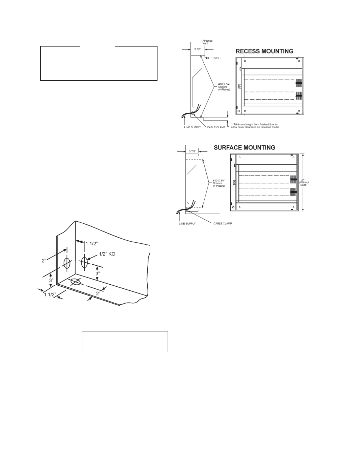
Select power supply wire type and size to comply
with local and national electric codes using heater
rating given in table. Connect wire to heater as
shown in wiring diagram attached to cover. Remove
one of the knockouts from back of unit. Secure
power supply cable with clamps (or run in conduit,
if required by local codes). Also run the wiring for a
remote thermostat, if required. Connect grounding
conductor to the green screw.
Fasten the heater to the wall with #10 screws, as
shown in the mounting diagrams. On recess models,
be sure to leave enough clearance to install the grill.
Replace the grill. Test the heater for proper operation.
JUNCTION BOX
(Left side wiring only)
Maintenance
With proper care your electric heater should last a
lifetime, however seasonal cleaning is recommended
to maintain the efficiency of the heater.
To clean the heater remove the four screws that hold
the grill in place and remove the grill. Remove dust or
lint from the heating elements and the fan blades with a
soft brush, compressed air, or a vacuum cleaner. KCF
units require a few drops of SAE 20 synthetic oil on the
motor shaft. Replace the grill and tighten the screws.
WARNING - All Power must be shut
off at the main service panel before
inspecting or cleaning the heater.
Warranty
All products covered by this instruction sheet are warranted against defects in workmanship and materials for
one year from date of installation, except heating elements which are warranted against defects in workmanship and materials for five years from date of installation.
This warranty does not apply to damage from accident,
misuse, or alteration; nor where the connected voltage
is more than 5% above the nameplate voltage; nor to
equipment improperly installed, wired or maintained
in violation of this instruction sheet. All claims for warranty work must be accompanied by proof of the date
of installation. The customer shall be responsible for all
cost incurred in the removal or reinstallation or products,
including labor costs, and shipping costs incurred to
return products to King Manufacturing. King Mfg. will
repair or replace, at our option, at no charge to you with
return freight paid by King. King Electrical Mfg. shall
not be liable for consequential damages arising with
respect to the product, whether based upon negligence,
tort, strict liability or contract. King Manufacturing can
be contacted in Seattle, Washington by phone at (206)
762-0400, by fax at (206) 763-7738 or by email at www.
king-electric.com
KCC-KCF.indd : 4/08
Page 3

KCC SELECTION CHART
(convection cabinet heater)
CATALOG # PHASE WATTS
KCC2-2020KCC2-2420KCC2-2720-
KCC2-4820-*
KCC3-2030KCC3-2430KCC3-2730-
KCC3-4830-*
KCC4-2040KCC4-2440KCC4-2740-
KCC4-4840-*
KCC4-2050KCC4-2450KCC4-2750-
KCC4-4850-*
* All 480V models require neutral wire for 277V fan motor
Add
Suffi x
1
for
Single
Phase
or
3
for
Three
Phase
BTUH
(000)
2000 6.8
3000 10.2
4000 13.6
5000 17
KCF SELECTION CHART
(fan-forced cabinet heater)
CATALOG # PHASE WATTS
KCF2-2020KCF2-2420KCF2-2720KCF2-4820-*
KCF3-2030KCF3-2430KCF3-2730KCF3-4830-*
KCF4-2040KCF4-2440KCF4-2740KCF4-4840-*
KCF4-2050KCF4-2450KCF4-2750KCF4-4850-*
* All 480V models require neutral wire for 277V fan motor
Add
Suffi x
1
for
Single
Phase
or
3
for
Three
Phase
BTUH
(000)
2000 6.8
3000 10.2
4000 13.6
5000 17
VOLTS
208
240
277
480
208
240
277
480
208
240
277
480
208
240
277
480
VOLTS
208
240
277
480
208
240
277
480
208
240
277
480
208
240
277
480
AMPS
1-PH 3-PH
5.6
9.6
4.8
8.3
N/A
7.2
2.4
4.2
8.3
14.4
7.2
12.5
N/A
10.3
3.6
6.5
11.1
19.2
9.6
16.7
N/A
14.4
4.8
8.3
13.9
24
12
20.8
N/A
18
10.4
AMPS
1-PH 3-PH
5.6
9.6
4.8
8.3
N/A
7.2
2.4
4.2
8.3
14.4
7.2
12.5
N/A
10.3
3.6
6.5
11.1
19.2
9.6
16.7
N/A
14.4
4.8
8.3
13.9
24
12
20.8
N/A
18
10.4
CABINET
SIZE
6
CABINET
6
WT.
(lbs.)
24" 30
36" 40
48" 50
48" 50
WT.
SIZE
(lbs.)
24" 35 1 34 95
36" 45 2 68 190
48" 55 3 102 285
48" 55 4 102 285
# OF
FANS
FAN
WATTS
CFM
FACTORY INSTALLED OPTIONS
ADD
SUFFIX
-1 1-Phase (fi rst extension after base model number)
-3 3-Phase (First extension after base model number)
-R Recessed Mounting
-S Surface Mounting
-SB Sub fl oor base, 3" high
-T 1-Pole Built-In Thermostat (40°F - 90°F)
-T2 2-Pole Built-In Thermostat (40°F - 90°F)
-RT
-CX
-RT24
-3PS 3-Position Switch (Heat / Fan / Off)
-DS1 2-Pole Disconnect Switch for 1-Phase Models
-DS3 3-Pole Disconnect Switch for 3-Phase Models
Power Contactor for 208, 240 & 277V models
Power Contactor and Transformer for 24V control
(for wiring to a remote low voltage thermostat)
DESCRIPTION
Line Voltage Terminal Block
(for wiring to a remote thermostat)
line voltage holding coil
Standard on 480V models
KCC-KCF.indd : 4/08
Page 4

L1
OPTIONAL
DISCONNECT
SWITCH
REMOTE WALL THERMOSTAT
OR OPTIONAL IN-BUILT
THERMOSTAT
HIGH LIMIT
L2
GND
L1
L2
L3
GND
TYPICAL 1-PHASE WIRING
208/240/277 VOLT
LINE VOLTAGE CONTROL
REMOTE WALL THERMOSTAT
OR OPTIONAL IN-BUILT
THERMOSTAT
OPTIONAL
DISCONNECT
SWITCH
CONTACTOR
HIGH LIMIT
ELEMENT
ELEMENT
ELEMENT
FAN(S)
ELEMENT
1,2 or 3 FANS
KCF UNITS
ONLY
ELEMENT
ELEMENT
TYPICAL 3-PHASE WIRING
208/240 VOLT
LINE VOLTAGE CONTROL
GND
CONTROL
TRANSFORMER
OPTIONAL
DISCONNECT
SWITCH
L1
L2
L3
NEUTRAL
(required on KCF
models only)
TYPICAL 480V 3-PHASE WIRING
24 VOLT CONTROL
24V
480V
REMOTE WALL THERMOSTAT
OR OPTIONAL IN-BUILT
THERMOSTAT
CONTACTOR
FAN(S)
1,2 or 3 FANS,
277 VOLT 1-PHASE
KCF UNITS ONLY
HIGH LIMIT
FAN(S)
ELEMENT
1,2 or 3 FANS
KCF UNITS
ONLY
ELEMENT
ELEMENT
KCC-KCF.indd : 4/08
 Loading...