

Page 1
electrical mfg. company
9131 - 10th Avenue South Seattle Washington 98108
INSTALLATION & MAINTENANCE MANUAL
SAVE THESE INSTRUCTIONS
for KB SERIES UNIT HEATERS
WARNING
THIS UNIT IS MANUFACTURED TO OPERATE ON A SPECIFIC CONTROL VOLTAGE IN COMPLIANCE WITH YOUR
ORDER. STANDARD CONTROL VOLTAGES ARE 208/240/277 FOR 208/240/277 VOLT HEATERS. 24 VOLT
CONTROL IS STANDARD ON 4 80 VOLT HEATERS. 120 VOLT CONTACTOR COILS ARE AVAI LABL E FOR EXTERNAL
120 VOLT CONTROL SUPPLY. 208/240 OR 277 VOLT HEATERS MAY ALSO BE ORDERED WITH 24 VOLT
CONTROL - KBLV-1 (WHICH INCLUDES TRANSFORMER AND CONTACTOR) OR KBLV-2 (WHICH INCLUDES
TRANSFORMER AND WIRING FOR HEATERS THAT ALREADY HAVE CONTACTORS AS STANDARD EQUIPMENT). IT
IS IMPORTANT THAT YOU VERIFY YOUR POWER SUPPLY VOLTAGE WITH THE HEATER THAT YOU HAVE CHOSEN.
IMPROPER INSTALLATION OR FAILURE TO FOLLOW THE PROCEDURES AS OUTLINED IN THIS MANUAL CAN RESULT
IN SERIOUS ELECTRICAL SHOCK OR DEATH. DISCONNECT ALL POWER FROM THE HEATER AT THE MAIN SERVICE
PANEL BEFORE ATTEMPTING TO INSTALL OR SERVICE THIS UNIT. ALL ELECTRICAL WIRING MUST CONFORM TO
LOCAL ELECTRICAL CODES. HEATER CIRCUIT MUST BE PROTECTED WITH PROPER FUSES.
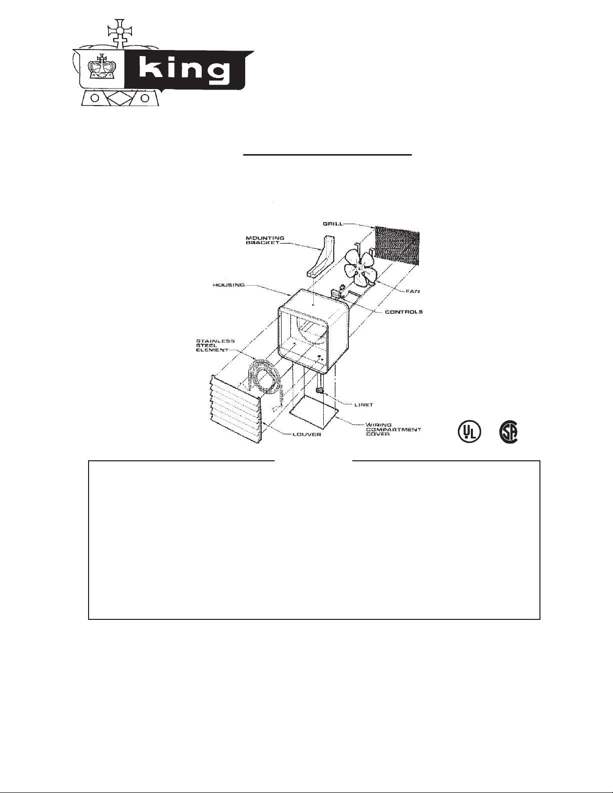
Congratulations on the purchase of your new KING ELECTRICAL UNIT HEATER. Your
new heater is made with the highest standards in electrical design and quality components
to ensure your satisfaction in durability and performance. The steel fin tube element which
has a 5 year warranty is backed by a heavyduty fan directing a strong flow of warm air to any
desired area through adjustable louvers. The rugged, totally enclosed, service-free motor
is combined with our fan design to maintain the correct relationship of air volume to final air
temperature. The quick access panel allows easy connections in the wiring compartment.
The universal bracket will allow ceiling or wall installation to fit your particular application.
KB.indd : 10/08
Page 2
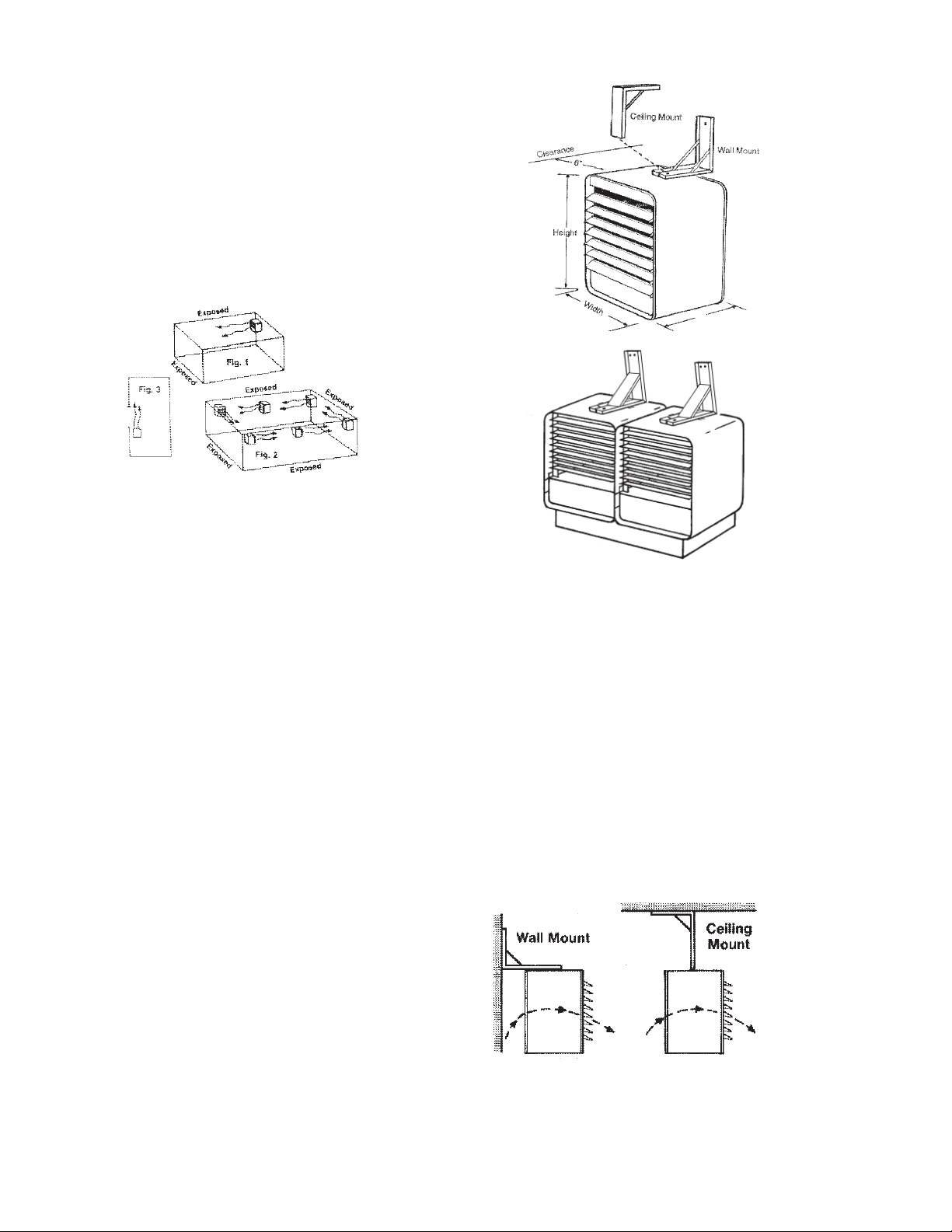
Location of Heater
The heater should be installed out of the reach of
persons. The direction of air flow should not be
restricted by machinery, beams, etc., and the air
flow should wipe exposed walls rather than blowing
directly at them. When more than one heater is used
in an area the heaters should be arranged so that
the air discharge of each heater supports the air flow
of the others to provide best circulation of warm air.
(see air flow chart)
Unpack & Inspect Your New Heater
Remove heater from the box and inspect it for any
damage. Verify you have received the mounting
bracket or thermostat if needed. (optional)
Mounting Height
Tools Needed
You will need the following tools to install your unit
heater:
• Screwdriver - (Phillips head & slotted)
• Pliers
• Electric Drill
• Wire Cutters
• Adjustable Wrench
Hardware Needed
You will also need the following hardware, which
can be purchased from your local hardware store or
electrical supply house:
• adequate gauge and length of wire for your applica tion
• proper size fuses or breakers to handle amperage
• proper wire connectors for your application
• fasteners appropriate for application that are strong
enough to hold unit
For certain applications conduit may be required.
Check local electrical codes. Also, if you run the wiring in conduit and wish to be able to turn the heater,
be sure to purchase enough flexible conduit to allow
the heater to be turned.
When the airflow of the heater is directed vertically or
horizontally the minimum mounting height is 6 feet.
Mounting heights depend upon building utilization and
heater kW capacity.
Distance From Walls
Be sure to maintain 6" minimum clearance to walls
and ceilings.
Mounting Bracket & Heater
Locate a stud in ceiling or wall and securely fasten
bracket to supporting surface with 3 1-1/4" screws.
Attach heater to bracket with 3/8" x 1" bolt & lock washer
supplied with bracket. After desired air discharge position has been determined, tighten bolt so the heater
will not pivot.
KB.indd : 10/08
Page 3

Wiring
WARNING
Before proceeding further with the installation of this heater, turn off the power and
lock to the supply line for the heater at the
main service box.
Remove wiring compartment cover. Remove one of
the knockouts from back of unit.
Select power supply wire to comply with local and
national electric codes using heater rating given in
table. Connect wire to heater as shown in wiring diagram attached to cover. Secure power supply cable
with clamps.
Connect grounding conductor to green screw. Reinstall wiring compartment cover.
Adjust the louvers to the desired position. NOTE: The
lovers are designed so they can not be completely
closed. Do not attempt to defeat this feature - damage to the unit can result.
capillary tube will exit knockout.
Adhere nameplate and attach thermostat with two
#6 screws as shown. Carefully bend capillary tube
through hole and attach bulb clamps with screws to
lip of chassis as shown in figure.
Connect wires as shown in wiring diagram. Reinstall
wiring compartment cover. Attach knob to thermostat.
Nameplate
6/32 Screws
Bulb Clamps
Knob
Capilary Tube
Thermostat Installation - Inbuilt
Remove wiring compartment cover. Remove plug
from back of chassis. Insert thermostat (model KBT
on standard units - for stainless steel see below) into
holes punched in chassis. Position thermostat so
Maintenance
Because of its rugged design, superior engineering and
high quality craftsmanship and manufacturing, the King
KB Unit Heater requires little maintenance. With proper
care your electric heater should last a lifetime, however,
seasonal cleaning is recommended to maintain the
efficiency of the heater.
To c le a n t he h ea ti n g el e me n t l oo s en t h e 4 Ph il l ip s h ea d
screws located behind the louvers in the corners of
the louver housing. Grasp the louver housing on both
sides, lift up and pull out. This provides access to the
heating element. Remove dust or lint with a soft brush
or a vacuum cleaner. Replace the louver housing and
tighten the Phillips head screws.
To clean the fan and motor remove the safety grill from
the rear of the heater. This provides access to the fan
and motor. Wipe the fan and motor with a soft cloth or
brush. The fan motor does not require lubrication.
WARNING - All Power must be shu t
off at the main service panel before
inspecting or cleaning the heater.
Stainless Steel Models require a special thermostat
model (TF115) that will be mounted to the outside
of the heater. This must be sealed properly and is
recommended to be done at the manufacturing plant.
For additional information please consult the factory.
Warranty
All products covered by this instruction sheet are warranted against defects in workmanship and materials for
one year from date of installation, except heating elements which are warranted against defects in workmanship and materials for five years from date of installation.
This warranty does not apply to damage from accident,
misuse, or alteration; nor where the connected voltage
is more than 5% above the nameplate voltage; nor to
equipment improperly installed or wired or maintained
in violation of this instruction sheet. All claims for warranty work must be accompanied by proof of the date
of installation. The customer shall be responsible for all
cost incurred in the removal or reinstallation or products,
including labor costs, and shipping costs incurred to
return products to King Manufacturing. King Mfg., will
repair or replace, at our option, at no charge to you with
return freight paid by King. King Electrical Mfg., shall
not be liable for consequential damages arising with
respect to the product, whether based upon negligence,
tort, strict liability or contract. King Manufacturing can
be contacted in Seattle Washington by phone at 206
762-0400 or by fax at 206-763-7738.
KB.indd : 10/08
 Loading...