

Page 1
TROUBLESHOOTING GUIDE
Digital HDTV Over-the-Air Antennas
11200 Hampshire Avenue South, Bloomington, MN 55438
PH 952.922.6889 || FAX 952.922.8424 || kingconnect.com
Page 2

Page 3

NOTE: Depending on the model, KING Jack antennas may or may not have a KING SureLock™ Signal Meter installed
in the interior enclosure. Variations to operation and troubleshooting because of this are called out where
necessary.
TABLE OF CONTENTS
Section Contents Page
1. INTRODUCTION ........................................................2
2. WARRANTY INFORMATION ...............................................3
3. KING JACK OPERATION WITH SURELOCK® SIGNAL METER ...................4
4. KING JACK OPERATION WITHOUT SURELOCK SIGNAL METER ................5
5. TROUBLESHOOTING FLOWCHART REFERENCE DIAGRAMS ................ 6-7
6. TROUBLESHOOTING FLOWCHART ...................................... 8-9
7. BLOCK TIMES .........................................................10
8. REPLACEMENT PARTS LIST .............................................11
9. REPLACE POWER INJECTOR ............................................12
10. REPLACE SIGNAL METER...............................................13
11. REPLACE ANTENNA HEAD ........................................... 14-15
12. REPLACE KING JACK ASSEMBLY...................................... 16-17
WARRANTY CONSIDERATION FORM......................................18
KING Jack, KING SureLock and Simply better, by design. are trademarks of Electronic Controlled Systems, Inc.
KING, JACK and SureLock are registered trademarks of Electronic Controlled Systems, Inc.
Page 1
Page 4

Section 1 INTRODUCTION
The KING Service Department is dedicated
to providing its dealers and customers
with the highest possible level of satisfaction and service.
The KING Service Department stays up to date with the latest information to assist you in keeping
troubleshooting and repair time to a minimum.
When calling our service department, a KING technician will issue a Customer ID Number (or Case
Number) and then clearly dene the proper course of action to follow. If any work is to be performed
or parts replaced, a Service Order Number will also be issued. Additionally, the KING technician will
create a call log to aid in properly documenting the warranty claim.
IMPORTANT!
For warranty reimbursement, you must call KING for a
Service Order Number
BEFORE performing any work: (952) 922-6889.
Page 2
Page 5

Section 2 WARRANTY INFORMATION
KING Jack Antennas are covered by a TWO YEAR PARTS AND ONE YEAR LABOR limited warranty from the date of
original purchase. This warranty does not cover installation and external wiring, or refurbished units. This warranty also
does not apply where:
• The product has been abused, misused, improperly installed or improperly maintained.
• Repairs have been made or attempted by others that are not certied by KING to do such repairs.
• Repairs are required because of normal wear and tear.
• Alterations have been made to the product.
• The antenna head, base mount or interior enclosure has been opened without authorization.
• Damage has been caused by power washing.
• Circumstances beyond the control of KING cause the product to no longer operate correctly.
• Customer is not the original owner.
PROCESSING A WARRANTY CLAIM
IMPORTANT! Only KING certied dealers are authorized to perform warranty evaluations and repairs.
1) Technician must rst determine if the unit is under warranty by verifying original owner and date of original
purchase. Dealer must provide one of the following when submitting a warranty claim:
• copy of original purchase receipt, or
• if unit was installed by an OEM, verication of in-service date
2) Technician must call KING to get a Service Order Number (952) 922-6889.
Technician must not proceed without a Service Order Number.
• A KING technician will issue a Service Order Number and advise technician on how to proceed.
3) After repairs are completed, the following must be sent to KING:
• Defective Part if requested by KING (Warranty Labor Claim will not be processed until part is returned.)
• Warranty Consideration Form
• Copy of Work Order
• Proof of Purchase
KEY POINTS
1) For units in service longer than one year, the customer is responsible for labor time.
2) Installation parts (for example coax cables) are not covered.
3) Replacement parts are sent directly from KING. DO NOT USE NEW PRODUCT FOR WARRANTY
REPLACEMENT WITHOUT WRITTEN AUTHORIZATION FROM KING.
4) Technician must call KING before performing any work for which warranty labor reimbursement will be submitted
to KING. A KING technician will issue a Service Order Number and specify the allotted time for the repair. If
repairs will take longer than the allotted time, and the servicing dealer wishes to receive proper reimbursement, the
technician must receive prior authorization to exceed the allotted time.
5) Warranty claims must include: proof of purchase, Warranty Consideration Form with Service Order Number, and
copy of work order with labor time which matches that allotted by KING.
6) KING shall reimburse the servicing dealer for warranty work at their published labor rates.
7) If returning defective part, include paperwork with part. Clearly mark the Service Order Number on outside of box.
Page 3
Page 6
Section 3 KING JACK OPERATION WITH SURELOCK SIGNAL METER
OPERATION
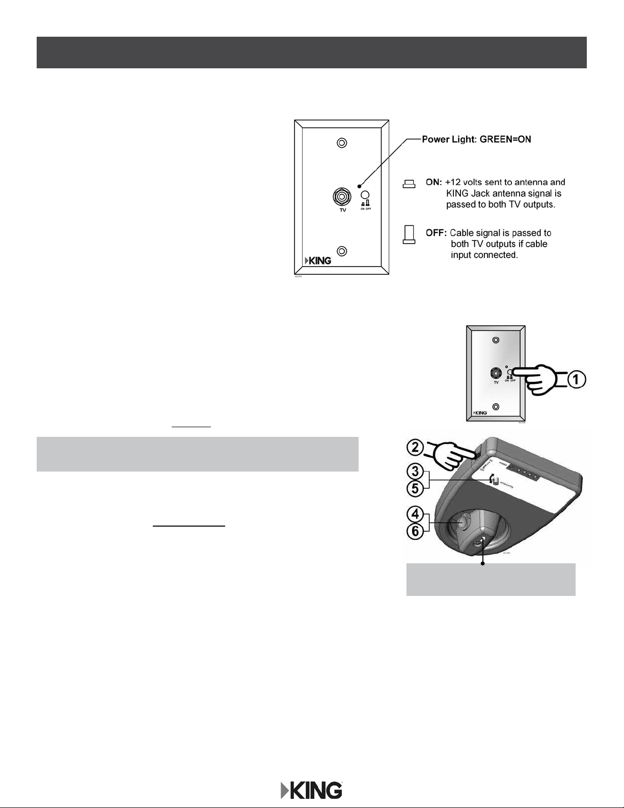
The wall mount Power Injector will switch between
cable feed and over-the-air signals from the
KING Jack antenna.
To use the Power Injector, simply turn the unit on with the
ON/OFF button. When on (button depressed), the power
light will turn green indicating +12 volts to the antenna,
and the over-the-air signal from the KING Jack antenna
will be fed to the two TV outputs.
When off, the cable TV signal will be fed to the two TV
outputs if wired for cable TV input.
POSITIONING THE ANTENNA
1. Turn on Power Injector (power is now supplied to the KING Jack antenna).
(Make sure TV is also on.)
2. Turn on KING SureLock Signal Meter with switch on side of rotational knob enclosure.
3. Rotate attenuator dial fully clockwise.
NOTE: In step 4, LED lights will illuminate from left (next to power) to right.
All LED lights may not illuminate depending on signal strength.
4. Depress button on rotational knob and rotate antenna
until maximum number of LED lights illuminate on signal meter.
5. Rotate attenuator dial counter clockwise until last illuminated LED light ickers.
6. Rotate antenna to illuminate last ickering LED light.
7. Repeat steps 5 and 6 to pinpoint signal reception.
8. Follow instructions for TV or converter box to scan for available channels.
NOTE: Arrow on knob indicates which
direction antenna is pointing.
Page 4
Page 7
Section 4 KING JACK OPERATION WITHOUT SURELOCK SIGNAL METER
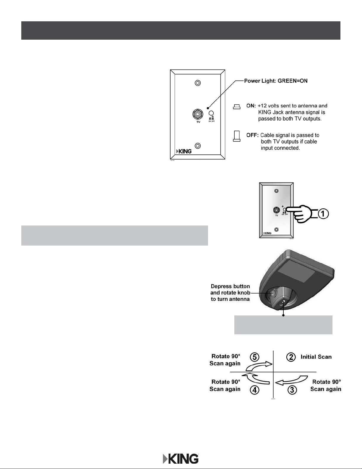
OPERATION
The wall mount Power Injector will switch between
cable feed and over-the-air signals from the
KING Jack antenna.
To use the Power Injector, simply turn the unit on with the
ON/OFF button. When on (button depressed), the power
light will turn green indicating +12 volts to the antenna,
and the over-the-air signal from the KING Jack antenna
will be fed to the two TV outputs.
When off, the cable TV signal will be fed to the two TV
outputs if wired for cable TV input.
POSITIONING THE ANTENNA
1. Turn on Power Injector (power is now supplied to the KING Jack antenna).
(Make sure TV is also on.)
NOTE: In steps 2-5, keep track of in which direction you received the most
channels when each scan is complete.
2. Perform an initial channel scan per the digital TV or digital TV
converter box manufacturer’s instructions.
3. Depress button on rotational knob and rotate antenna 90 degrees.
Scan again.
4. Depress button on rotational knob and rotate antenna 90 degrees.
Scan again.
5. Depress button on rotational knob and rotate antenna 90 degrees.
Scan again.
6. Reposition the KING Jack antenna to where you received the most
channels. Choose one of those channels on the TV.
7. Now monitor the signal strength screen and ne tune the
KING Jack until the highest signal strength is achieved.
8. Perform one nal scan.
NOTE: Arrow on knob indicates which
direction antenna is pointing.
Page 5
Page 8

Section 5 TROUBLESHOOTING FLOWCHART REFERENCE DIAGRAMS
Page 6
Page 9

Page 7
Page 10

Section 6 TROUBLESHOOTING FLOWCHART
Page 8
Page 11

Page 9
Page 12

Section 7 BLOCK TIMES
REPLACEMENT PROCEDURE TIME IN MINUTES
Power Injector 30
Signal Meter 30
Antenna Head 30
KING JACK Assembly 60
NOTE: See sections 9-12 for detailed instructions.
Page 10
Page 13

Section 8 REPLACEMENT PARTS LIST
21631
Ceiling enclosure with signal meter
20954 Antenna Head (White)
21053 Antenna Head (Black)
20263B Coax, splitter to antenna head (metered KING Jack)
10121-1 Coax, splitter to signal meter (metered KING Jack)
21038 Splitter (metered KING Jack)
21045 Coax w/F-connector, coach coax to antenna head (non-metered KING Jack)
NOTE: Power injector part numbers vary and are marked on back of power injector.
Page 11
Page 14

Section 9 REPLACE POWER INJECTOR
NOTE: Make sure power to power injector is turned off before proceeding.
Page 12
Page 15

Section 10 REPLACE SIGNAL METER
NOTE: Turn off power injector before proceeding.
Page 13
Page 16

Section 11 REPLACE ANTENNA HEAD
NOTE: Turn off power injector before proceeding.
Page 14
Page 17

Page 15
Page 18

Section 12 REPLACE KING JACK ASSEMBLY
NOTE: Turn off power injector before proceeding.
Page 16
Page 19

Page 17
Page 20

Page 18
Page 21

NOTES:
Page 19
Page 22

NOTES:
Page 20
Page 23

Page 24

Simply better, by design.
™
11200 Hampshire Avenue South, Bloomington, MN 55438
PH 952.922.6889 || FAX 952.922.8424 || kingconnect.com
© 2016 KING
22412 Rev A, KING Jack Antenna Troubleshooting Guide
 Loading...